May 18, 2007 - Lightning strike is a dangerous natural phenomenon that can cause ..... result of lightning strike distance does not always suit with the actual.
16 Lightning Location and Mapping System Using Time Difference of Arrival (TDoA) Technique Zulkurnain Abdul-Malek1, Aulia1,2, Nouruddeen Bashir1 and Novizon1,2 1Universiti
Teknologi Malaysia, Andalas, 1Malaysia 2Indonesia
2Universitas
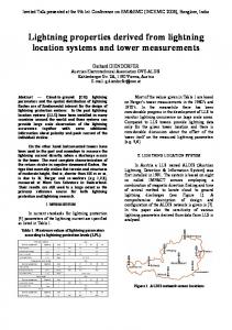
1. Introduction Lightning strike is a dangerous natural phenomenon that can cause various problems. Telecommunication subscriber lines (TSLs) and electrical power lines are two systems that are almost always affected by nearby lightning strikes. Voltages in the telecommunication subscriber line (TSL) do get induced by nearby lightning strikes. The induced voltage can be carefully measured and lightning parameters such as the lightning current wave shape, lightning peak current and strike locations be reproduced. Better designs of lightning protection systems can be realised if data on lightning strike distribution in a given region is known. Commercial lightning mapping or locating systems are based on several technologies (Araujo, 2001; Kenneth, 2003). The two most popular methods are those based on the Time of Arrival (ToA) and the Directional Finder (DF) principles. An example of the lightning locating system (LLS) based on the ToA method is the countrywide LLS owned by the Malaysian national power company (TNB). The system is capable of determining the coordinates of the cloud-to-ground lightning strikes within 500m accuracy. However, for a localised distribution of lightning, say within 1 square km area, this accuracy is too large for the data to be meaningful. In this work, a new method to determine the coordinate of any cloud-to-ground lightning strike within a certain localised region is presented. The system is suitable for determining lightning strike distributions for a small area by measuring the induced voltages due to lightning strikes in the vicinity of an existing overhead telephone lines (Aulia, 2008a; Aulia, 2008b; Sorwar, 1997; Tominaga, 2003). LabVIEW was employed to measure and acquire lightning parameters such as peak current, wave shape; strike location as well as map the location of the strikes. A mock telecommunication subscriber line system (MTSL) was designed in the field to capture the lightning induced voltages. The model for the MTSL was developed based on the concept shown in Figure 1. If a cloud to ground lightning strike occurs near an overhead telecommunication cable, and if the location of the strike is placed exactly in the middle of the telecommunication cable, then the induced voltage on the cable due to the strike will not only travel in opposite direction toward the cable ends, but also both waves will arrive at
344
Practical Applications and Solutions Using LabVIEW™ Software
the cable’s end at the same time. In other words, there is no difference in the time of arrival, or the time difference of arrival (TDoA) is equal to zero.
Cloud to Ground Lightining Flash
ng elli f t rav e le t th ed uc t t o ind rren e % 50 ve cu sid wa
ng ell i ht r av e rig t d h uce to t ind ren t e r % 50 e cu sid v wa
Overhead telecommunication cable
Telecommunicatio n Tower
Ground point
Fig. 1. Cloud to ground lightning strike model adopted for developing the localized lightning locating system (LLLS) using the existing overhead telecommunication cable
2. Lightning detection technique based on the time difference of arrival In this work, the mapping of the lightning strike locations was done based on the time difference of arrival (TDoA) of the travelling waves. Lightning induced voltage causes a transient on a cable. The point of induction could be treated as a transient source or a fault source. Figure 2 show the Bewley Lattice diagram depicting what happens to the induced voltages based on travelling wave theory (Piantini, 2007). Points A and B are the points of induction caused by lightning strike near the cable. For an induced voltage at point A, in the first half of the cable X < L/2 Figure 2a, the point of induction could be determined using the following formulas: td1 = 3T1 − T1 = 2T1 = 2( X / V )
td2 = T2 − T1 = (Y / V ) − ( X / V )
Lightning Location and Mapping System Using Time Difference of Arrival (TDoA) Technique
345
Fig. 2. (a) Bewley Lattice diagram for a fault at (a) first half section of the line at A (b) second half section of the line at B. By eliminating V, results in X = L*
(1 / 2 ) ( 1 + ( td2 / td1 ) )
m
(1)
where L = X + D the time for the wave to travel distance X T1 T2 the time for the wave to travel distance Y ( td1 ) transient time between the first and the second spikes at the first side (sending end); ( td2 )
transient time between the initial arrivals of the travelling wave at both sides of the
cable (sending and receiving ends); V travelling-wave velocity; L total length cable line in meters. For an induced at point B in the second half of the cable at (X > L/2), as shown in Figure 2b, the distance could be calculated using the following equation: ⎛ (1 / 2) X = L* ⎜1 − ⎜ 1 + ( td2 / td1 ) ⎝
(
)
⎞ ⎟m ⎟ ⎠
(2)
Both equations are independent of the velocity of propagation. This fact makes this technique very powerful compared with other traditional techniques.
3. Small scale model A small scale model was set-up to test and verify the LLS concept. The cloud–to-ground lightning flash was simulated by a purposely-made surge current generator. The generator consists of a high voltage DC generator, and an impulse waveshaping circuit as shown in Figure 3. A series resistor (5-10 Ω) was added in series to limit or control the lightning current.
346
Practical Applications and Solutions Using LabVIEW™ Software
The height of the copper strip was 2 m. A pair of RG 59 coaxial cable was laid horizontally to mimic the TSL in a certain distance, d, and height, h. The impulse current was measured using a Rogowski coil that has a sensitivity of 0.01 V/A. The induced voltage on the cable was measured through a 50 Ω resistor at the cable’s end. A Tektronix 3052 oscilloscope was with a 10m cable was used to measure the induced voltage, the time scale was set to nanosecond range. In this experiment, the end of the cables closer to the copper strip were left opened and the other end was terminated through resistor for measuring purpose. Coaxial cable High Surge current Generator
High Surge current Generator
copper strip
copper strip
d d
Coaxial cable
l h
(a)
Measuring resistance
(b)
Fig. 3. The circuit connection to simulate the lightning induced voltage on a coaxial cable for reduced scale model (a) top view and (a) side view, where d is the distance between copper strip and the coaxial cable and h is the height of cable laid down above the ground or floor.
4. Travelling wave speed The speed of the travelling wave in the cable was calculated based on the experimental result as follows:
v = l /t
(3)
where ν = velocity, l = distance travelled, and t = time travelled The velocity, ν refers to the induced voltage signal speed in telecommunication cable. In this work, the speed was calculated based on the measurement results. Figure 4 shows the set-up to determine the travelling wave velocity in the telecommunication and coaxial cables. The lengths of cable 1 and cable 2 were varied. Table 1 shows the tabulated results. Figure 5 shows the correlation between difference of distance (DoD) and time diference of arrival (TDoA) of twisted telephone line (in Figure 5a) and RG 59 coaxial cable (in Figure 5b). Based on the measurements, it can be concluded that an average TDoA of 4.6 ns and 5.1 ns represents 1 m propagation for the telecommunication cable and coaxial cables respectively.
347
Lightning Location and Mapping System Using Time Difference of Arrival (TDoA) Technique Oschilloscope
Function Generator
Cable 1
Cable 2
Fig. 4. The speed of travelling wave measurement in the cable to get the TDoA/m Do D (m) TDoA (ns) DToA per meter (ns/m) DToA in avarage (ns/m)
0 0
1 4.64
2 9.28
7 33.5
8 37.12
9 41.53
10 46.4
11 51.04
18 84.6
19 88.2
20 92
0
4.64
4.64
4.79
4.64
4.614
4.64
4.64
4.7
4.64 4.6
4.660 (a)
DoD (m) TDoA (ns) TDoA per meter (ns/m) TDoA in avarage (ns/m)
0 0
1 5.2
2 9
7 35.6
8 41.6
9 45.8
10 52.4
11 18 57.6 91.8
19 96.6
20 101
0
5.2
4.5
5.09
5.2
5.089 5.24 5.236 5.1
5.084
5.1
5.082 (b)
Table 1. Time difference of arrival (TDoA) and the travelling wave speed in (a) Telecommunication Subscriber Line (b) RG 59 coaxial cable.
(a)
(b)
Fig. 5. The correlation between difference of distance (DoD) and time diference of arrival (TDoA) of (a) twisted telephone line and (b) RG 59 coaxial cable
5. Impulse current generator Two types of impulse current generators were used in the research work. Firstly, a manually set up impulse generator described in (Aulia, 2008a and Aulia, 2008b) and secondly a
348
Practical Applications and Solutions Using LabVIEW™ Software
commercial impulse generator manufactured by Haefely. The former was used during working with the small scale system while the latter was used during the calibration process of MTSL. Pictorial view of the impulse generators are shown in Figure 6.
(a)
(b)
(c)
Fig. 6. (a) The manually set up impulse current generating unit, (b) the corresponding input voltage control unit, (c) Commercial impulse current generator
6. The measurement, transmission and central processing station Several types of voltage transducers installed at the line ends can be used to measure the induced voltage due to lightning strikes (Altafim, 1992). In this work, specially modified voltage transducers were used. Since the lightning strike coordinate was calculated based on the arrival time delays of various induced voltage impulses, any delay or interference in the transmission of the induced impulses can influence the calculation. Therefore, the transmissions of data from the voltage transducers to the central processing station (within P06 building) were implemented using optical fibres. Optical transmitters and receivers (transceivers) similar to the ones described by (William, 2006; Kurata, 2007) were used. Apart from the optical receivers, the central processing station consisted of a LabVIEWenabled four-channel high speed oscilloscope and a personal computer (PC). The block diagram of the measurement and data acquisition system for this work is shown in Figure 7 and the typical flowchart for the data acquisition implementation is as shown in Figure 8. LabVIEW 8.5 software was used for the control of the data acquisition system. All measuring equipment was physically checked to make sure they have been correctly connected and installed. Referring to Figure 8, when the system is switched on, it will initialize and be in standby mode waiting for a trigger. In the event of a trigger data will be acquired and then verified. If the correct signal has been captured, the system determines the lightning time of arrival, induced voltage, current and map the lightning location in the Cartesian. On the other hand if the signal captured was not correct the system will be in standby mode and waits for another event. The location will then be mapped in the Cartesian system. These parameters will then be stored and printed. If another lightning event is to be captured, the system returns back to standby mode else stops.
Lightning Location and Mapping System Using Time Difference of Arrival (TDoA) Technique Lightning Strike Nearby
Telecommunication Subscriber Line (TSL)
Electrical to Optical Transducer
Voltage Transducer
Optical data
Voltage Transducer
Electrical to Optical Transducer
Optical to Electrical Transducer
Optical data
PC and data collecting, processing and analyzing
DAQ and signal conditioning
Laser Bias
Fig. 7. The measurement and data acquisition system of the LLLS Start
Read Configuration file
Initialize Determine delay limit Wait for event trigger Acquire Data
Verify The Data
Determine The different time of arrival Determine Lightning Location
Yes Correct signal
yes
No
Continue
Yes Determine the induced voltage Calculate the Lightning Curernt Store data
Print or display
Fig. 8. Typical flow chart for lightning data acquisition system
No Stop
349
350
Practical Applications and Solutions Using LabVIEW™ Software
6.1 Measuring equipments In this work, the key measuring equipments used were digital storage oscilloscope, high current transducer and Picoscope. The oscilloscopes were used for the purpose of measuring the induced voltage both in the laboratory and field tests. A high current transducer with a 0.01 V/A sensitivity was used to measure the current generated from the impulse generator. 6.2 Data acquisition system All data was acquired, analysed and save in the data acquisition system which consisted of a Picoscope and LabVIEW program. Picoscope is a device that resembles the functions of an oscilloscope but runs on computer. Usually, Picoscope comes with software that turns it into a PC oscilloscope. In order to connect with LabVIEW, a virtual instrument (VI) interface was developed. LabVIEW Picoscope VI program links the Picoscope with LabVIEW software. To accommodate the need of very high speed data acquisition, the new version of Picoscope Technology, 5203 series having maximum data capturing speed of 200 MS/s was used. Data can be saved in temporary memory and erased each time capturing data restarted. Alternatively, the captureed data could be saved in the Excel readable files or using Picoscope accompanied software.
7. The mock telecommunication subscriber lines and cartesian model Lightning induced voltages on overhead lines could be studied using models (Piantini, 2007). Piantini studied the lightning induced voltages on overhead lines of power distribution systems using a scaled down model. However, this is prohibitively complex to be treated theoretically. The scale model was successfully implemented at the University of São Paulo, São Paulo, Brazil. A similar approach was adopted and implemented in this work. W
T17
S
Figure Title : Lay out of Mocking Telecommunication Subscriber Line Legend: Legend Telecommunication subscriber Line Tower Position Tower Number
O T1,...T19
N
Title
Cable arm
50 cm
Prepared For
Project VOT No. 79032
Date
May 18, 2007
T16
n raa e t u jur k e i K tri ult Elek k Fa
T15
IVAT Park Area T14
Room 241-01 Data Center
PO6 IVAT
T18
210 m
20 cm
Aulia
E
Prepared by
T13
40 m
T12
6m T11 Jalan Lengkok Kuasa
270 m
Concr ete T1
(a)
30 m
T2
T3
T4
T5
T6
T7
T8
T9
T9
T10
(b)
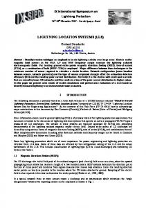
Fig. 9. (a) Aerial view of the mock TSLs location (Google Earth June 4, 2008) (b) Diagrammatic layout of the mock TSLs The MTSL was installed in a chosen area at the Institute of High Voltage and High Current (IVAT). Figure 9 a shows details of the site (Google Earth dated June 4, 2008) and Figure 9 b shows the schematic diagram of the mock TSLs. The coordinates of various spots are given as follows: P15: latitude 1°33'30.51"N and the longitude 103°38'36.31"E; P16 (crossroad):
Lightning Location and Mapping System Using Time Difference of Arrival (TDoA) Technique
351
latitude 1°33'37.72"N and longitude 103°38'38.90"E; and Marine Building: latitude 1°33'39.72"N and longitude 103°38'32.60"E. Two types of cables were laid down on the top of the seventeen installed telecommunication towers having heights of 6 m from the ground. Ten towers (T1-T10) with a total cable length of 270 m were installed alongside P15 to P16 buildings. This line route was designated as Line I. Perpendicular to this, the rest of the seven towers (T11-T17) with a total cable length of 210 m were laid alongside P06 to Marine buildings. This line route was designated as Line II. The cable types were twisted telephone and coaxial cables. The two perpendicular lines form a Cartesian system. Line I represents the X-axis and Line II the Y-axis. Using this purposely made Cartesian system, any lightning strike occurring within the square region made up by the two perpendicular lines can therefore be determined. The cables installed at the back of P15 to P16 crossroad and P16 crossroads to Marine site do not form the perfect Cartesian system and therefore needed to be corrected. The correction was done by adding an additional line perpendicular to P16 crossroad to Marine site as shown in Figure 10. The simplified diagram of the MTSL for lightning detection system mapping is shown in Figure 11.
The cables line Coordinate before correction
Coordinate after correction
The cables line
Rm
Fig. 10. Correction for the Y-axis of the ‘imperfect’ Cartesian system
210 m
Lightning Strike Location
Sy
270 m Rm
Induced point
Rm
S
Induced point
Sx
Rm
Fig. 11. The simplified diagram of mock telecommunication subscriber line (MTSL) for lightning detection system.
352
Practical Applications and Solutions Using LabVIEW™ Software
Rm
Referring to Figure 12, the lightning is assumed to strike a certain place S, nearby in the area. Consequently, electromagnetic field is generated as a result of the strike which then induces the cables. The closest point of induction is a point that is perpendicular with lightning strike location, Sx and Sy. At the point of induction, the induced current is separated into two signals that travel in opposite direction, 180o phase in difference, towards the ground. At the ends the cable, a measurement resistor, Rm, and voltage transducer is installed to measure the voltage across it. Y Axis
II
I 210 m
X Axis
(0,0)
III
Rm
IV 270 m
Sx Rm
Sy
S
Rm
Fig. 12. Four quadrants of the Cartesian system covering the LLLS square area The time difference of arrival (TDoA) method was used to determine the lightning strike coordinate. Clearly, the arrival time of the induced voltage or surge is dependent on the distance travelled. Hence, for the strike location (0,0), the distance travelled along the (x,y) coordinates is (270/2, 210/2) or (135,105). For this case, the TDoA shall be (0,0) since the induced voltages arrived at the same time on both cable ends and hence no net time difference of arrival. If the TDoA is positive in both cable X and Y, say (x,y), the strike location is in quadrant I, where x and y represent the Sx and Sy respectively. If for example, the TDoA is negative in cable X but positive in cable Y, that is (-x,y), the strike location is in quadrant II as illustrated in Figure 12.
8. The implementation of lightning locating and mapping system in LabVIEW Several subVIs from LabVIEW library were used to implement the lightning mapping and locating system. Below are the SubVI that were used to locate and map the lightning strikes. The detail explanation could be found in help menu of the LabVIEW software. a. Simulate Signal Simulate Signal SubVI contains many options to simulate the signals. In this work, the Simulate Signal SubVI was used to generate signals representing the lightning strike signals. This subVI could generate different types of signal waveforms in different frequency and magnitudes. In Dialog Boxes, the sine wave, square wave, saw tooth wave, triangle wave, or noise (DC) with different frequencies and amplitudes could be simulated. The other options
Lightning Location and Mapping System Using Time Difference of Arrival (TDoA) Technique
353
are timing, time stamp, reset signal, signals name and result preview. The icon on the Simulate Signal is shown in Figure 13.
(a)
(b) Fig. 13. Simulate signal generator SubVI (a) Icon (b) Dialog box b. Amplitude and Level Measurement Amplitude and level measurement (ALM) measures some wave features such as peak voltage, minimum peak voltage, peak to peak voltage, cycle average, cycle RMS, DC and RMS. The icon on the ALM is shown in Figure 14. This SubVI was used to measure the maximum voltage of generated signals as well as the maximum induced voltage of the real lightning strike.
354
Practical Applications and Solutions Using LabVIEW™ Software
(a)
(b) Fig. 14. Amplitude and level measurement SubVI (a) Icon (b) Dialog box c. Subtract Subtract SubVI subtracts numeric values such as the maximum voltage that was measured by ALM. Figure 15 shows the icon.
Fig. 15. Subtract SubVI icon
Lightning Location and Mapping System Using Time Difference of Arrival (TDoA) Technique
355
d. ConFig Comparison The calculation result of lightning strike distance does not always suit with the actual distance of X axis or Y axis values of the Cartesian system. Only the values in acceptable range of data were treated as valid values and passed to next step of programming process. The ConFig. Comparison SubVI was used in this work for this purpose. ConFig. Comparison SubVI filters the values that are fed into it in different logical condition like equal, not equal, greater, greater or equal, less, less or equal, equal within tolerance, in range and out of range. The output will result in one result per data point, one result per channel and one result for all channels. This VI is shown in Figure 16.
(a)
(b) Fig. 16. ConFig. Comparison SubVI (a) Icon (b) Dialog box
356
Practical Applications and Solutions Using LabVIEW™ Software
e. ConFig. Statistic Timing of the maximum voltage measured by ALM is very crucial in calculating the TDoA. Inaccurate timing will give the wrong information of the lightning strike location. To determine the TDoA, the ConFig. Statistic SubVI was used. The ConFig. statistic icon returns the selected parameter of the first signal in a waveform. The icon SubVIs ConFig. statistic is shown in Figure 17. The type of data that will be stored and processed further was managed in this block.
(a)
(b) Fig. 17. SubVI ConFig. statistic (a) Icon (b) Dialog box f. ConFig. Write to Measurement This SubVI was used for data logging or saving the lightning data in a file for future analysis. The file type could be in text data or in a binary data. Both data could be exported to a compatible Excel file. To store the data, write to Measurement File SubVI in a CSV files was used. These files could be read out again using Read from Measurement File SubVI. The icon on the Write to Measurement File SubVI is shown in Figure 18.
Lightning Location and Mapping System Using Time Difference of Arrival (TDoA) Technique
357
(a)
(b) Fig. 18. Write to Measurement File SubVI (a) Icon (b) Dialog box g. ConFig. Formula The ConFig. Formula uses a calculator interface to create mathematical formulas to perform most math functions that a basic scientific calculator can compute. The input is represented by x1. x2,….x8 that could be labeled by any mathematical expression. The SubVI of ConFig. formula is shown in Figure 19. In this work the distance was calculated using this block. The distance in X axis was calculated based on TDoA from time of maximum voltage of Channel
358
Practical Applications and Solutions Using LabVIEW™ Software
1 minus time of maximum voltage of Channel 2 to get the x coordinate. The same process for Channel 3 and Channel 4 was done to get distance in Y axis to plot the y coordinate.
(a)
(b) Fig. 19. Configuration formula SubVI (a) Icon (b) Dialog box h. Display Lastly the important thing is to display the lightning strike location. The appropriate type of graph in LabVIEW is the XY graph representing the Cartesian system and lightning strike location area. LabVIEW has 5 different types of graphs and charts. These include the
Lightning Location and Mapping System Using Time Difference of Arrival (TDoA) Technique
359
Waveform Graphs and Charts, XY Graphs, Intensity Graphs and Charts, Digital Waveform Graphs and Mixed Signal Graph to display the data. In this work, the first two types, Waveform Graphs Charts and XY Graphs were used. The waveform graph and chart was used to display the waveform of the lightning strike waveform or generated signals, while the XY graph was used to display the lightning strike location. These types of graphs are shown in Figure 20.
(a)
(b) Fig. 20. LabVIEW Graph (a) waveform graph and (b) XY graph The XY graph is a general-purpose, Cartesian graphing object that plots multivalued functions, such as circular shapes or waveforms with a varying time base. The XY graph displays any set of points that are either evenly sampled or not. The XY graph accepts three data types for single-plot XY graphs. The XY graph accepts a cluster that contains an x array and a y array. Refer to the (X and Y arrays) Single Plot graph in the XY Graph VI in the labview\examples\general\graphs\gengraph.llb for an example of a graph that accepts this data type.
9. The lightning locating and mapping system Figure 21 shows the general process of lightning locating and mapping system. The real lightning strike was detected using induced voltage lightning detector that consists of series of resistor that are installed at the ends of telecommunication lines. The induced voltage in this measurement resistor was measured remotely through a measurement cable and then
360
Practical Applications and Solutions Using LabVIEW™ Software
captured by oscilloscope or Picoscope. However in this chapter, the lightning strike was simulated by signals generated from the Simulate Signal SubVI to demonstrate the workability of the LLLS system. The crucial data are the peak voltages and the related time stamp. These data were used to calculate the TDoA and DoD respectively to locate the lightning strike. Capture data from
first Peak
Scopes
Voltages
Detect the
Calculate the time difference of arrival
Calculate the
Locate the
difference of
lightning strike
distance
location
Fig. 21. The general process of lightning locating and mapping system Figure 22 shows how the LabVIEW system work for two channels data acquiring to generate the X coordinate in the current work. From the figure, Channel 1 and Channel 2 in the section SubVI 1 are Simulate Signal SubVI that was used to generate signals with different shape, amplitude, frequency and noises added. For the acquisition of real data, these channels are replaced with the Picoscope 5203 series and high resolution storage oscilloscope TDS3052 (two channel) and TDS5104B (4 channel). The communication between the devices and computer was interfaced by a driver related to each device (not discussed in this chapter).
Fig. 22. SubVI block in the LabVIEW environment to generate the X coordinate SubVI 2 is the measuring block that measures the maximum voltage of Channel 1 and Channel 2. SubVI 3 takes the value of the two signals and first of maximum time of maximum voltage occur. These times were recorded in SubVI 4 to get t1 and t2 and then t1 was subtracted by t2 to determine TDoA. The result is then passed to the mathematical block to calculate the distance in X axis to get X coordinate in SubVI 5. The same process was conducted to generate the Y coordinates. Lastly, the values of X and Y were plotted to get (x,y) coordinates in the Cartesian System. All of the data are then stored in MS Excel readable files.
Lightning Location and Mapping System Using Time Difference of Arrival (TDoA) Technique
361
Figure 23 shows a typical output screen showing lightning strike coordinates within the four quadrants using simulated data. The output panel also shows the corresponding captured induced voltage surges, in this case represented by the simulated sources.
Fig. 23. Front panel of LabVIEW for the LLLS display
10. Conclusion In this work, a new localized lightning location system (LLLS) has been developed. The LLLS detects, locates and maps cloud-to-ground lightning strikes due to the voltages induced on Telecommunication subscriber lines using the Time Difference of Arrival (TDoA) Technique. The software part of the LLLS was successfully implemented in LabVIEW for the location and mapping of lightning strike incidences.
11. Acknowledgment The authors would like to thank Ministry of Science, Technology and Innovation (MOSTI) Malaysia and Research Management Centre (RMC), Universiti Teknologi Malaysia, for the financial and management support.
12. References Altafim, R.A.C. et al. (1992). An Electret Transducer for Impulse Voltage Measurements, IEEE Trans. Indus. App. Vol. 28, No. 5, pp. 1217 – 1222, 0093-9994.
362
Practical Applications and Solutions Using LabVIEW™ Software
Araujo, A.E.A. et al. (2001). Calculation of lightning-induced voltages with RUSCK's method in EMTP: Part I: Comparison with measurements and Agrawal's coupling model. Electric Power Systems Research, Vol. 60, No. 1, pp. 49 – 54, 0378-7796. Aulia et al. (2008). Lightning Induced Voltage as a Lighting Detection System, A New Approach, Proceedings of Commet, Johor Bahru, Johor, Malaysia, January 2008. Aulia et al. (2008). The Surge Induced Voltage on a Small Scale Model of Telecommunication Subscriber Lines (TSL) in Different Height and Distance: Experimental Approach, Proceedings of Commet, Johor Bahru, Johor, Malaysia, January 2008. Kenneth, L. et al. (2003). Overview of Lightning Detection in the VLF, LF, and VHF Frequency Ranges, In: ILDC 2001, June 19 2007, Available from : Kurata, K. and Kami, N. (2007). US, Pat No. US 7,165,653 B2. Washington DC: U.S. Patent and Trademark Office Piantini, A. et al. (2007). A Scale Model for the Study of the LEMP Response of Complex Power Distribution Networks, IEEE Trans. Power Delivery, Vol. 22, NO. 1, pp. 710 – 720, 0885-8977 Sorwar, M.G. (1997). The Analysis of Induced Surge on Overhead Telecommunication Subscriber Line Due to Lightning Return Stroke, Master Thesis, UTM, Malaysia. Tominaga, T. et al. (2003). Characteristics of Lightning Surges Induced in Telecommunication Center in Tropical Area, IEEE Trans. Elect. Comp., Vol. 45, No.1, pp. 82 – 91, 0018-9375. William et al. (2006), US Patent, Pat No. US 7,073,960 B2. Washington DC: U.S. Patent and Trademark Office