Lightweight Modeling of Dynamic Websites using UML Tim Schattkowsky
Marc Lohmann
Reiko Heckel
C-LAB Fürstenallee 11 33102 Paderborn, Germany +49 (0)5251 60.6142
Paderborn University Warburger Str. 100 33098 Paderborn, Germany +49 (0) 5251 60.3959
Paderborn University Warburger Str. 100 33098 Paderborn, Germany +49 (0) 5251 60.3356
[email protected]
[email protected]
[email protected]
ABSTRACT Development of small- or medium scale Web applications is usually performed by teams consisting of graphic designers responsible for the layout and software developers realizing the business logic. Due to short production cycles, these people have to work in parallel on the implementation. Because of the different backgrounds of the people involved and the relative simplicity of the application, a simple design process and modeling approach is required which supports communication between team members and helps to identify and relate their respective tasks. We propose a simple subset of the UML adapted to the problem domain by means of stereotypes. Based on the design, we propose a strategy for generating code templates specifically tailored to the tasks of each team member, so that the implementation can immediately start in parallel when the modeling is complete.
Keywords Unified Modeling Language, Hypermedia, WWW, ObjectOriented Design, Code Generation.
1. INTRODUCTION Today, there is a large demand for small- and medium scale Web applications. Such applications include download areas or news services, as well as tailored shopping systems. A short production time and heavy cost pressure from customers and competitors are major economic factors in the development process of these systems. Heavyweight development processes would introduce expensive overhead into such projects, which cannot be economically compensated by the process’s benefits. Therefore, lightweight methods are needed. The development of a small- or medium scale Web application is usually performed by small teams of people. These people have different skills and academic backgrounds [7]. They have different views on the system and use different languages to communicate their ideas. Commonly, this leads to misunderstandings which may cause expensive redesigns. In order to support successful
communication, a common language is required which abstracts from technical details to support, in particular, the early stage of development and which is understandable to people of different background. The Unified Modeling Language (UML) [9] fulfills this requirement by providing a family of intuitive diagrammatic notations by which a software system can be described at a high level of abstraction. In order to support the different views and backgrounds of the team members, models have to be focused on the information relevant to the different roles in the development team. In order to achieve this, the roles of the persons involved in the development process have to be identified. In many cases, we can distinguish between the domain expert, who has knowledge about the business processes behind the Web application, the graphic designer, who is in charge of the creation of the user interface, usually consisting of HTML pages, and the developer, who has to build a working software system based on the work of his partners. Furthermore, we have the customer, who has little knowledge about the technical realization of the project. Therefore, a second requirement for a method and language for Web application engineering is the specific support for the views and backgrounds of different roles in development teams. On the more technical side, many Web applications are based on dynamic Web pages generated by scripts written in a language like PHP [1], Microsoft’s Active Server Pages (ASP) [8] or Java Server Pages (JSP) [10]. These scripts, which generate HTML pages from various data sources, are sometimes called page generators. This mechanism introduces a problem into the development process, because the responsibilities for the page generator and for the pages it generates are split among developers and graphic designers. The method proposed in this paper, besides reflecting the different views of these roles, has to support their consistent integration. Many small and medium scale Web applications only have small business logic. For such systems, the realization of data input, transport and presentation consumes a considerable amount of production time. The models to be used in the development process are likely to contain the necessary information to automatically generate a framework that already realizes this functionality. Furthermore, all necessary structural elements of the Web applications can be generated. This leads to a working incomplete prototype without design elements and business logic. Automatic code generation from models enables rapid prototyping which significantly reduces the amount of manual work and supports communication with the customer through early demonstrations.
Client ClientPage
Link 1
0..n 1..n
0..n
1 links to
creates
Server 1
1 Serv erPage
posts Renderer 0..n renders 1..n 1..n
StaticPage
usesPersistentData Processor
DynamicPage
1 uses
1..n 0..n
0..n InputData
1
0..n computesOutputData
1
0..n
0..n
0..n
Data
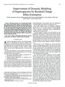
Figure 1. Abstract Model of Web applications In this paper, we propose a lightweight UML-based approach to modeling small and medium sized Web applications aiming at the above requirements. The approach employs use case diagrams, activity diagrams and class diagrams in order to capture the fundamental structural and behavioral aspects of a Web application while providing different views on these aspects according to the needs of different team members. Using our running example of an online reservation system we shall demonstrate the derivation of code templates in HTML and PHP from use case and activity diagrams.
diagram specifying navigational nodes and links. The presentation model defines the structure of the user interface by means of composite objects and their dynamic behavior by state diagrams. Further, presentation objects are used to describe the concrete layout of the user interface. Such an approach is useful for fullscale applications with a complex user interface, but seems to be oversized for small applications whose interface consists of simple HTML pages. Our modeling approach focuses on those aspects that are important for the cooperation between developers, graphic designers, and domain experts, leaving user interface design and layout to the graphic designer.
2. RELATED WORK
The Web Modeling Language (WebML) [3] is a notation for specifying complex Web sites at a conceptual level. It distinguishes between a structural model, a composition model, and the topology of links between pages. Further, WebML lets you define layout and graphics requirements for page rendering and includes a personalization model. WebML also addresses the issue of different kinds of specialist playing different roles.
In this section, we briefly discuss different approaches to the modeling of Web applications. Some focus on the modeling notation, like Conallen who proposes an extension to the UML. Other focuses on the development process, for example [2], WebML or WSDM. Conallen [4,5] defines a UML profile for Web application design. He introduces stereotypes for components, classes, methods and associations in order to distinguish, for example, server components, client components, server pages, etc. The approach covers the modeling of layout and implementation aspects. Baumeister, Koch and Mandel [2] are describing a hypermedia extension to the UML to model Web applications, focusing on the navigation and the user interface. The conceptual model consists of a class diagram identifying the objects of the problem domain and their relations. The navigation structure is described by a class
WSDM (Web Site Design Method) [6] is a user centered approach. The starting point is a set of potential visitors of a Web site which are classified into user classes. The available data is modeled on the basis of the information requirements of the users. WSDM describes a process consisting of four phases: user modeling, conceptual design, implementation design, and implementation. The user modeling phase consists of two subphases, the user classification and the user class description. With the user classification the audience of the Web site are identified
and classified. Different user classes perform different activities on the Web site. The user class description contains information requirements and the characteristics of the user classes. The conceptual design phase consists of the two sub-phases of object modeling and navigational design. Within object modeling the information requirements of different user classes with their different perspectives are formalized. How the different users can navigate through the Web site is described within the navigation model. This method defines its own graphical notation for the objects of the navigation model and does not distinguish different views for designer and application developer.
such data exists, the renderer produces always the same client page and could be replaced by a corresponding static page.
3.2 Modeling In order to support the capturing and presentation of requirements, use case diagrams are employed. They describe the fundamental functional aspect of the system from the perspectives of different users. We will use a simple example to illustrate our approach. This example is a hotel reservation system. The system provides the usual functionality of placing and cancellation a reservation and includes views for both the guest and the hotel clerk. Figure 2 shows the use case diagram for this system.
3. DESIGN METHODOLOGY 3.1 A Conceptual Model for Web applications Small and medium size Web applications are usually based on dynamic Web pages using server side scripting. Figure 1 shows an abstract model for such a Web application. All interactions in these Web applications are based on Web pages. We have to distinguish between a client page and the server page generating the client page. For a static page, the client page is a simple client side copy of the server page. In the case of a dynamic page, the client page is being computed by a server side program. Such a program is usually a script realized using some scripting language like PHP, JSP or ASP. This script generates the client page to be displayed by the client. A client page may contain links to different server pages. The activation of such a link may transmit data, i.e., as a HTML form or URL-encoded, to a dynamic page. This data is used by the dynamic page to compute a new client page. Thus, the business logic is contained in the dynamic pages on the server side. Currently, many small- and medium size Web systems suffer from the confusion of presentation and business logic in the code modules. These systems are implemented very straightforwardly using monolithic scripts. But certain parts of the business logic are relevant for more than one dynamic page. Let us consider the example of a hotel reservation system where a business logic module computes the price for a room reservation. This module may be relevant for both a dynamic page offering to place the reservation as well as a dynamic page that is used for execution of the confirmed reservation. This raises the need for reuse of the business logic. Such a reuse is common sense for normal software development but for Web development this is still an important issue. In order to allow this reuse, we have encapsulated the business logic of the dynamic Web pages into processor modules. One such processor module can be associated to multiple dynamic pages thus supporting reuse. In our example, the processor implementing the business logic for computing the price for a reservation would be associated to both dynamic pages mentioned above. The separation of the business logic also enables independent presentation of the computed data. This allows changing the presentation without changing the logic. A separate renderer module is used to compute the complete client page. However, the renderer is not intended to compute any other function on the data, which would belong to the business logic located in the processor associated to the dynamic page. The data used by the renderer will usually be produced by a subset of the processors using input data from links and persistent data. In cases where no
Reservation System
Cancel Reservation
Guest
Place Reservation «include» «include» Manage Reservations
Clerk
Figure 2. Reservation System - use case diagram Since the use case diagrams will later be used for code generation, we introduce additional semantics which influence the use of these diagrams. The root use case diagram is intended to provide the initial views of the system’s functionality that will be displayed on the starting pages for the respective actor. The actors represent different roles for users of the Web application. In our example, the clerk may act like a guest, e.g., to execute the guest’s orders, or perform administrative work that is not intended to be done by guests. This is a very usual and general distinction which can be found on almost any Web application. In our approach, a use case has to be detailed by an activity diagram or other Use Cases (possibly in a different use case diagram). Thus, at the lowest level all Use Cases are described by activity diagrams. Such an activity diagram will describe the interactions between client and server pages as well as possible user decisions on the client side. Figure 3 shows the activity diagram detailing the “Place Reservation” use case from the use case diagram above. The activity diagram detailing a use case has three areas. Swimlanes separate client and server from the communication. Only object flows and control flows are valid model elements for the communication area. In the client and server areas, we use stereotyped actions according to the conceptual model (see Figure 1). «ClientPage» and «Link» are the only valid action stereotypes for the client side, as «Processor» and «Renderer» are for the server side. Thus, dynamic pages will be modeled as subactivity graphs containing invocations of the associated renderers and processors as action states. Choice nodes may be used to evaluate the return value from a processor and make a decision between different execution flows. These execution flows may end in different renderers. The business logic will be contained in action states, which have to be detailed to provide the actual implementation of a certain action.
Figure 3. Place Reservation activity diagram To extract the server side subgraph related to a dynamic page, the graph has to be traced from an incoming control- or object flow to all reachable renderers. The client side subgraph can be found by tracing from all the renderers in the server side subgraph to the links. These two subgraphs are the basis for the code generation from the activity diagram, as they contain the description of both the behavior and the structure of a dynamic page. The necessary data information can be extracted from the type definition of the instances in the object flow.
code generation. Therefore, the objects in these object flows are assumed to be in a composite state according to the state chart diagram shown in Figure 5. The state also reflects the persistence of the object. Persistent objects allow the generation of pure references in cases when data is only intended for parameter passing to the next activity.
A class diagram will be used for the description of the data processed by the Web application. This diagram shows the structure and composition of both transient and persistent data. All data passed in the activity diagrams using object flows has to be typed consistently with this class diagram. Figure 4 shows the part of the class diagram for our reservation example, which is relevant to our example use case “Place Reservation”. Reserv ation +
Price: Currency
Reserv ationData + + + +
Start: Date End: Date NumSingle: Integer NumDouble: Integer
Figure 4. Part of the Reservation System class diagram
Figure 5. Data Flow Object State
It is important to distinguish between display data and editable data in the object flows. This information is essential for later
To add business logic details to an activity diagram, the «Processor» actions can be detailed using a subactivity diagram.
This diagram may contain action states as well as object flows that are typed consistently with the class diagram. Actions in this diagram may be detailed by a diagram of the same kind. Decisions can evaluate the return values of the preceding action states. For the subactivity diagram related to those action states, the name of last action state visited will be considered as the return value to the parent activity diagram. Figure 6 shows the subactivity diagram refining the «Processor» Reservation action from the activity diagram shown in Figure 3. Although the structural information is partially implicit in the activity diagrams, jointly these models form a complete structural and behavioral description of those parts of the Web application which are needed for the communication within the development team and with the customer. Furthermore, the model can be used for code generation leading to rapid prototyping from the model.
pages to test the whole Web application, consisting of static and dynamic web pages, before the design of the Web application is complete. For example, from the use case diagram in Figure 2 two static HTML pages are obtained. The static HTML page generated for the clerk consists of three links. All three links are starting a script. The following HTML extract is an example for a possible generated starting page of the clerk. Observe that a generated link either points to static HTML page or a script. A script has to be used, if the refining activity diagram does not start with a static page. Clerk
Starting page for clerk
Cancel Reservation