of a circuit's dc operating points, may or may not af- fect the value of the .... If none of the three resistors is short-circuited, the feed- back structure is present. Note ...
Limitations of Criteria for Testing Transistor Circuits for Multiple DC Operating Points Lars Kronenberg and Wolfgang Mathis Department of Electrical Engineering, University of Magdeburg, 39016 Magdeburg, Germany
Ljiljana Trajkovi´c School of Engineering Science, Simon Fraser University, Burnaby, British Columbia, Canada V5A 1S6
Abstract
— In this paper we address the problem of determining whether a transistor circuit possesses multiple dc operating points. We investigate how the sign change of the determinant corresponding to the Jacobian matrix associated with circuit equations can be used to indicate the number of dc operating points in a transistor circuits. We give circuit examples that illustrate that these criteria may not be reliable, and show that resistor values that determine the number of a circuit’s dc operating points, may or may not affect the value of the calculated determinant. Even if the mere existence of a feedback structure depends on whether a particular resistor is open- or shortcircuited, the resistor value may not affect the value of the determinant. Hence, the determinant criteria is not always indicative of the number of a circuit’s dc operating points. I. Introduction The mathematical problem of finding a nonlinear circuit’s dc operating points is described by a set of nonlinear algebraic equations constructed by applying Kirchhoff’s voltage and current laws, and by employing the characteristics of the circuits elements. Common numerical approaches for finding these operating points (e.g., Newton-Raphson method) require that the starting point of a numerical process be close enough to the unknown solution. Hence, in order to apply these methods, it is necessary to determine: • the existence of multiple dc operating points • a good starting point for each solution that need to be found. Both problems are difficult and remain unsolved. In this paper we address the problem of finding a reliable criteria to determine whether a circuit possesses multiple dc operating points. Although we confine our analysis to bipolar-transistor circuits, our findings are also applicable to other types of transistor circuits. Purely topological approaches for finding whether a circuit possesses multiple dc operating points, such as detecting the presence of feedback structures [6] that we briefly
describe in Section II., are not sufficient. Another approach, the determinant criteria described in Section III., based on the change of sign of the determinant of the Jacobian matrix [14], does not take into account the contribution of sources because their values do not appear in the expression for the determinant [3]. We examine in more details this approach, and in Section IV. we give circuit examples that illustrate that these criteria cannot reliably indicate the number of a circuit’s dc operating points.
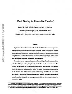
II. TOPOLOGICAL APPROACH One approach to qualitatively analyze circuits is to consider only the circuit’s topology, i.e., only the way circuit’s elements are connected together. Nielsen and Willson have discovered [6] a unique topological structure, called feedback structure, that may cause multiple dc operating points in transistor circuits. Such a structure, consisting of bipolar transistors, is shown in Fig. 1.
a
b
c
d
e
f
6-terminal-circuit Fig. 1. Feedback structure consisting of two bipolar transistors. The remaining of the circuit is represented as a black box. The type of the transistors (n type or p type) is irrelevant.
Presence of at least one feedback structure is necessary if a transistor circuit is to possess multiple dc operating points [6]. Unfortunately, this is only a necessary condition. Even if a feedback structure is present, the circuit may or may not possess multiple dc operating points, depending on circuit parameters and biasing conditions [9]–[11].
III. JACOBIAN DETERMINANT CRITERIA Circuit equations for a transistor circuit consisting of p transistors and q diodes, can be written in the from [15]:
where
QTF(v) + Pv + c = 0,
(1)
f1 (v1 ) .. F(v) := . f2p+q (v2p+q )
(2)
and fi (vi ) are monotone increasing functions of the form fi (vi ) = mi (eni vi − 1).
(3)
Matrices P, Q, and T are constant matrices of order (2p+ q) × (2p + q). T is a block-diagonal matrix whose first p blocks are 2 × 2 block matrices of the form � � 1 −αr{2i} , 1 ≤ i ≤ p, (4) −αf{2i−1} 1 followed by q 1 × 1 blocks, each equal to 1. The controlled-source current-gains satisfy condition 0 ≤ αf{2i−1}, αr{2i} < 1. The corresponding circuit may possess multiple dc operating points only if the determinant of the Jacobian matrix can change its sign. We refer to this test as the “determinant criteria.” The Jacobian matrix of (1) is J = QTD + P,
(5)
where D is a diagonal matrix consisting of the derivatives of the nonlinear function F(v). In case of a two-transistor circuit, its determinant can be decomposed as [5]: det(QTD + P) = c1234d1 d2 d3 d4 + c123d1 d2 d3 + c124 d1 d2 d4 + ... + c12 d1 d2 + ... + c1 d1 + ... + c0 d0 ,
(6)
where di ≥ 0, i = 1, 2, 3, 4, if all fi (v) in F(v) are monotone increasing functions. In case of a two-transistor circuit, matrices P and Q in (1) can be chosen so that all coefficients cs , except possibly one coefficient associated with a specific feedback structure, are nonnegative [5]. We will call the “coefficient criteria” the test whether such a coefficient is negative for a specific choice of circuit parameters. IV. EFFECT OF RESISTORS ON THE VALUE OF THE COEFFICIENTS A crucial question when applying the determinant and the coefficient criteria is their reliability. Hence, we revisit here these two criteria and we investigate whether the determinant (6) and the sign of the coefficients cs can
be used to reliably indicated changes in the number of a circuit’s dc operating points caused by a change of a resistor’s value. In other words, we pose the question: Can every change in the number of dc operating points be detected by these two criteria? In order to evaluate the reliability of the coefficient criteria, we employ the results that the presence of a feedback structure is necessary for the existence of multiple dc operating points [6]. We distinguish two topological cases: • The presence of a feedback structures does not depend on the resistor’s value, i.e., open-circuiting or short-circuiting a resistor does not affect the feedback structure. • At least one feedback structure gets created or it vanishes if a particular resistor is either open-circuited or short-circuited. Based on these two cases, we construct circuit examples to illustrate the failure of the coefficient criteria to predict the circuit’s behavior. A. Example 1: Resistor values do not affect the value of a coefficient used to test the circuit for multiple dc operating points. The presence of a negative differential resistance (NDR) that may be observed across one-ports formed from the original circuit, is intimately related to the number of the circuit’s dc operating points. The existence of NDR indicates that the circuit may possesses multiple dc operating points for an appropriate choice of the values of independent current or voltage source. Examples how circuits parameters and biasing affect the occurrence of NDR in two-transistor circuits are given in [9]–[11]. In [11], it was shown that resistor values do not necessarily cause more prominent NDR behavior, even if they cause a more prominent feedback structure. Based on examples reported there, we created the example shown in Fig. 2. For this circuit, matrices defined in (1) are: 0 0 0 0 0 0 0 0 Q= 1 1 0 −1 0 −1 1 1 1 −1 −1 0 V 0 0 1 0 1 P= G2 G3 G1 −G1 c = 0 . 0 0 0 G3 0
It has been found that for a two-transistor circuit, only one term in the determinant (6) may be negative [4], [5]. For the feedback structure where two emitters are connected to each other, the only possibly negative coefficient
B. Example 2: Coefficient used to test the circuit for multiple dc operating points does not indicate the disappearance of a feedback structure.
v3
Q2
v4 G1
There are two general ways to destroy a feedback structure. By
G3 V
• opening of one of the three paths between the transistors, or
v2
G2
• short-circuiting connections between two of the three paths in the feedback structure.
Q1
v1
Fig. 2. S-type NDR circuit: if present, the feedback structure causes the circuit to exhibit NDR if values of conductances are appropriately chosen. Any two of the three resistors may be open-circuited. The NDR disappears if all three resistors are open-circuited, even though the feedback structure exists.
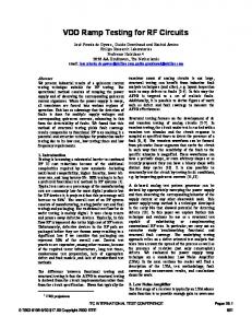
We show now that the value of the only possibly negative coefficient in determinant (6) fails to indicate that a feedback structure vanishes. The circuit example is shown in Fig. 3. v3
Q2
v4
is c13 . This coefficient can be obtained by calculating the determinant of a matrix formed by taking the 1st and the 3rd column from matrix QT, and all the remaining columns from matrix P: 0 0 C= 1 − αf1 αf1
−1 1 G3 0
0 0 αf3 1 − αf3
v4 V R6
V
v3
Q2
0 1 . −G1 G3
R4
R3
R5 v2
v2 Q1
v1
Q1
v1
Then, c13 := det(C) = 1 − αf1 − αf3 < 0,
Fig. 3. The coefficient criteria may fail to predict the presence of a feedback structure (left), or it may successfully do so (right).
if αf1 > 0.5 and αf3 > 0.5, which holds for realistic transistor parameters. Based on this criteria, we may conclude that the circuit may possess multiple dc operating points. If none of the three resistors is short-circuited, the feedback structure is present. Note, however, that the values of three conductances G1 , G2 , and G3 do not affect the value of the coefficient c13 . Hence, its sign fails to indicate how the values of the resistors affect the number of transistors’ dc operating points. For example, it can be easily verified by SPICE simulations [7], [8] that the circuit exhibits:
Equations for the circuit on the left are defined by matrices: 0 −R5 0 0 0 R5 0 R4 Q= 1 1 0 −1 0 −1 1 1 1 −1 −1 0 V 0 1 0 0 1 P= c= 0 0 0 . 0 0 0 0 0 0 0
• NDR behavior [1], [2], [13], and hence possesses multiple dc operating points, for G1 = G2 = 0 and G3 = 0.02 S, and for G1 = G3 = 0 and G2 = 0.0033 S. • no NDR behavior [12], [13], and hence possesses a unique dc operating point, for G1 = G2 = G3 = 0. Nevertheless, the value of the one possibly negative coefficient c13 is not affected by the resistor values.
This circuit has an emitter-emitter feedback structure, and the only possibly negative coefficient is c13 . It can be calculated by first forming matrix C by taking the 1st and the 3rd columns of matrix QT, and the remaining columns from P: αf1 R5 −1 0 0 −αf1 R5 1 −αf3 R4 1 . C= 1 − αf1 0 αf3 0 αf1 0 1 − αf3 0 Hence, c13 := det(C) = 1 − αf1 − αf3 < 0
if αf1 > 0.5 and αf3 > 0.5, which is the case for realistic values of transistor parameters. Note, however, that although the feedback structure vanishes if one of the resistors (R4 or R5 ) is open-circuited, this determinant, being independent of R4 and R5 , fails to indicate that. Unfortunately, even this result can not be generalized, as illustrated by the example of Fig. 3 (right). For this circuit: 0 0 0 0 0 0 0 0 Q= 0 R3 −R3 −R3 R6 0 R6 0 1 −1 −1 0 V 0 1 0 0 1 P= c= 0 1 0 . 0 0 1 0 0 0 0 Again, matrix C is formed by taking the 1st and the 3rd columns from QT, and the remaining columns from P: 0 −1 0 0 0 1 0 1 C= −αf1 R3 1 −(1 − αf3 )R3 0 . R6 0 R6 0 Hence, c13 := det(C) = R3 R6 (1 − αf1 − αf3 ). This coefficient vanishes if R3 = 0 and/or R6 = 0. Hence, we conclude that appropriate values of R3 and R6 may cause multiple dc operating points, as correctly indicated by the sign of the coefficient c13 . V. CONCLUDING REMARKS In this paper we re-examined the effect of a circuit’s resistors on the value of certain determinants and coefficients that can be used to predict whether a circuit may possess multiple dc operating points. Using example circuits, we showed that changes in the number of dc operating points that may be caused by resistor values, cannot always be indicated by the coefficient criteria. This finding holds no matter whether or not the existence of a feedback structure is affected by the change in the resistor values. Even though the resistors’ values affect the entries of matrices P and Q in (6), the coefficient criteria do not necessarily indicate a change in the number of dc operating points caused by resistor values. It has been known that the determinant criteria are not sufficient to reliably indicate the number of a circuit’s dc operating points [10], [11]. The reason is that they take into account neither values of dc sources [3], nor the exact
values of the nonlinearities fi (vi ) in (2), that ultimately affect the value of the Jacobian determinant (6). Therefore, they ignore the actual values of di in (6), which are determined by transistors’ biasing, and play an essential role in a circuit’s capability to possess multiple dc operating points. Even if it is possible to force the Jacobian determinant (6) to becomes negative, the biasing necessary for this to happen may be impossible for realistic transistor circuits. This biasing information is ignored by the determinant and the coefficient criteria. References [1] L. O. Chua, J. B. Yu, and Y. Y. Yu, “Negative resistance devices,” Int. J. Circuit Theory and Appl., vol. 11, pp. 161– 186, April 1983. [2] L. O. Chua and A. C. Deng, “Negative resistance devices: part II,” Int. J. Circuit Theory and Appl., vol. 12, pp. 337–373, Oct. 1984. [3] L. Kronenberg, Lj. Trajkovi´ c, and W. Mathis, “Finding dc operating points: limitations of topological and determinant criteria,” to be presented at NOLTA ’2000, Dresden, Germany, Sept. 2000. [4] B. G. Lee and A. N. Willson, Jr., “All two-transistor circuits possess at most three dc equilibrium points,” Proc. 26th Midwest Symp. Circuits and Systems, Puebla, Mexico, Aug. 1983, pp. 504–507. [5] B. G. Lee and A. N. Willson, Jr., “On a determinant expansion in the theory of two-transistor circuits,” IEEE Trans. Circuits Syst., vol. 37, pp. 864–866, June 1990. [6] R. O. Nielsen and A. N. Willson, Jr., “A fundamental result concerning the topology of transistor circuits with multiple equilibria,” Proc. of the IEEE, vol. 68, no. 2, pp. 196–208, Feb. 1980. [7] PSpice: http://www.orcad.com/Product/Analog/Analog.asp. [8] T. L. Quarles, A. R. Newton, D. O. Pederson, and A. Sangiovanni-Vincentelli, “SPICE 3 Version 3F5 User’s Manual,” Department of EECS, University of California, Berkeley, March 1994. [9] Lj. Trajkovi´ c and A. N. Willson, Jr., “Circuit parameters and the occurrence of negative differential resistance,” Proc. IEEE Int. Symp. Circuits and Systems, San Jose, CA, May 1986, pp. 277–280. [10] Lj. Trajkovi´ c and A. N. Willson, Jr., “Biasing of two-transistor circuits exhibiting negative differential resistance,” Proc. 29th Midwest Symposium on Circuits and Systems, Lincoln, NE, Aug. 1986, pp. 158–162. [11] Lj. Trajkovi´ c and A. N. Willson, Jr., “Behavior of nonlinear transistor one-ports: things are not always as simple as might be expected,” Proc. 30th Midwest Symposium on Circuits and Systems, Syracuse, NY, Aug. 1987, pp. 1210–1213. [12] Lj. Trajkovi´ c and A. N. Willson, Jr., “Replacing a transistor with a compound transistor,” IEEE Trans. Circuits Syst., vol. CAS-35, pp. 1139–1146, Sept. 1988. [13] Lj. Trajkovi´ c and A. N. Willson, Jr., “Complementary twotransistor circuits and negative differential resistance,” IEEE Trans. Circuits Syst., vol. 37, pp. 1258–1266, Oct. 1990. [14] A. N. Willson, Jr., “New theorems on the equations of nonlinear dc transistor networks,” Bell Syst. Tech. J., vol. 49, pp. 1713–1738, Oct. 1970. [15] A. N. Willson, Jr. (Editor), Nonlinear Networks: Theory and Analysis. New York, NY: IEEE Press, 1975.