resonance in microelectromechanical systems (MEMS) was first proposed for .... drives to tune an oscillator's effective linear and nonlinear stiff- ness coefficients ...
310
JOURNAL OF MICROELECTROMECHANICAL SYSTEMS, VOL. 16, NO. 2, APRIL 2007
Linear and Nonlinear Tuning of Parametrically Excited MEMS Oscillators Barry E. DeMartini, Student Member, IEEE, Jeffrey F. Rhoads, Student Member, ASME, Kimberly L. Turner, Member, IEEE, Member, ASME, Steven W. Shaw, Fellow, ASME, and Jeff Moehlis
Abstract—Microelectromechanical oscillators utilizing noninterdigitated combdrive actuators have the ability to be parametrically excited, which leads to distinct advantages over harmonically driven oscillators. Theory predicts that this type of actuator, when dc voltage is applied, can also be used for tuning the effective linear and nonlinear stiffnesses of an oscillator. For instance, the parametric instability region can be rotated by using a previously developed linear tuning scheme. This can be accomplished by implementing two sets of noninterdigitated combdrives, choosing the correct geometry and alignment for each, and applying ac excitation voltages to one set and proportional dc tuning voltages to the other set. Such an oscillator can also be tuned to display a desired nonlinear behavior: softening, hardening, or mixed nonlinearity. Nonlinear tuning is attained by carefully designing combdrive geometry, flexure geometry, and applying the correct dc voltages to the second set of actuators. Here, two oscillators have been designed, fabricated, and tested to prove these tuning concepts experimentally. [2006-0085] Index Terms—Electrostatic, noninterdigitated combrives, nonlinear, parametric resonance, tuning. Fig. 1. Representative first parametric region of instability in excitation voltage amplitude V versus nondimensional frequency space.
I. INTRODUCTION ECENTLY, microelectromechanical oscillators exploiting parametric resonance have been shown to have benefits over conventional linear based micro-oscillators. Parametric resonance in microelectromechanical systems (MEMS) was first proposed for amplification of harmonically excited oscillators in [1], and since then parametric excitation has been investigated for increasing sensitivity in scanning probe microscopy [2] and mass sensing [3]. Common MEMS exhibiting nonlinearities that lead to this type of resonant behavior include translational [3], [4], torsional [2], and cantilever [1], [5] devices. Parametric resonance has also been found in nanoscale oscillators, specifically nanowires [6]. Characteristic to all of these oscillators is the ability to resonate when driven at , where is an integer greater than or frequencies near 2 is the natural frequency [7]. Of interest equal to one and in this paper is the oscillator’s primary parametric resonance , where the oscillator is driven region, corresponding to
R
Manuscript received May 8, 2006; revised November 13, 2006. This work was supported by the U.S. Air Force Office of Scientific Research under Contract F49620-02-2-0069 and the National Science Foundation under Grant NSF0428916. Subject Editor G. Fedder. B. E. DeMartini, K. L. Turner, and J. Moehlis are with the Department of Mechanical Engineering, University of California, Santa Barbara, Santa Barbara, CA 93106 USA. J. F. Rhoads and S. W. Shaw are with the Department of Mechanical Engineering, Michigan State University, East Lansing, MI 48824 USA. Digital Object Identifier 10.1109/JMEMS.2007.892910
near twice its resonant frequency. Driving an oscillator in this manner results in a wedge-shaped instability region, such as that shown in Fig. 1, where the oscillator remains motionless outside the wedge and transitions sharply to (relatively) large amplitude oscillatory motion inside the wedge. It is these sharp transitions that make this class of oscillators attractive for many applications. One of the more recent applications proposed for parametric resonance is single frequency bandpass filtering [8], [9]. In order for this technology to be applied to filtering, both linear and nonlinear tuning techniques are necessary to achieve the desired frequency response characteristics [4], [10]. In this paper, two oscillators are designed, fabricated, and tested in order to demonstrate the tuning concepts developed in [9]. Specifically, a linear tuning scheme is used to rotate the instability region and a nonlinear tuning scheme is used to achieve desired hardening or softening behavior in the system’s response. A single frequency filter, utilizing these tuning concepts, has been successfully realized with simulations [9]. Despite this paper’s emphasis on filtering applications, the tuning methods can be leveraged in any application where the dynamics inherent to parametric oscillators need to be manipulated (e.g., resonant mass sensors based on parametric resonance [3]). Additional techniques that have been developed that allow for frequency tuning of general MEM oscillators include localized thermal stressing of mechanical beam structures [11], power dissipation through filament annealing [12],
1057-7157/$25.00 © 2007 IEEE
DEMARTINI et al.: LINEAR AND NONLINEAR TUNING OF PARAMETRICALLY EXCITED MEM OSCILLATORS
311
and are, respectively, the linear and nonlinear where electrostatic stiffness coefficients due to the dc excited elecand are, respectively, the linear and nonlinear trodes, electrostatic stiffness coefficients due to the ac excited elecand are, respectively, the applied dc and ac trodes, and signal amplitudes. It is important to note that the oscillator is driven with a square root cosine signal, giving rise to the ac forcing term in (1), in order to demodulate harmonic and parametric excitation [2]. A restoring force is generated by the flexures (2)
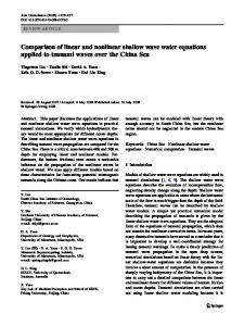
Fig. 2. Scanning electron image of a parametrically excited MEM oscillator with noninterdigitated driving and tuning combdrives (A and B), flexures (K), and backbone (M).
resistive heating to induce thermal strains in MEM resonators [13], and electrostatic tuning for parallel plate capacitor and combfinger driven oscillators [14]–[17]. Tuning techniques will aid in the design and implementation of a wide variety of MEM devices. In Section II, the governing equation of a tunable parametrically excited MEM oscillator with linear and nonlinear time-varying stiffness terms, commonly referred to as a nonlinear Mathieu equation, is described. The addition of the nonlinear time-varying stiffness term included here and in [3] and [18] results in interesting dynamics, which differ from those of Mathieu oscillators containing only linear time-varying stiffness terms [19]. In Section III the linear tuning scheme is reviewed, the design for two MEM devices is discussed, and experimental results obtained for each device are presented and discussed. Section IV has the same structure as Section III but for the case of nonlinear tuning. Concluding remarks are given in Section V. II. DYNAMICS OF A TUNABLE PARAMETRIC MEM OSCILLATOR This type of oscillator consists of a backbone (M), noninterdigitated combdrives (A and B), and flexures (K). A standard silicon-on-insulator process is used to fabricate the representative device shown in Fig. 2. This paper utilizes two sets of noninterdigitated combdrives: one for actuation and one for tuning. In [4], the concept of using a set of dc noninterdigitated combdrives to tune an oscillator’s effective linear and nonlinear stiffness coefficients is presented. Here oscillators are driven by applying an ac signal to a driving set of electrodes and tuned by a dc signal that is applied to a second set of electrodes. The tuning scheme used in this paper has been analyzed theoretically in [9] and will be reviewed in sections to follow. The electrostatic force produced by these noninterdigitated drives is modeled as a cubic function of displacement [3]
(1)
where and are, respectively, the linear and cubic nonlinear stiffness coefficients. Note the restoring force is also accurately modeled as a cubic function of displacement, for which the cubic nonlinear stiffness is generally mechanically hardening . Combining (1) and (2) along with the force due to aerodynamic damping gives the equation of motion [9]
(3) is the oscillator’s where is the damping coefficient and mass. For analytical purposes (see [9] and [18]), the time in the equation of motion is rescaled according to (4) where
is the pure elastic natural frequency (5)
and displacement is rescaled according to (6) is a characteristic length, where is a scaling parameter and e.g., the length of the oscillator backbone (note this is the scaling adopted in [9]). As in [18], displacement can also be scaled acand the scaling parameter can be introcording to duced by assuming that nondimensional damping, electrostatic forces, and mechanical nonlinearities are small. In either case, the rescaled equation of motion becomes
(7) Table I describes each parameter and the derivative operator of (7); also see [18] and [9]. Equations (3) and (7) are generalizations of the Mathieu equation. Specifically, both linear and nonlinear stiffness terms vary with time, whereas the conventional Mathieu equation only contains linear time-varying stiffness terms, e.g., [19]. The presence of nonlinear parametric excitation leads to interesting dynamics, which have been accurately modeled in [18]. In this analysis, averaged equations were determined for (7) through a perturbation technique and steady-state solutions to these averaged equations were determined. By analyzing the stability of the trivial solution, a boundary for the primary parametric stability
312
JOURNAL OF MICROELECTROMECHANICAL SYSTEMS, VOL. 16, NO. 2, APRIL 2007
TABLE I NONDIMENSIONAL PARAMETER AND OPERATOR DESCRIPTIONS FOR (7)
region can be determined; Fig. 1 depicts a representative stability boundary. The nontrivial solutions to the averaged equations represent different branches of the system’s response and ultimately allow for effective nonlinearities to be defined. In the end, the qualitative behavior of the system’s response is determined by these effective nonlinearities. These analytical results are instrumental in the design portion of this paper.
Fig. 3. Noninterdigitated combfinger and flexure geometries. (a) Aligned, (b) misaligned, (c) fixed–fixed, (d) crableg.
The oscillator’s nondimensional time-independent natural frequency now depends on excitation amplitude (12)
III. LINEAR TUNING For applications such as filtering, having an amplitude-dependent bandwidth (as in Fig. 1) is undesirable. As a result, a method for tuning this wedge shaped region has been developed [9] and is briefly reviewed here. Specifically, the system’s natural frequency is forced to depend on the excitation . This is accomplished by applying a voltage amplitude dc voltage , which is proportional to the ac voltage ampli), to a second set of noninterdigitated tude (i.e., combdrives. The linear and nonlinear stiffness coefficients are redefined as (8) (9)
With the introduction of the new parameter comes the ability to tune the system’s instability region. Specifically, as changes, therefore changing , the natural frequency changes. As a result, by choosing the correct magnitude and sign for and sign for , the instability region in Fig. 1 can be rotated clockwise or counterclockwise to a specific location [9]. For filtering applications, tuning the wedge-shaped region to have a vertical, frequency-independent boundary is desirable. Perturfor bation analysis used in [9] shows that by choosing (or for ), the left boundary of the instability zone is rotated to the vertical position. Likewise, the right boundary can be tuned to the vertical position by choosing for (or for ). As detailed in [9], the implementation of two tuned oscillators (one with and another with ) in a single system can render a highly effective single frequency bandpass filter. A. Designing Linear Tunable Oscillators
respectively. Next, a tuning parameter is introduced (10) Linearizing about the no-motion state and rewriting in the form , (7) becomes (11)
Noninterdigitated combdrives and flexures can be designed to achieve specific linear tuning characteristics. The main concern for designers, however, is the geometry of the combdrives only changes in because the linear mechanical stiffness magnitude for different flexure designs. The geometric factors affecting electrostatics between combfingers are spacing, gap, length, width, and alignment [depicted in Fig. 3(a) and (b)]. For details on how combfinger geometry affects the electrostatic coefficients, refer to [4]. For design purposes, the
DEMARTINI et al.: LINEAR AND NONLINEAR TUNING OF PARAMETRICALLY EXCITED MEM OSCILLATORS
313
TABLE II OSCILLATOR DESIGN DESCRIPTIONS AND COEFFICIENTS (SEE FIG. 3 FOR LABELED GEOMETRIES)
Fig. 5. Misaligned combdrive force-displacement relationship determined using ANSYS for Device 1 (x’s) and Device 2 (o’s). The polynomials are fit to these data to determine linear and cubic nonlinear stiffness coefficients (solid curves).
Fig. 4. Aligned combdrive force-displacement relationship determined using ANSYS for Device 1 (x’s) and Device 2 (o’s). The polynomials are fit to these data to determine linear and cubic nonlinear stiffness coefficients (solid curves).
multiphysics environment in ANSYS is used to determine the force-displacement relationship for different combdrive geometries. To achieve rotation of the instability regime in a desired direcand tion, (10) is considered. Specifically, the coefficients must be of opposite sign to rotate the wedge and achieve verticality of either boundary, which is of interest here. Of course the ratio can be chosen to be positive; however, then vertical bound, then the instability zone aries cannot be achieved. If
bends off to the right and the introduction of a negative effectively rotates the wedge counterclockwise. On the other hand, , a positive rotates the wedge clockwise. In either for case, the magnitude of dictates how far the wedge rotates and whether the right or left boundary of the wedge is vertical. Here, two oscillators have been designed, both having a combfinger width of 1.5 m, combfinger gap of 1 m, combfinger spacing of 10 m, and combfinger length of 8 m (Table II). It turns out that aligned combfingers [Fig. 3(a)] having this geometry exhibit a positive linear electrostatic stiffness and misaligned combfingers [Fig. 3(b)] exhibit a negative linear electrostatic stiffness. Therefore, by designing one pair of combdrives to be aligned and one pair of combdrives to be misaligned, the oscillators’ parametric regions of instability can be tuned with the scheme presented in [9] (reviewed above). The two oscillator designs are discussed in Table II. It is important to note that Device 1 has 160 aligned combfingers, 164 misaligned combfingers, and an effective mass of approximately 5.95 10 kg, while Device 2 has 128 aligned combfingers, 130 misaligned combfingers, and an effective mass of approximately 4.89 10 kg. The force-displacement relationships, determined from finite element analysis, for each design’s aligned and misaligned combdrives are shown in Figs. 4 and 5, respectively. For Device 1, the linear electrostatic stiffness coefficient is positive, so that the wedge shaped instability region bends off toward the right. For proof of concept of the theory presented in [9], the right instability boundary of this device was chosen to , the tuning parameter should be made vertical. Since and the applied dc and ac voltages should be be from (10). related by the proportionality constant Device 2, on the other hand, has , so that the wedge bends off toward the left. In this case, the goal was to rotate the left stability boundary to the vertical position, so should be chosen and the dc and ac voltages should be related by . Flexure designs are discussed in the nonlinear tuning design section of this paper because the magnitude of the linear mechanical stiffness does not strongly affect the linear electrostatic
314
JOURNAL OF MICROELECTROMECHANICAL SYSTEMS, VOL. 16, NO. 2, APRIL 2007
Fig. 6. Experimental untuned (o’s) and tuned (x’s) instability zones for (a) Device 1 and (b) Device 2. An ac signal is applied solely to the driving set of combfingers for the untuned wedges and both dc and ac signals are applied to the respective combdrives for the tuned wedges. Tuning coefficients for each case are (a) � = 1:66 and (b) � = 0:42.
, the clockwise. Tuning with a proportionality constant left boundary has been tuned roughly to the vertical position. Again the misaligned combfingers exhibit a negative linear electrostatic stiffness, while aligned combfingers exhibit a positive linear electrostatic stiffness for the geometry presented in Section III-A. In both cases, the linear electrostatic stiffness for the driving and tuning sets of combfingers are of opposite sign, therefore allowing an to be chosen that rotates the right (Device 1) or left (Device 2) stability boundary roughly to the vertical position. Experimental values for Device 1 and Device 2 both compare well with theoretically obtained values, especially considering the amount of uncertainty in the dimensions of the fabricated devices. These results prove the concepts proposed in [4] and [9]. Since proof of concept is the main goal here, a system identification procedure has not been performed. If system parameters needed identification, however, methods similar to those discussed in [21] could be adopted. Also, it is important to note that more testing and finer tuning of can yield better verticality if desired for specific applications, i.e., filtering, where a frequency-independent boundary is desired. IV. NONLINEAR TUNING
tuning of the instability region. It is important, however, to point out that Device 1 and Device 2 have different flexure configurations (crableg and fixed–fixed, respectively), different flexure lengths, and different effective masses, so each has a different resonant frequency. Fig. 2 shows a scanning electron image of Device 2 with fixed–fixed flexures. B. Experimental Results Parametrically excited MEM oscillators have successfully been tuned by applying a dc voltage to a second set of noninterdigitated combfingers, which is proportional to the amplitude of the ac excitation voltage applied to the other set of combfingers. To test the dynamics of these devices, a single point laser vibrometer was used [20] (all devices were tested in a 4.7 Torr vacuum environment). Taking the values calculated in Section III-A, which theoretically tune one stability boundary for each device to be vertical, as starting points in experiment, the parametric stability regions are manipulated until the correct rotation is achieved. As expected, by driving Device 1 with the aligned set of combdrives, the untuned wedge bends off to the right [shown in Fig. 6(a)]. This confirms finite element simulations, which predict that an aligned set of combfingers, with the geometry discussed in Section III-A, has a positive linear electrostatic stiffness coefficient. By applying dc voltages proportional to the ac excitation voltage ampli, the wedge-shaped region has tudes, specifically been rotated counterclockwise, roughly to the vertical position. Since a counterclockwise rotation was achieved, the linear electrostatic stiffness coefficient for this set must be negative, again confirming finite element results. In the case of Device 2 [results shown in Fig. 6(b)], the region of instability bends left in the untuned case when driving the device with misaligned combfingers. By tuning with the aligned combfingers, the parametric stability region rotates
Due to the presence of nonlinearities in its equation of motion, this type of tunable oscillator can exhibit oscillatory motion outside the stability region and hysteresis. In [18], the qualitative nature of the system’s nonlinear response is characterized analytically. To accomplish this, a standard perturbation analysis, averaging, was employed. After using a standard coordinate transformation and introducing a detuning parameter , the averaged equations become (13)
(14) where is the amplitude and is the phase of oscillator’s response. Assuming zero damping and solving for the steady-state responses of the averaged equations, it was found that there are one trivial and three nontrivial solutions. The trivial solution corresponds to the no-motion state of the system and the first two nontrivial solutions correspond to branches of periodic orbits originating from the no-motion state with amplitudes (15) Depending on the sign and magnitude of each linear and nonlinear electrostatic stiffness coefficient and the magnitude of the ac excitation voltage , these two branches can independently bend toward each other, away from each other, or in the same direction. As a result, the system’s response can exhibit hardening, softening, or mixed hardening and softening effective nonlinearities. The third nontrivial solution describes a constant amplitude branch (16)
DEMARTINI et al.: LINEAR AND NONLINEAR TUNING OF PARAMETRICALLY EXCITED MEM OSCILLATORS
315
which only exists when . Effective nonlinearities for the system are defined by examining the denominator in (15)
(17) (18) where is the combined stiffness coefficient, subsequently designated in Table I. In [18], by analyzing the three nontrivial steady-state solutions and effective nonlinearities, it was found that the nonlinear parameter space ( versus ) can be split into six different regions, where the responses within each region have a distinct qualitative behavior. The six different regions of parameter space and the corresponding responses are described in [18]. A. Designing Nonlinear Tunable Oscillators The two oscillators discussed in Section III-A were also designed to exhibit certain nonlinear behavior. Specifically, Device 1 was designed to have a softening qualitative nonlinearity and Device 2 was designed to have a hardening qualitative nonlinearity. In other words, the nonhysteretic side of each response originates from the vertically tuned side of the instability zones. Typical responses showing the hysteresis characteristic to this class of parametric oscillator can be seen in the experimental section, which follows. For switching applications, tuning this nontrivial side of the response to occur away from the tuned, frequency-independent stability boundary is desirable [9]. During the design process, the effective nonlinearities and , for the system are used to help achieve the correct nonlinear behavior for Devices 1 and 2. In physical terms, the effective nonlinearities are (19) (20) In order to obtain a softening effective nonlinearity for Device and must both be negative; and to obtain a hardening 1, and must both be effective nonlinearity for Device 2, positive, as found in [18]. First considering Device 1, by is designing the driving set of combfingers such that large in magnitude and negative and the tuning set such that , the driving voltage can be tuned so is that the naturally positive nonlinear mechanical stiffness overcome and both effective nonlinearities are negative. The is designed critical voltage for softening can be lowered if to be small. For a fixed–fixed beam, the stress on the neutral axis is relatively large due to the boundary conditions, therefore leading to a large cubic nonlinear mechanical stiffness. By creating small folds in the beams (commonly referred to as crableg beams), the cubic nonlinear mechanical stiffness can be mitigated by several orders of magnitude. For a comparison of crableg and fixed–fixed flexures, see [3]. To help achieve softening behavior for Device 1, crableg beams are used with m, m, and m [see Fig. 3(d) for labeling and Table II for calculated stiffness
Fig. 7. Nonlinear parameter space showing the transition of Device 1’s response as ac excitation voltage V is varied, with tuned oscillator represented by dashed line and untuned oscillator by dash-dotted line.
values]. Note that fold lengths are made small enough to ensure that unwanted torsional and out-of-plane modes occur at much larger frequencies than the primary parametric resonant frequency but long enough to provide ample stress relief and significantly. decrease To aid in the design process, ANSYS simulations were used, ultimately helping to understand how combdrive and flexure geometries affect the respective nonlinear coefficients. Through these simulations, the electrostatic and mechanical nonlinearities were determined for each device, as shown in Table II. The theoretical parameters for Device 1 yield an effective nonlinearity that transitions from a hardening to a mixed and then to a softening response as ac excitation voltage is increased both when the oscillator is tuned and untuned, as shown in Fig. 7. So, as ac voltage is increased, the response of the tuned oscillator starts off hardening (region VI) transitions to a mixed softening and hardening response at 3.5 V (regions Va and Vb) and finally transitions to a softening response at 7.1 V. Theoretically, Device 1 should exhibit a softening response for ac voltages above 7.1 V when tuned by an by a dc voltage, which is related . Also from Fig. 7, when the dc to the ac voltage by tuning electrodes are activated, the line cutting through this pais negative. Having a rameter space rotates clockwise since negative is desirable when designing a device to have a softening response because it effectively lowers the critical voltage to achieve two negative effective nonlinearities. Next, considering Device 2, note that the effective nonlinearities and can be both made positive in several ways. First, and the geometry of the combfingers can be designed so that are both positive, in which case and will also be positive because is always positive. Secondly, either one or both of and could be designed to be negative and large enough so that both effective nonlinearities are positive for a large range of ac excitation voltages. For this paper the latter is chosen, where both nonlinear electrostatic coefficients are negative. In this case, the flexure design becomes important because hardening behavior is desired for a wide range of applied ac voltage. To achieve this, fixed–fixed beams were implemented m, which leads to the calculated (each with a length
316
JOURNAL OF MICROELECTROMECHANICAL SYSTEMS, VOL. 16, NO. 2, APRIL 2007
Fig. 8. Nonlinear parameter space showing the transition of Device 2’s response as ac excitation voltage V is varied, with tuned oscillator represented by dashed line and untuned oscillator by dash-dotted line.
stiffness values shown in Table II), which yield a cubic nonlinear stiffness that is several orders of magnitude larger than crableg beams. The resulting parameters for this design yield parameffective nonlinearities that transition through eter space as a function of applied voltage as shown in Fig. 8. The system’s response, when tuned, should remain hardening ). Since until an ac voltage of 209 V is reached (using the nonlinear electrostatic coefficient for the tuning electrodes is relatively large and negative, the untuned oscillator will remain in the hardening response regime for a much wider range of excitation voltage than the tuned oscillator, specifically 806 V, a range well beyond the physical limits of the oscillator. Particularly, the oscillator will fail as a result of breakdown well before the 806 V is reached. Again, this negative nonlinear tuning coefficient effectively rotates the oscillator’s path through this parameter space clockwise. B. Experimental Results Using the aforementioned analytical techniques, Devices 1 and 2 have successfully been developed to exhibit pure softening and pure hardening nonlinearities, respectively, for a wide range of excitation voltages. Fig. 9(a) shows a softening response for Device 1 when a 5.20 V ac signal is applied to the aligned set of driving combfingers and no dc tuning voltage is applied to the misaligned combfingers. It is important to note that the experimental transition voltages presented in this section are slightly different than the theoretical transition voltages above because imperfections in the fabricated devices cause the actual parameters to differ slightly from those predicted assuming no structural imperfections. Adding a dc voltage of 8.63 V to the misaligned set of combfingers, the response is shifted to the right but remains softening, as seen in Fig. 9(b). In both cases, the hysteresis is found on the left side of the response, indiand are negative. cating that both effective nonlinearities Keeping the ac and dc voltage amplitudes proportional, specif, effectively rotated the instability region counically terclockwise as seen in Fig. 6(a). Fig. 9(c) depicts experimental
Fig. 9. Softening responses for Device 1 (a) untuned with 5.20 V ac excitation, (b) tuned with 5.20 V ac excitation and 8.63 V dc tuning, and (c) tuned, � = 1:66, with various ac excitation voltages (sweeping down in frequency): dashed = 5:20 V ac, dotted = 6:20 V ac, dash-dotted = 8:20 V ac, and solid = 9:20 V ac.
responses, obtained by sweeping down in frequency, that originate from the right boundary of this wedge. Notice that the right side of the responses originate very close to one another, therefore indicating that the linear tuning scheme has succeeded in rotating the right stability boundary roughly to the vertical position. Likewise, the nonlinear tuning scheme has successfully produced responses where the nonhysteretic region lives on the tuned boundary. Also important to note is the fact the softening has been achieved for considerably low excitation voltages, as low as 4.2 V, in both tuned and untuned cases. Fig. 10(a) shows the untuned hardening response for Device 2 when a 10.80 V ac signal is applied to the misaligned set of combfingers. As expected, including fixed–fixed beams to the design has shifted the system’s effective nonlinearity to the right in nonlinear parameter space, therefore substantially increasing the voltage range where hardening occurs. After applying a dc voltage of 4.52 V to the aligned fingers, the response, as shown in Fig. 10(b), remains hardening. Note the hysteresis living to the right side of the response extends over a very large band of frequency, indicating that the effective nonlinearities are both large in magnitude and positive. The large hysteresis range can be attributed to the fact that fixed–fixed beams are used, which increase the nonlinear mechanical stiffness by several orders of magnitude when compared to the crableg beams used in Device 1. Fig. 10(c) depicts three tuned responses for different excitation voltages when sweeping up in voltage, which all have the right side of the response originating very close to each other. This indicates that by tuning the oscillator’s instability region , the onset of instability occurs roughly at the with same frequency for a range of excitation voltages.
DEMARTINI et al.: LINEAR AND NONLINEAR TUNING OF PARAMETRICALLY EXCITED MEM OSCILLATORS
317
so that the system’s effective nonlinearities become negative at relatively low applied voltages. This device’s experimental response showed softening behavior at ac drive voltages as low as 4.2 V, indicating that the nonlinear tuning scheme worked and that both effective nonlinearities were negative above this voltage. The nonlinear tuning scheme was also proved in the experimental results of Device 2, but for the case of two positive effective nonlinearities yielding pure hardening behavior. In conclusion, methods for tuning the dynamic behavior of parametrically excited MEMS have been proved through experiment. These methods will help such oscillators become more applicable to a wide range of technologies. ACKNOWLEDGMENT The authors would like to thank M. Requa for enlightening discussions and M. Northern for taking the SEM image shown. REFERENCES
Fig. 10. Hardening responses for Device 2 (a) untuned with 10.80 V ac excitation, (b) tuned with 10.80 V ac excitation and 4.52 V dc tuning, and (c) tuned, � = 0:42, with various ac excitation voltages (sweeping up in frequency): dashed = 10:8 V ac, dotted = 12:8 V ac, and dash-dotted = 15:2 V ac.
V. CONCLUSION To utilize parametric resonance in a wide variety of applications, methods for predicting and manipulating the dynamics of such devices are necessary. An accurate model for the dynamics of a class of oscillators exhibiting both linear and nonlinear time-varying stiffness terms has been developed and verified in [18]. In order to implement this technology into applications such as switching, additional tuning techniques, proposed in [9], are required. In this experimental study, the concept of both linear and nonlinear tuning has been proved. First, the parametric region of instability has been rotated counterclockwise and clockwise for Devices 1 and 2, respectively, by applying proportional ac and dc voltage amplitudes to independent sets of noninterdigitated combdrives. It has also been shown that for Device 1 rotates the right stability choosing and boundary roughly to the vertical position since rotates the left stability boundary roughly choosing to the vertical position since . In this case, proof of concept was more important than obtaining perfect verticality and frequency independence of the stability boundary in each device; however, more precise tuning can be used to obtain frequency-independent boundaries for filtering applications. These same two oscillators have also been designed to exhibit specific nonlinear behavior to prove the concept of nonlinear tuning. Specifically, the geometry of the noninterdigitated combdrives and flexures was chosen so the system’s two effective nonlinearities and are tuned either to be both positive or both negative, creating either a hardening or softening response, respectively, for a range of applied ac voltage. Device 1 was designed
[1] D. Rugar and P. Grutter, “Mechanical parametric amplification and thermomechanical noise squeezing,” Phys. Rev. Lett., vol. 67, no. 6, pp. 699–702, 1991. [2] K. Turner, S. Miller, P. Hartwell, N. MacDonald, S. Strogatz, and S. Adams, “Five parametric resonances in a microelectromechanical system,” Nature, vol. 396, pp. 149–152, 1998. [3] W. Zhang, R. Baskaran, and K. Turner, “Effect of cubic nonlinearity on auto-parametrically amplified resonant MEMS mass sensor,” Sens. Actuators A, Phys., vol. 102, no. 1–2, pp. 139–150, 2002. [4] S. Adams, F. Bertsch, and N. MacDonald, “Independent tuning of linear and nonlinear stiffness coefficients,” J. Microelectromech. Syst., vol. 7, no. 2, pp. 172–180, 1998. [5] M. Napoli, W. Zhang, K. Turner, and B. Bamieh, “Characterization of electrostatically coupled microcantilevers,” J. Microelectromech. Syst., vol. 14, no. 2, pp. 295–304, 2005. [6] M.-F. Yu, G. Wagner, R. Ruoff, and M. Dyer, “Realization of parametric resonances in a nanowire mechanical system with nanomanipulation inside a scanning electron microscope,” Phys. Rev. B, vol. 66, p. 073406, 2002. [7] A. H. Nayfeh and D. T. Mook, Nonlinear Oscillations. New York: Wiley-Interscience, 1977. [8] S. Shaw, K. Turner, J. Rhoads, and R. Baskaran, “Parametrically excited MEMS-based filters,” in Proc. IUTAM Symp. Chaotic Dyn. Contr. Syst. Process., 2003, vol. 122, pp. 137–146. [9] J. Rhoads, S. Shaw, K. Turner, and R. Baskaran, “Tunable microelectromechanical filters that exploit parametric resonance,” J. Vibration Acoust., vol. 127, no. 5, pp. 423–430, 2005. [10] W. Zhang, R. Basharan, and K. Turner, “Tuning the dynamic behavior of parametric resonance in a micromechanical oscillator,” Appl. Phys. Lett., vol. 82, no. 1, pp. 130–132, 2003. [11] T. Remtema and L. Lin, “Active frequency tuning for micro resonators by localized thermal stressing effects,” Sens. Actuators A, Phys., vol. 91, no. 3, pp. 326–332, 2001. [12] K. Wang, A. Wong, W. Hsu, and C. Nguyen, “Frequency trimming and Q-factor enhancement of micromechanical resonators via localized filament annealing,” in Proc. Int. Conf. Solid-State Sens. Actuators (Transducers 97), 1997, pp. 109–112. [13] R. Syms, “Electrothermal frequency tuning of folded and coupled vibrating micromechanical resonators,” J. Microelectromech. Syst., vol. 7, no. 2, pp. 164–171, 1998. [14] A. Dec and K. Suyama, “Micromachined varactors with wide tuning range,” IEEE Trans. Microwave Theory Tech., vol. 46, no. 12, pp. 2587–2596, 1998. [15] J. Zou, C. Liu, J. Schutt-Aine, J. Chen, and S. Kang, “Development of a wide tuning range MEMS tunable capacitor for wireless communication systems,” in Proc. IEEE Int. Electron Devices Meeting, 2000, pp. 403–406. [16] J. Yao, S. Park, and J. DeNatale, “High tuning ratio MEMS based tunable capacitors for RF communications applications,” in Tech. Dig. Solid-State Sens. Actuators Workshop, Hilton Head Island, SC, 1998, pp. 124–127.
318
JOURNAL OF MICROELECTROMECHANICAL SYSTEMS, VOL. 16, NO. 2, APRIL 2007
[17] Y. Oh, B. Lee, S. Baek, H. Kim, and J. K. S. K. C. Song, “"A surface-micromachined tunable vibratory gyroscope,” in Proc. IEEE 10th Annu. Int. Microelectromech. Systems Workshop, Nagoya, Japan, 1997, pp. 272–277. [18] J. Rhoads, S. Shaw, K. Turner, J. Moehlis, B. DeMartini, and W. Zhang, “Generalized parametric resonance in electrostatically-actuated microelectromechanical oscillators,” J. Sound Vibration, vol. 296, pp. 797–829, 2006. [19] R. Zounes and R. Rand, “Subharmonic resonance in the non-linear Mathieu equation,” Int. J. Non-linear Mech., vol. 37, pp. 43–73, 2002. [20] K. Turner, P. Hartwell, and N. MacDonald, “Multi-dimensional MEMS motion characterization using laser vibrometry,” in Proc. 10th Int. Conf. Solid-State Sens. Actuators (Transducers 1999), 1999, pp. 1144–1147. [21] B. DeMartini, J. Moehlis, K. Turner, J. Rhoads, S. Shaw, and W. Zhang, “Modeling of parametrically excited microelectromechanical oscillator dynamics with application to filtering,” in Proc. IEEE Sensor Conf., Irvine, CA, 2005, pp. 345–348.
Barry E. DeMartini (S’05) received the B.S. degree in mechanical engineering from the University of California, Santa Barbara, in 2003, where he is currently pursuing the Ph.D. degree in mechanical engineering. His research interests include resonant mass sensors for chemical and biological detection, design and characterization of micro/nanoscale resonators, and nonlinear dynamics and chaos in microelectromechanical systems.
Jeffrey F. Rhoads received the B.S. and M.S. degrees in mechanical engineering from Michigan State University, East Lansing, in 2002 and 2004, respectively, where he is currently pursuing the Ph.D. degree. His research interests include the nonlinear behavior of parametrically excited systems and coupled oscillators, as well as the predictive design and analysis of resonant microelectromechanical systems. Mr. Rhoads is a student member of the American Society of Mechanical Engineers.
Kimberly L. Turner (M’02) received the B.S. degree in mechanical engineering from Michigan Technological University, Houghton, in 1994 and the Ph.D. degree in theoretical and applied mechanics from Cornell University, Ithaca, NY, in 1999. She is currently an Associate Professor of mechanical and environmental engineering at the University of California, Santa Barbara, where she has served on the Faculty since 1999. Her research interests include nonlinear dynamics of micro/nanoscale systems, testing and characterization of MEMS devices, modeling of micro/nanoscale devices, and solid-state sensor development. Dr. Turner is a Member of American Society of Mechanical Engineers, SEM, AVS, and Cornell Society of Engineers. She has received the National Science Foundation CAREER award and the AVS Varian Award.
Steven W. Shaw received the A.B. degree in physics and the M.S. degree in applied mechanics from the University of Michigan, Ann Arbor, in 1978 and 1979, respectively, and the Ph.D. degree in theoretical and applied mechanics from Cornell University, Ithaca, NY, in 1983. He is currently a Professor in the Department of Mechanical Engineering, Michigan State University, East Lansing, where he has been since 1984. He has held visiting appointments at the California Institute of Technology, the University of Michigan, the University of Minnesota, and the University of California, Santa Barbara. His interests are in the general area of engineering dynamical systems, including applications in MEMS, rotating machinery, vehicle dynamics, and structural vibrations. He is a Contributing Editor for Nonlinear Dynamics, and on the editorial boards for the Journal of Sound and Vibration and Communications in Nonlinear Science and Numerical Simulation. Dr. Shaw is a Fellow of the American Society of Mechanical Engineers (ASME), a member of the Society of Automotive Engineers (SAE), and a member the American Academy of Mechanics. He received the ASME Henry Hess Award and the SAE Arch T. Colwell Merit Award.
Jeff Moehlis received the B.S. degree in physics and mathematics from Iowa State University, Ames, in 1993 and the Ph.D. degree in physics from the University of California, Berkeley, in 2000. He was a Postdoctoral Researcher in the Program in Applied and Computational Mathematics, Princeton University, Princeton, NJ, from 2000 to 2003. He is currently an Assistant Professor of mechanical engineering at the University of California, Santa Barbara, where he has served on the Faculty since 2003. His research interests include dynamical systems and their application to neuroscience, turbulence, MEMS devices, and fish schooling. Dr. Moehlis received a Sloan Research Fellowship in Mathematics and the National Science Foundation CAREER award.