Linear induction motor modeling and the equivalence with the asymmetrical rotary induction motor. Euler Bueno dos Santos, MSc
Luciano Martins Neto, Dr José Roberto Camacho, PhD
Universidade Federal de Goiás School of Electrical Engineering 74605-020 - Goiânia - GO - Brazil
Universidade Federal de Uberlândia, School of Electrical Engineering 38400-902 - Uberlândia - MG - Brazil e.mail:
[email protected] c E& cp = a E& ap ; c E& cn = a 2 E& an
ABSTRACT The aim of this paper is to present a new model for the linear induction motor (LIM), this modeling method is based on its equivalence with the asymmetrical rotary induction motor. In the modeling it is used the theory of positive, negative and zero sequence of symmetrical and asymmetrical components. Experimental and simulation procedures with a LIM prototype allowed the theoretical and experimental validation for this model. Keywords: linear induction motor, induction motor, modeling 1 INTRODUCTION It is intended in the future to obtain a time domain modeling to the LIM dynamic analysis. Therefore, as a first step, the work is related to the finding of an electrical machine which has its dynamic modeling already well known in order to have it extended to the LIM. As a result of this research the asymmetrical induction motor was found, since the LIM has its asymmetry also related with constructive aspects. The asymmetrical motor, considered in this work, is an ordinary rotary three-phase squirrel cage induction motor, and the stator winding has different coils number in each phase (Na ≠ Nb ≠ Nc). So, taking phase A as a reference, can be obtained the coil number relationships ( b = Nb/Na and c = Nc/Na). The modeling is developed taking into consideration the values of b and c which allows the asymmetrical induction motor to be equivalent to the LIM. The equivalence between the asymmetrical motor and LIM is based in the fact that for the same feeding line voltage, we should have the same phase currents and voltages, and also the same thrust and speed in both motors. 2 MATHEMATICAL MODEL This model was developed from machine's phase equations[8][14]. As described in our previous publications the positive and negative sequence impedances are respectively
Z& ap and Z& an . The result of the parallel association of the
magnetization reactance and the corresponding sequence impedances in the secondary are obtained through the same model. The emf of the stator phases can be decomposed in positive & Eap , E& bp , E& cp and negative E& an , E& bn , E& cn sequence non-
(
)
(
)
symmetrical components. Through Faraday's law relationship between those components can be written as: b E& bp = a 2 E& ap ; b E& bn = a E& an
the (1)
(2)
Through some mathematical manipulation with equations (1) and (2) can be obtained the expression & + c.E& = 0 , which is the origin of a system of E& a + b.E b c equations from this expression's real and imaginary parts. The mentioned system gives the solution for b and c at any operating point. Due to the current circulation in the primary winding it is established in the airgap a mmf (magnetomotive force) with high order space harmonics. The mmf correspondent to the hth harmonic from the magnetic field space distribution (fh), due to the three-phase system of feeding unbalanced currents ( I&a , I&b e I&c ), as a function of the sequence symmetrical components having phase A from the primary as a reference, can be written as: 3 (3) f h = K h I&a1h e− j hβ x + I&a 2he j hβ x 2 where: 2 2 Kh = N s .e jω t .kω1h (4) π . p.h I&a1h = I a1h .e jθ a1h
(5)
I&a 2h = I a 2h .e jθ a 2h
(6)
βx =
π x τ
(7)
where: Ns – turns number for one of the phases in the primary winding; p – pair of poles number; h – harmonic order; w = 2.π . f - where f is the frequency of the mains; kω1h - primary winding factor for the hth harmonic magnetic field space distribution; Ia1h – positive sequence symmetrical component magnitude ( I&a1h ) for the hth harmonic magnetic field space distribution; Ia2h – negative sequence symmetrical component magnitude ( I&a 2h ) for the hth harmonic magnetic field space distribution; θ - phase angle for I& ; a1h
a1h
θ a 2h - phase angle for I&a 2h ; x – linear coordinates with reference to a Cartesian axis fixed in the primary in the longitudinal length direction; τ - pole step relative to the magnetic field fundamental harmonic space distribution; µ 0 - free space magnetic permeability. From equation (3), considering some physical boundary conditions, the harmonic order magnetization inductance (Lgh) can be obtained through:
Lgh = 6.µ0 .
( N s .kω1h )
R2′ h = arh .R2 2
.L1.τ
(8)
h 2.π 2. p. g e
(17) 2
m1.( N s .kω1h ) (18) m2.( N2 .kω 2h ) 2 where: m1 – primary winding phase number; m2 – secondary winding phase number; N2 – secondary phases turns number; kω 2h - secondary winding factor. The secondary impedance referred to the primary ( Z& ′ ) is arh =
where the effective airgap ge can be obtained through the Carter factor (Kc) times the mechanical airgap (gm), and with L1 being the thickness of the primary core. Therefore the magnetization reactance (Xgh) can be described through:
(16)
X d′ 2 h = arh . X d 2
2 ph
X gh = ω .Lgh
(9)
The airgap mmf space harmonics distribution establish magnetic fields with a corresponding harmonic order, which are responsible for the appearance of primary induced voltages. The induced voltage phasors referred to the hth field space harmonic will have only positive and negative sequence components respectively ( E& aph , E& bph , E& cph ) and ( E& , E& , E& ) . According to Faraday’s law and having anh
bnh
cnh
phase A as a reference phase, the above mentioned induced voltage components have a mutual relationship according to the following equations: b.E& bph = a2h .E& aph
(10)
b.E& bnh = a h .E& anh
(11)
c.E& cph = a h .E& aph
(12)
c.E& cnh = a .E& anh 2h
(13)
The asymmetrical motor considered in this work has a squirrel cage rotor, and can be represented through an equivalent three-phase winding mathematical model. Adopting the same routine in the LIM case, it will be possible to obtain the secondary impedance to be used in the sequence lumped parameters equivalent circuits. With short-circuited rotor phase circuits we will have in the rotor a current that produce a leakage flux with the appropriate e.m.f. ' Due to the existence of resistance ( R2h ) in the mentioned circuit it will occur also the resistive voltage drop.
The airgap’s magnetic flux density generate an induced & e.m.f. ( E′ ap 2 hs ) in the secondary given by: ′ 2hs = sh .E& ap ′ 2h E& ap
(14)
obtained from equation (15) being made equal to: 1 Z& 2′ ph = .( R2′ h + js ph .X d′ 2h ) (19) sh & Neglecting iron losses the e.m.f. E& aph = E′ ap 2 h is applied to the magnetization reactance and at the secondary impedance. Therefore the two elements make a parallel association in the resulting positive sequence circuit. Following procedures developed for the backward travelling magnetic field wave, equation (20) shows the way to obtain the secondary negative sequence impedance: 1 Z& 2′ nh = .( R2′ h + jsnh . X d′ 2h ) snh
(20)
being snh the backward travelling magnetic field slip. Therefore, it is possible to obtain the negative sequence circuit as a parallel association of jX gh and Z& '2 nh . The positive and negative sequence impedances respectively ( Z& aph ) and ( Z& anh ) ,
relative to hth space harmonic order, is a result of the parallel association of the magnetization reactance with the corresponding secondary sequence impedances, taking phase A as the reference phase. Therefore, they can relate the electromotive forces with currents through equations (21) and (22).
I&aph
and
E& aph = Z& aph .I&aph
(21)
E& anh = Z& anh .I&anh
(22)
I&anh currents are positive and negative non
symmetric components respectively. Those components are related to the feeding primary winding phase currents. The fact makes possible to obtain the following expressions: I&ap1 = I&an5 = I&ap7 = I&an11 = I&ap13 = L = I&ap (23) I&an1 = I&ap 5 = I&an7 = I&ap11 = I&an13 = L = I&an
(24)
where the numerical indexes are the representation of harmonic order. Taking the two previous equations as a reference we have:
Therefore, based in the Kirchhoff’s second law, and knowing that X d′ 2 h = ω .Ld′ 2 h and making s ph = s h which is
E& ap = E& ap1 + E& an 5 + E& ap7 + E& an11 + ...
(25)
the slip referred to the forward travelling magnetic field wave, the following equation is obtained:
E& an = E& an1 + E& ap 5 + E& an7 + E& ap11 + ...
(26)
E& a = E& ap + E& an
(27)
1 ′ 2h = ′ 2h E& ap .( R2′ h + js ph . X d′ 2h ).I&ap s ph
(15)
where:
using the same concept we have: where:
E& b = E& bp + E& bn E& = E& + E& c
cp
(28) (29)
cn
E& ap = I&ap ( Z& ap1 + Z&an5 + Z&ap7 + Z& an11 + ...) E& an = I&an ( Z& an1 + Z&ap 5 + Z&an7 + Z& ap11 + ...) Z& = Z& + Z& + Z& + Z& + ... ap
ap1
an 5
ap 7
an11
Z& an = Z& an1 + Z& ap 5 + Z& an7 + Z& ap11 + ...
(30) (31) (32) (33)
With some algebraic manipulations in the electrical equations and (27), (33) we have: & Z a 1 + f&d V&a & & 2 & Vb = Z b a + af d V&c 2 Z& c a + a f&d
(
)
Z& ap
(
)
a2 & Z ap b
(
)
a & Z ap c
Z& an a & Z an b a2 & Z an c
I&a1 & I ap &I an
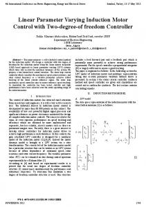
Figure 2 – Winding illustrative scheme for each primary package.
(34)
Active power transferred to the secondary through the airgap, referred to the space harmonic of order h are given by:
( ) ( Z&anh )
2 Pph = 3I aph ℜe Z& aph
(35)
2 Pnh = 3I anh ℜe
(36)
v vsxh = sx (37) h where vsx is the linear synchronous speed. The positive (Fuph) and negative (Fn) sequence and resulting (FR) propelling forces, are given by: Pph Fuph = (38) vsx
Funh = −
Pnh vsx
(39)
Fu = ∑ ( Fuph + Funh )
(40)
h
where vsx is the linear synchronous speed.
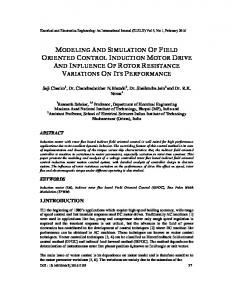
Specifications: (1) AC Power source/Analyzer; (2) Frequency: 45/1000 Hz; Voltage: 0 – 300V; Power: 4,5 KVA; Current Hall effect sensor; (3) Set of two blocks forming the stator; (4) Voltage Hall effect sensor; (5) Data acquisition board; (6) Microcomputer CPU; (7) Feeding from the mains. Figure 3 - Assembly diagram to obtain voltage and current waveforms.
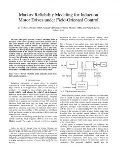
Figure 1 – Illustration of the linear induction motor used in all experiments (1) - aluminum linor; (2) – primary package.
The design for the primary packages has, finite length, open structure relatively to the magnetic circuit, when compared with the closed structure for the three-phase squirrelcage rotor induction motor, and the primary winding spread along the direction of movement. The mentioned factors, the solid secondary structure, and relative movement between primary and secondary are the elements responsible for the phenomena called border effects [4],[5],[6], and therefore for the unbalance between phase voltages and currents.
3 PROTOTYPE
4 EXPERIMENTAL TESTS AND RESULTS
Through the development of this work, was used a three-phase linear induction motor (LIM), two poles, short bilateral primary, built and tested in the laboratory. The primary packages (stator) with core made of silicon steel sheets, and the secondary (linor) built of a non-magnetic material, the aluminum, with a flat disc shape, as illustrated in Figure 1. The primary copper winding in each package is three-phase concentric, step series 1:8 and 2:7, single-layer, 200 turns/phase with the winding scheme presented in Figure 2.
In order to obtain the LIM parameters firstly the stator leakage inductances are obtained experimentally, the process is described in one of our previous works[1]. The primary phase resistances are obtained through direct measurements. Magnetization reactances are obtained at noload test, it corresponds to a condition without the linor or with the linor being driven at synchronous speed[3]. The secondary impedance determination is made with locked linor. In both cases the building of experimental procedures follows the scheme in Figure 3.
1 2
By applying to the machine a three-phase balanced sinusoidal voltage system, the data acquisition system will be registering the voltage and current waveforms referred to each test. The acquired voltage and current waveforms shows a high order time harmonic content. Therefore, through the use of Fast Fourier Transform (FFT) it is obtained the magnitude of harmonic content up to a certain specified order, in this work it is considered up to 50th harmonic, and it will be possible to estimate the Total Harmonic Distortion (THD) with a reasonable accuracy. Since it was observed that the voltage and current waveforms THD in time is less than 0.5% only the fundamental components in time are considered. Hence, it will be obtained the corresponding phasors to voltage and current waveforms. From the mathematical development shown at section 2, the parameters from the secondary will be found, considering harmonics up to the 11th order. 4.1 No load data Table 1 illustrate percent values related to the fundamental component from time harmonics content up to 7th order. Table 1 – Percent values related to the fundamental component, for harmonic content up to 7th order, from phase voltage and current waveforms. ------Va Vb Vc Ia Ib Ic Fund 100 100 100 100 100 100 2o 0.0701 0.0594 0.0958 0.0293 0.0126 0.0543 3o 0.1430 0.0505 0.0447 0.0599 0.0342 0.0278 4o 0.0324 0.0213 0.0296 0.0049 0.0034 0.0211 5o 0.0337 0.0229 0.0642 0.0094 0.0145 0.0185 6o 0.0590 0.0049 0.0446 0.0153 0.0032 0.0336 7o 0.0072 0.0166 0.0181 0.0255 0.0257 0.0113
Balanced voltage (V) from the source: VL = 77.0171 Resulting values (rms): Phase voltages (V): Va=46.9678; Vb=46.6967; Vc = 39.9741 Phase currents (A): Ia = 1.4900; Ib = 1.5297; Ic = 0.9897. 4.2 Locked linor data. Table 2 illustrate the percent values related to the fundamental component of time harmonic content up to 7th. Table 2. Percent harmonic content waveforms. ------Va Fund 100 2o 0.0616 3o 0.1680 o 4 0.0868 5o 0.1004 6o 0.1288 7o 0.0141
values related to the fundamental component, for up to 7th order, from phase voltage and current Vb 100 0.0240 0.1443 0.0424 0.0701 0.0407 0.0412
Vc 100 0.0470 0.0758 0.0535 0.1164 0.0779 0.0066
Ia 100 0.0589 0.1042 0.0458 0.0288 0.0467 0.0296
Ib 100 0.0285 0.0755 0.0244 0.0190 0.0201 0.0119
Ic 100 0.0332 0.0640 0.0279 0.0586 0.0431 0.0380
Balanced voltage (V) from the source: VL = 75.6990 Resulting values (rms): Phase voltages (V): Va=45,0288; Vb=45.3695; Vc = 40.7952 Phase currents (A): Ia = 3.2980; Ib = 3.2923; Ic = 2.5687.
Parameters obtained without taking in consideration the space harmonics are illustrated in Table 3 and in Table 4 are presented parameters referred to the fundamental space harmonic. Table 3. LIM parameters (Ohm), values obtained experimentally. Magnetization Impedances Reactance Phase Primary Secondary A 5.348+j5.729 11.608+j1.234 35.054 Table 4. LIM parameters (Ohm), values obtained experimentally referred to fundamental space harmonic. Impedances Magnetization Reactance Phase Primary Secondary A 5.348+j5.729 11.608+j1.232 34.736
5 THEORETICAL AND EXPERIMENTAL ANALYSIS. The theoretical and experimental validation is made through the comparison of measured and calculated values of currents and propelling forces. In the present investigation, it is verified the thrust characteristic as a function of linear speed, for different operating points. With this purpose, in the developed thrust measurement, was used a DC generator coupled to the axis of the secondary disk, with the generator feeding a resistive load bank. The speed measurements were made with an microprocessed encoder with an optical active sensor. Table 5. Speed (1-s) and corresponding measured (Iam), and calculated (Iac) currents and percent differences (Differ.%) related to measured currents at phase A. (1-s) Iam (A) Iac (A) Differ. % 0 2.7603 2.7491 0.4058 0.2133 2.5800 2.5705 0.3686 0.2770 2.5010 2.4914 0.3830 0.4256 2.3919 2.3867 0.2159 0.5486 2.2988 2.2290 3.0374 0.5913 2.2460 2.1956 2.2406 0.6167 2.2404 2.1975 1.9131 0.6383 2.2329 2.2326 0.0145 0.7108 2.2312 2.3218 -4.0605
The theoretical and experimental results are presented in Tables 5 to 7 and Figures 4 and 5. In those tables referred to currents are shown measured and calculated values and percent differences referred to measured values for a range of speed values (1-s), with s being the rotor slip. The percent deviation presented by current calculated values in the three phases, related to measured values, were not superior to 5%. This is the validation of the model applicability under the current point of view. Table 6. Speed (1-s) and corresponding measured (Iam), and calculated (Iac) currents and percent differences (Differ.%) related to measured currents at phase B. (1-s) Ibm (A) Ibc (A) Differ. % 0 2.7609 2.7397 0.7679 0.2133 2.5692 2.5484 0.8131 0.2770 2.4784 2.4596 0.7576 0.4256 2.3271 2.3262 0.0388 0.5486 2.1976 2.1404 2.6014 0.5913 2.1371 2.0952 1.9637 0.6167 2.1235 2.0885 1.6458 0.6383 2.1124 2.1142 -0.0861 0.7108 2.1009 2.1693 -3.2560
Table 7. Speed (1-s) and corresponding measured (Iam), and calculated (Iac) currents and percent differences (Differ.%) related to measured currents at phase C. 1-s Icm (A) Icc (A) Difer. % 0 2.1639 2.1441 0.9150 0.2133 1.9917 1.9854 0.3159 0.2770 1.9105 1.9086 0.0968 0.4256 1.7818 1.7744 0.4150 0.5486 1.6520 1.5980 3.2723 0.5913 1.5898 1.5505 2.4749 0.6167 1.5640 1.5371 1.7211 0.6383 1.5505 1.5484 0.1371 0.7108 1.4959 1.5618 -4.4053
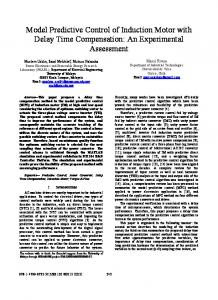
Charts in Figure 4 shows the behavior of measured and calculated values for parameters “b” and “c” as s function of (1s) where s is the rotor slip.
Tables 5 and 7 referred to currents, it is clear the small and perfectly acceptable percent difference between measured and calculated values. This makes the model applicable under the current point of view. The small deviation shown in Figure 7, when are considered the higher order space harmonics, also makes the model applicable under the propelling thrust point of view. The current unbalance in the Linear Induction Motor is caused not only by its design characteristic, but also due to the inherent border effects. Parameter determination for each phase of the LIM was made through the use of quantities that were measured from the machine’s terminals. The philosophy adopted in the development of this research was to implement new characteristics in our model. This first attempt, the inclusion of space harmonics show promising results. The follow up of this research is oriented through this path, and the next step will be the inclusion of other characteristics pursuing the minimization of differences between practical and theoretical results. 5 BIBLIOGRAPHY
Figure 4 – b e c against (1-s) where s is the slip. In Figure 6 stars and crosses show measured values (tests), and dotted and continuous lines indicate simulated values. Charts in Figure 5 shows the behavior of measured and calculated values of propelling force as a (1-s) function. In this figure the stars represents measured values (tests), and the continuous line is representing the calculated values considering space harmonics up to 11th. The dotted line refers to the situation where are considered the space harmonics.
Figure 5 - Thrust against (1-S) where s is the slip.
Charts in Figure 5 shows also that taking into consideration the propelling thrust in the range observed, deviations presented between measured and calculated values when considering the space harmonics are perfectly acceptable. However, when these harmonics are not considered the model can be applied only for no speed or near zero values for the speed. 4 CONCLUSION The idea of equivalence between the two machines is very promising, this will make easier future dynamic studies for the linear induction motor.
[1] L. MARTINS NETO and E. B. SANTOS, Method for the Determination of Inductances in a Linear Induction Motor, Proceedings of XII Brazilian Automatic Control Conference XII CBA, Brazil, September, 1998, vol. I, p. 231 – 236 (In portuguese). [2] W. D. STEVENSON JR., Elements of Power System Analysis, Fourth Edition, McGraw-Hill, New York, 1982. [3] J. F. GIERAS, Linear Induction Drivers, Clarendon Press, Oxford, 1994. [4] S. YAMAMURA, Theory of Linear Induction Motors, University of Tokio Press, Japan, 1978 . [5] I. BOLDEA I. and S. A. NASAR, Linear Motion Electromagnetic Systems , John Wiley & Sons, New York, 1985. [6] G. A. SIMONE, Double-Face Linear Asynchronous Converters – Theory and Design, Doctoral Thesis, FEE – UNICAMP, Campinas, SP, Brazil, 1992 (In portuguese). [7] L. MARTINS NETO; Asymmetrical Induction Motor as a Phase Number Converter, USP- São Paulo, Brasil, Doctoral Thesis, 1980 (In portuguese). [8] E. B. SANTOS, L. MARTINS NETO, J. R. CAMACHO, and R. S. T. PONTES, A Linear Induction Motor Parameter Determination Method, 5th Brazilian Power Electronics Conference – COBEP/99, Brazil, September, 1999, vol. 1, p. 265 - 268. [9] S. YAMAMURA et all, Theories of the Linear Induction Motor and Compensated Linear Induction Motor, IEEE Trans., 1972, PAS 91, p. 1700 – 1710. [10] S. YAMAMURA et all, Influence of End Effect on Characteristics of Linear Induction Motors, Jpn, Electr. Eng., 1971, 91, p. 136 – 147. [11] J. K. DUKOWICZ, Analysis of Linear Induction Motors with Discret Winding and Finite Iron Length, IEEE Trans., 1977, PAS-96, p. 66 – 73. [12] R. L. RUSSEL and K. H. NORSWORTH, Eddy Currents and Wall Losses in Screened-Rotor Induction Motors, Proc, IEE, 1958, 105 A, p 163 – 175. [13] H. Bolton, Transverse Edge Effect in Sheet-rotor Induction Motors, Proc. IEE, vol. 116 n. 5, 1969, p. 725 – 731. [14] E.B. DOS SANTOS, L.M. NETO and J.R. CAMACHO, Linear Induction Motor Parameter Determination on Force Development Applications; Proceedings of the IEEE - PES Winter Meeting 2000 - Singapore, January, 23 - 27, 2000.