Aug 10, 2005 - Power is now a major problem even for high end microprocessors. Intel canceled the next generation Tejas Pentium 4 chips due to.
Linear Programming for Sizing, Vth and Vdd Assignment D. G. Chinnery and K. Keutzer
Department of Electrical Engineering and Computer Sciences University of California at Berkeley
{chinnery,keutzer}@eecs.berkeley.edu ABSTRACT
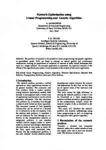
AND2 cell choices:
Most circuit sizing tools calculate the tradeoff between each gate’s ∆P AND2X1 – delay 2ns, power 1mW − = 1mW /1ns delay and power or area, and then greedily change the gate with the AND2X2 – delay 1ns, power 2mW ∆d best tradeoff. We show this is suboptimal. Instead we use a linear AND4 cell choices: program to minimize circuit power. The linear program provides a AND4X1 – delay 2ns, power 2mW − ∆P = 2mW /1ns fast and simultaneous analysis of how each gate affects gates it has ∆d AND4X2 – delay 1ns, power 4mW a path to. Our approach reduces power by up to 30% compared to Figure 1. Greedily choosing the gate with the maximum sensitivity commercial software, with a 0.13um library. The runtime for posing is suboptimal: If all the gates are initially size X2, the critical path is and solving the linear program scales linearly with circuit size. 2ns and power is 12mW. Consider a 3ns delay target. The max power_reduction/delay_increase sensitivity approach results in Categories and Subject Descriptors sizing down the AND4 gate, giving total power of 10mW. If the B.6.3 [Logic Design]: Design Aids – optimization. four AND2 gates are sized down instead, the power is only 8mW. General Terms: algorithms, design, performance. u w v Keywords: delay, linear program, power, sizing. a x z b 1. INTRODUCTION Gate sizing algorithms have changed little in the past 20 years. In Figure 2. A circuit for illustrating the delay constraints. 1985, Fishburn and Dunlop proposed a fast method to minimize An alternative linear programming approach to minimize the power area and meet delay constraints, greedily picking the transistor with of a combinational circuit is as follows [7], in our terminology: maximum delay_reduction/transistor_width_increase at each step [2]. Variants of this are still standard in commercial sizing tools. ⎛ ⎞ min ⎜ γ v ∆Pv ⎟ (1) Power is now a major problem even for high end microprocessors. v∈V ⎝ ⎠ Intel canceled the next generation Tejas Pentium 4 chips due to power consumption issues. Reducing power extends battery life, With delay constraints of the form (as illustrated in Figure 2), and reduces heat dissipation and packaging costs. The same sizing Tmax ≥ tvw ≥ tuv + d v + γ v ∆d v (2) approach is used to minimize power. Srivastava et al. used max delay_reduction/power_increase to meet delay constraints, after 0 ≤ γv ≤1 (3) reducing power by assigning gates to low supply voltage (Vdd) [8]. where ∆Pv0 is the delay increase Greedy heuristics that pick the gate with the maximum sensitivity if gate v’s cell is changed. t is the arrival time at gate v from gate uv fail to consider the whole circuit and are suboptimal (e.g. see Figure u; d is the delay of gate v; t is the arrival time at gate w from gate v vw 1). The challenge is to find a better approach with fast runtimes. v; and Tmax is the maximum delay allowed. Cell choice variable Several groups have used convex optimization, requiring convex γv∈[0,1] determines if a cell is changed to a functionally equivalent models, to find a globally optimal solution. In our experience, linear cell (γ = 1 if it is used, γ = 0 if not, but γ may be inbetween 0 and 1). models are inaccurate – least squares fits vs. gate size to 0.13um The cell alternative for gate v with minimum ∆Pv/∆dv is used in the library data had delay inaccuracy of 20%. Linear program (LP) LP formulation. Given γv from the LP solution, the cell that solvers with linear models can scale to problems with millions of minimizes gate v’s power with delay less than dv + γv∆dv is chosen. variables. Higher order convex models, such as posynomials [4], are The delay models in [7] were inaccurate due to ignoring slew and at best accurate to within 5% to 10% [4][9], because real data for wire loads, and only considering the worst timing arc through a gate delay and power is not a convex function of gate size – e.g. due to to determine d and ∆d . As the fanin delay impact due to changed v v transistor folding for layout of larger cells. Sacrificing delay input capacitance C was not modeled, gates could not be upsized in accuracy is unacceptable, when a 10% delay increase can give 20% to avoid increasing fanin delay. There was no method for reducing power savings (e.g. compare power at 1.1Tmin and 1.2Tmin in Table delay, so [7] required starting at minimum delay. We tested this 2). Posynomials require geometric program solvers with runtimes approach on a 17,000 gate inverse discrete cosine transform block – that scale cubically [4], so optimizing circuits of more than several the simplistic models resulted in a 24% increase in the clock period hundred gates is computationally infeasible. when measured in Synopsys Design Compiler, despite a tight delay constraint. Also, the leakage in [7] is overstated for 0.18um, 59% of total power, which exaggerates the power reduction with multiple Permission to make digital or hard copies of all or part of this work for threshold voltages. The approach in [7] does not handle multi-Vdd personal or classroom use is granted without fee provided that copies are assignment in the LP. Instead integer linear programming was used not made or distributed for profit or commercial advantage and that for multi-Vdd assignment, which scales poorly with circuit size. copies bear this notice and the full citation on the first page. To copy otherwise, or republish, to post on servers or to redistribute to lists, We pose the linear program in a similar manner to [7], but model requires prior specific permission and/or a fee. each timing arc, and include wire loads. We model the impact of ISLPED’05, August 8–10, 2005, San Diego, California, USA. slew on delay of fanouts, and the impact of Cin changing on fanin Copyright 2005 ACM 1-59593-137-6/05/0008...$5.00. delays. This increases the accuracy of delay constraints. In an outer
∑
2. LINEAR PROGRAM FORMULATION 2.1 Gate modeling in the linear program As outlined earlier, a central optimization issue is the accuracy of the delay and power models. The linear program constraints must model the impact on delay and power due to changing gate size, Vdd, or Vth. Consider changing a single gate’s cell. Cin of the gate’s input pins loads the fanin gates, affecting their delay and switching power. The gate’s drive strength affects its delay and output slew, which may increase the delay of paths the gate is on, and the internal power of fanouts may be affected by the change in output slew. If the gate’s voltage changes, that affects the switching power for the load it drives (0.5fCloadVdd2, where Cload is the load capacitance, and f is the switching frequency of the output). The gate leakage increases exponentially with decreasing Vth. The gate size primarily determines Cin. Size (transistor width), Vdd, and Vth all affect the gate drive strength. We examined the impact of changing a gate on its power and delay, and the power and delay of neighboring gates. More than 95% of the change in power can be calculated at that gate: switching power due to Cin; switching power of the load with Vdd; leakage power; and internal power. Slew changes affect the short circuit power of neighboring gates, but that is only a small part of the total power (typically less than 10%). Thus to determine the change in power by changing a gate, we only need to consider the gate itself and can avoid computing the impact on other gates. This avoids unnecessary computation, while still being accurate. In contrast, changing Cin and output slew significantly impacts the delay of neighboring gates. The impact of Cin is limited to the immediate fanins (the fanins of fanin gates do not see the change in load capacitance – static CMOS logic decouples this). However, the delay and slew changes of fanins and of the gate itself propagate
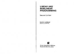
vdd 1.2V, vth 0.08V
15 Power (uW)
loop around LP iterations, we perform static timing and power analysis to ensure accuracy (which is exact vs. Design Compiler). ∆dv