Copyright IPCO-2014 Vol.2 ISSN : 2356-5608
Linearizing control input-output of a wind turbine permanent magnet synchronous #1
Riad AISSOU , Toufik REKIOUA 1,2
#2
Laboratory of Industrial Technology and the Information « LT2I »,
Faculty of Technology, University A. Mira, Targa Ouzemour, Bejaia, Algeria 1
[email protected]
Abstract — In this paper, we study the control voltage at the output of a permanent magnet synchronous generator (PMSG) connected to a PWM rectifier. The input-output linearizing control is tested for PMSG. This device is intended for an application of wind energy conversion in the case of an isolated site. The results of the different simulations of the entire chain conversion performed under MATLAB / Simulink, were used to evaluate the performance of the proposed system. Keywords— Linearizing control input-output; wind turbine; permanent magnet synchronous generator (PMSG); PWM Rectifier;
I. INTRODUCTION The power generation sector is the largest consumer of primary energy and two-thirds of its sources are fossil fuels. It is technically and economically capable of making significant efforts to reduce violations of human activity on climate and the environment. One possibility is to increase the rate of production of electricity from resources of non-renewable fossil type and Today, renewable generation sources, including solar and wind energy, which are the growth rate is highest. The wind power generator, which is based on a variable speed turbine and a synchronous permanent magnet generator is connected to a DC bus through a PWM power converter. [1] However, stand-alone operation, the rotational speed and the load is not fixed, the stator voltage can vary within wide limits. It then becomes necessary to use an appropriate control system to maintain the output voltage at a constant amplitude and frequency. The input-output linearizing command is a command which generalizes the vector-ensuring decoupling and linearization of the relationship between inputs and outputs. Assuming that all of the state vector is measurable, it is possible to design a nonlinear state feedback which ensures the stability of the closed loop system [2]. This article focuses on the application of the input-output linearizing the wind energy conversion system control with a variable rate based on a permanent magnet synchronous
2
[email protected]
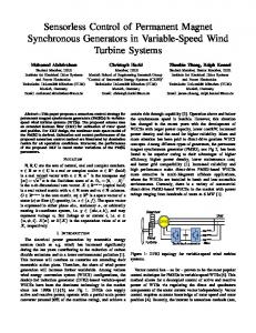
generator. The overall plan of studies of the system is represented by the figure 1. Results of the simulation of the dynamic behavior of the studied system are presented. From these results, we can verify the effectiveness and reliability of the applied control. II.
MODELING OF WIND GENERATOR
The wind power generator, comprising a variable speed turbine coupled directly to a PMSG connected to a DC bus through a PWM power converter, is shown in Figure 1
Fig. 1. Schematic diagram of the system studied.
II.1 MODEL TURBINE The power of the air mass that passes through the surface of the turbine S is given by [3,4]: p ρs V (1) With s : The effective area through which the wind, ρ : The density of the air (1.25kg / m3), V : The wind speed, We focus our work in the operation of a vertical axis turbine. The value of the active surface (S) was replaced by the geometric dimensions of the wing shown in Figure 2 where:
S=2*R*H S (2) W With H : height of the t turbine. R : The radiuss of the turbinee.
J
J
C
C
f
Ω
f
(88)
wh here : J et J : are thhe inertias of tthe turbine an nd of the machhine respeectively, f et f : the cooefficient of frriction of the engine and off the bladees respectivelyy, C : the staatic torque proovided by the wind. In n our applicatiion, we consider that the friction f associiated with the generatoor (one the wing will no ot be taken into accou unt), then: C C J f Ω (9) II.. 3 MODEL OF O THE SYNC CHRONOUS MACHINE
Fig. 2. Geometric Dimensioning Savoonius wing
For describingg the operatinng speed of a wind turbine, the F low w s speed (specificc) λ is used, where w : R.Ω λ (3)
Th he equations for f the PMSG G, can be writtten in a refereence linkeed to the rotor as follows: [77] V V
V
R : The radiuss of the wind turbine t blades, Ω : The angulaar speed of rotation of the blades, b V : Wind speed.. s W Wind power and a power exttracted by thee wind p be expressed e in terms t of the poower coefficieent c
can
P Cp pP (4)) The power cooefficient Cp is often derivved from praactical T meaasures: 0.21 (5) c λ 121 λ 0.0856 λ 0 0.2539 λ Figuure 3 shows thhe power coeffficient Cp
R I
R I L
L I
I
pω L
pω L I
I pω
(10))
with w : R : Resistance of the stator w windings. I , I : Currennts in the statorr mark Park. V , V : Statorr voltages in thhe benchmark k Park. L , L : Inducttions in the staator cyclical mark m park. p : Number of pole p pairs. ω : The pulse voltages v (rad/ss). : The flux crreated by the permanent magnet throughh the stator windings. • Expressionn of the power and electrom magnetic torquee Th he expression of electromaagnetic torquee in the reposiitory Park C
P L
L
I I
I
(11)
II..4 Modeling Rectifier R Modeling M of thhe rectifier iss made by a set of switcches idealls. These sw witches are ccomplementarry, their statee is defin ned by the folllowing functioon [8, 9]: of thee blade Savonius type t studied
Fig. 3. Cuurve
F From this pow wer, the wind torque t is givenn by: P
C
(6)
B replacing the By t value of thhe power by the t product (ttorque * sppeed) C
C
R
H V
(77)
I II.2 MODELIING OF THE SHAFT OF THE T MACHIN NE T differential equation thhat characterizzes the mechaanical The behhavior of the tuurbine and gennerator is giveen by [6].
Fig. 4. Schema of association PMSG-PWM rectifier
1, s 1, s
s
I I
X
f x y
for s=a ,b ,c
The input voltage and the output current phase can be written in terms of: Sj, and Vdc input currents ia, ib, ic. i i 0 (12) i
with :
Input voltages between phases of the PWM rectifier can be described by:
x x x
S S S
U U U
S U S U S U
y t
X
(13)
U
.U
U
.U
U
.U
(15)
Finally, we deduce the equation coupling between AC and DC sides by: c
U
s i
s i
si
i
(16)
The previous equations in synchronous dq coordinates are: e Ri L ωLi U (17) Ri
e c
U
L s i
ωLi s i
U
(18)
i
(19)
h x h x
I I V
V V
R
a
(20)
y t y t
;U
L
b
L
;a
E C
V I L
;G x
0
; 0 L
0
0 a x a x b x b x b c c R
;b
L
;c
L
x x
f x f x f x
0 g 0 g ;f x 0 0 where :
The equations for the voltage phase balanced system without neutral connection can be written as: e U i i e U R i L i (14) e i i U with :
G x .U t H x
L IL
;c
C
L
;b
L
;
.
The linearization condition to check if a nonlinear system admits a linearization input - output is the order of the relative degree of the system. The following notation is used for the Lie derivative of the function h x along a vector field f x f x … f x [11]. Lh
∑
f x
¾
Lh
L L
h
¾
L Lh
¾
L X
X
f x (21)
G x .
¾ degree relative The relative degree of output is the number of times that is needed to derive the output to bring up the input U. The future output y(t+ τ) is calculated by: • Relative degree of the rectified voltage . (22) .
with :
(23)
with : s s
√
√
2s s
s
s . cos ωt
s . cos ωt
√
√
2s
s
s . sin ωt 0
s
s . sin ωt 0
III.
APPLICATION OF THE LINEARIZING CONTROL INPUT OUTPUT FOR PMSG Our command is to control the stator current I and the rectified voltage V of PMSG. For this we chose as the state vector x I I V T , and as output y= V I T and control vector u V V T. The model of PMSG, expressed in the rotor reference frame related to the form of equation of state:
Relative degree of
• y t With :
is
2
Relative degree of the current h x
Lh x
L h x .U
(24)
L h
g
0
0
(32)
0
The matrix defining the relationship between the physical IV. SIMULATION RESULTS inputs (U) and the derivatives of the outputs (y (x)) is given by the following expression : Full operation of the device was simulated in the Matlab Simulink . In this control strategy, the reference voltage at the (25) output of the rectifier is taken equal to Vdc−ref = 40 V and the variation of the wind speed is shown in Figure 5. In what follows, we present simulation results. With : 15
14.5
0 0 To linearize the input-output behavior of the generator in a closed loop non-linear state feedback is applied according to [24]
Vitesse du vent en (m/sec)
14
13.5
13
12.5
12
11.5
11
V V
D
x
A x
V V
0
2
4
(26)
6
8
10 temps en sec
12
14
16
18
20
14
16
18
20
14
16
18
20
Fig. 5. Wind speed 45
The determinant of the matrix decoupling D (x) is not null
40
0
x
35
(27)
0
Vdc Vdcref
30 Vdc en (V)
D
(28)
25 20 15 10 5
Substituting (27), (28) into (26) we have:
0
0
2
4
6
8
10 temps en sec
12
Fig. 6. Rectified voltage 6
Entries V V I et V I e
K e
K
e
V
I
K
V
K e
V
K
0
I
I V
V
(29)
are defined as follows:
V
Internal inputs V
V
0
K
0
3
2
0
V
V
(30)
(31)
The coefficients (K , K , K ) are selected so that equation (30) is a polynomial HURWITZ [11].
4
1
I V
Id Idref
5
Id en (A)
e
are calculated by imposing a static regime V and the dynamic error.
-1
0
2
4
6
8
10 temps en sec
12
Fig. 7. Direct current
Wind speed show in Figure 8 is modeled as a sum of deterministic several harmonics [11] : V t 10 0.2 sin 0.1047 t 2 sin 0.2665 t sin 1.2930 t 0.2sin 3.6645 t [36]
different simulations were discussed and validated mathematical models of the system proposed wind.
14
13
Vitesse du vent en (m/sec)
12
11
ANNEXES 10
9
8
7
0
2
4
6
8
10 temps en sec
12
14
16
18
Désignation
Valeur
nominal voltage
Vn = 90 V
nominal current
In= 4.8 A
nominal power
Pn= 600 W
Number of pole pairs
2 p = 17
Winding resistance
Rs = 1,137 Ω
synchronous inductance
Ls = 2.7 mH
efficient flow
Φeff = 0.15 Wb
Coefficient of friction
f = 0,06 N.m.s/rad
Inertia of the GSAP
J = 0.1 N.m
Radius of the wing
R = 0.5 m
Height of the wing
H=2m
active surface
S = 2 m2
Inertia of the wing
J = 16 kg.m2
20
Fig. 8. Wind speed 45 40 35 Vdc Vdcref
Vdc en (V)
30 25 20 15 10 5 0
0
2
4
6
8
10 temps en sec
12
14
16
18
20
Fig. 9. Rectified voltage 6 Id Idref 5
Courant Id en (A)
4
3
2
1
0
-1
Density of air 0
2
4
6
8
10 temps en sec
12
14
16
18
ρ
1.2 kg/m
20
Fig. 10. Direct current
The response of the voltage at the output of the rectifier is given in Figures 6, 9. We can see that the voltage is well regulated. This is also the case of the current Id and the rejection of disturbances made in this case by changes in wind speed is ensured. V. CONCLUSION In this article, we presented the study of voltage control system consists of a permanent magnet synchronous generator feeding a PWM rectifier. The proposed control strategy is based on the input-output linearizing control to ensure good performance. Law control system has been detailed. The results of
REFERENCES [1] D. Seyoum and C. Grantham, ‘Terminal Voltage of a Wind Turbine Driven Isolated Induction Generator Using Stator Oriented Field Control’, Transaction on Industry Applications, pp.846–852, 2003. [02] R. HEDJAR, R. TOUMI, P. BOUCHER, D. DUMUR, "Cascaded Nonlinear Predictive Control of Induction Motor", European Journal of Control, Vol.10, Nb.1. [3] B. Multon, X. Rehoboam B. Dakyo, C. Nichita, O. Gergaud and H. Ben Ahmed, 'Wind turbine Electrical', Technical Engineer, Treaties of Electrical Engineering, D3960, November 2004. [4] O. Gergaud 'Energy Modelling and Economic Optimization of Production System and Wind Power Photovoltaic Grid Network Associate and a
battery', PhD thesis, Eole Normale Superieure de Cachan, December 2002. [5] S. Belakehal * A. Bentounsi, M. and H. Merzoug Benalla 'Modelling and control of a permanent magnet synchronous generator dedicated to the conversion of wind energy' Journal of Renewable Energy Vol. 13 No. 1 (2010) 149-161. [6] R. Cardenas-Dobson, ‘Control of Wind Turbine Using a Switched Reluctance Generator’, PhD Thesis, University of Nottingham, 1996. [7] F. Khatounian "Contribution to the Modeling, The Identification and Control of a Haptic Interface for a Degree of Freedom Driven by a Permanent Magnet Synchronous Machine" PhD thesis, normal upper school, Cachan, France, 2006.
[8] AS Toledo, 'Direct Observation and Control Power Converter: Application to the three-phase voltage inverter', PhD thesis, Graduate School of the National Polytechnic Institute, Grenoble, 2000. [9] Communication, 'Synchronous Motors and Industrial Applications' Days of Education, Electrical Engineering and Industrial Electronics, SEEMAFPEN, Gif-sur-Yvette, March 1995. [10] R.ERROUISSI. "Contribution to the nonlinear predictive control of a permanent magnet synchronous machine." Ph.D. Thesis, University of Chicoutimi QUEBEC, June 2010. [11] Rachid Errouissi, Mohand Ouhrouche. « Nonlinear Predictive controller for a permanent magnet synchronous Motor drive » university of Quebec at Chicoutimi