SANDIA REPORT SAND2004-5670 Unlimited Release Printed December 2004
Lipid Membranes on Nanostructured Silicon
Darryl Y. Sasaki, Gabriel P. Lopez, S.R.J. Brueck, Reema R. Zeindeldin, Julie A. Last, Andrea L. Slade, Paul Bisong, Michael J. O’Brien, Linnea K. Ista Prepared by Sandia National Laboratories Albuquerque, New Mexico 87185 and Livermore, California 94550
Sandia is a multiprogram laboratory operated by Sandia Corporation, a Lockheed Martin Company, for the United States Department of Energy’s National Nuclear Security Administration under Contract DE-AC04-94AL85000.
Approved for public release; further dissemination unlimited.
1
Issued by Sandia National Laboratories, operated for the United States Department of Energy by Sandia Corporation. NOTICE:
This report was prepared as an account of work sponsored by an agency of the United States Government. Neither the United States Government, nor any agency thereof, nor any of their employees, nor any of their contractors, subcontractors, or their employees, make any warranty, express or implied, or assume any legal liability or responsibility for the accuracy, completeness, or usefulness of any information, apparatus, product, or process disclosed, or represent that its use would not infringe privately owned rights. Reference herein to any specific commercial product, process, or service by trade name, trademark, manufacturer, or otherwise, does not necessarily constitute or imply its endorsement, recommendation, or favoring by the United States Government, any agency thereof, or any of their contractors or subcontractors. The views and opinions expressed herein do not necessarily state or reflect those of the United States Government, any agency thereof, or any of their contractors. Printed in the United States of America. This report has been reproduced directly from the best available copy. Available to DOE and DOE contractors from U.S. Department of Energy Office of Scientific and Technical Information P.O. Box 62 Oak Ridge, TN 37831 Telephone: (865)576-8401 Facsimile: (865)576-5728 E-Mail:
[email protected] Online ordering: http://www.osti.gov/bridge
Available to the public from U.S. Department of Commerce National Technical Information Service 5285 Port Royal Rd Springfield, VA 22161 Telephone: (800)553-6847 Facsimile: (703)605-6900 E-Mail:
[email protected] Online order: http://www.ntis.gov/help/ordermethods.asp?loc=7-4-0#online
2
SAND 2004-5670 Unlimited Release Printed December 2004
Lipid Membranes on Nanostructured Silicon Darryl Y. Sasaki, Julie A. Last, and Andrea L. Slade Biomolecular Materials and Interfaces Department Sandia National Laboratories Albuquerque, New Mexico, 87185-1413 Gabriel P. Lopez, Reema R. Zeineldin, Paul Bisong, Michael J. O’Brien, Linnea K. Ista Department of Chemical and Nuclear Engineering University of New Mexico Albuquerque, New Mexico 87131 S. R. J. Brueck Center for High Technology Materials University of New Mexico Albuquerque, New Mexico 87106
3
Abstract A unique composite nanoscale architecture that combines the self-organization and molecular dynamics of lipid membranes with a corrugated nanotextured silicon wafer was prepared and characterized with fluorescence microscopy and scanning probe microscopy. The goal of this project was to understand how such structures can be assembled for supported membrane research and how the interfacial interactions between the solid substrate and the soft, self-assembled material create unique physical and mechanical behavior through the confinement of phases in the membrane. The nanometer scale structure of the silicon wafer was produced through interference lithography followed by anisotropic wet etching. For the present study, a line pattern with 100 nm line widths, 200 nm depth and a pitch of 360 nm pitch was fabricated. Lipid membranes were successfully adsorbed on the structured silicon surface via membrane fusion techniques. The surface topology of the bilayer-Si structure was imaged using in situ tapping mode atomic force microscopy (AFM). The membrane was observed to drape over the silicon structure producing an undulated topology with amplitude of 40 nm that matched the 360 nm pitch of the silicon structure. Fluorescence recovery after photobleaching (FRAP) experiments found that on the microscale those same structures exhibit anisotropic lipid mobility that was coincident with the silicon substructure. The results showed that while the lipid membrane maintains much of its self-assembled structure in the composite architecture, the silicon substructure indeed influences the dynamics of the molecular motion within the membrane.
4
Contents Abstract ……………………………………………………………………………… Acknowledgment …………………………………………………………………… Introduction ………………………………………………………………………… Results and Discussion …………………………………………………………… Nanostructured silicon wafer …………………………………………………… Supported lipid bilayers on planar and nanostructure silicon – fluorescence microscopy ………………………………………………… Supported lipid bilayers on planar and nanostructure silicon – AFM imaging …………………………………………………………… Conclusion ………………………………………………………………………… Experimental ……………………………………………………………………… References …………………………………………………………………………
3 5 7 9 9 11 17 21 21 24
Figures 1 2 3 4 5 6 7 8 9 10 11 12 13
FE-SEM of etched nanostructured silicon wafer ……………………………… Confocal microscopy images of egg-PC bilayers on planar and nanostructure silicon ………………………………………………………… FRAP of bilayers on planar silicon …………………………………………… FRAP of bilayers on nanostructured silicon …………………………………… Background subtracted images of FRAP studies from Fig. 4 ………………… Schematic representation of bicelle …………………………………………… Confocal microscopy images of DHPC/DPPC bilayers on planar and structured surfaces …………………………………………………………… Confocal microscopy images of DHPC/DPPC bilayers after photobleaching ………………………………………………………………… AFM images of DHPC/DPPC bilayers on planar silicon ……………………… AFM images of nanostructure silicon before and after fusion with DHPC/DPPC bilayers ………………………………………………………… Height profiles of nanostructure silicon before and after fusion with DHPC/DPPC bilayers ………………………………………………………… Schematic of nanocomposite architecture …………………………………… High resolution image of DHPC/DPPC bilayer on nanostructured silicon ……
5
11 11 12 13 14 14 15 16 17 18 19 19 20
Introduction
Supported lipid bilayers have garnered a large body of interest from researchers in areas as dispersed as cellular membrane function to drug discovery. A major driving force in this area is the movement toward the isolation and study of cellular membrane proteins. Membrane proteins include a vast array of structure types that vary widely in function, including ion channels, motor proteins, cell adhesion proteins, and the T cell receptors and major histocompatibility complex that form the immunological synapse. i The major issue in dealing with these membrane proteins is that they require a proper lipid membrane environment, which includes correct lipid phase and functionality, for correct folded structure and function. A number of different membrane forms can be used to capture and study the proteins as well as utilize them in applications, such as sensing ii, iii , iv and drug testing. v The most common form is the spherical lipid vesicle, also known as the liposome. vi Another form that is in common use today is the bicelle, which is a disk-like membrane structure composed of long and short chain lipids. vii The ability to transfer these solution phase membrane structures to a solid surface allows a number of characterization techniques to be used and device structures to be realized. These supported lipid bilayers (SLB) viii can be prepared either on a flat, solid surface or suspended across a hole through a variety of techniques (e.g. vesicle fusion ix ). In the latter case, the hole spanning membrane is called a black lipid membrane (BLM) and is generally limited to use in an electrochemical cell for the study of ion channels and protein-membrane interactions. x The former case has associated with it a number of varied architectures and device applications. Novel substructure architectures for supported lipid membranes have arisen mainly as means to restore molecular mobility in the membrane that can become inhibited when adjacent to solid surfaces. On solid hydrophilic surfaces, such as silicon, supported lipid bilayers typically rest upon a thin cushion of water of thickness between 0.5 – 1 nm. xi By increasing the hydration layer between the substrate and the membrane, molecular mobility can be recovered. One useful method is the insertion of hydrogels, such as polymethacrylic acid, xii polyethylene glycol, xiii, xiv and polyelectrolytes, xv between the membrane and substrate. The hydrogel provides a water-like support to the membrane, but it too is not completely void of interference with the membrane’s molecular mobility. xvi Tethering with long chain molecules has also been successfully employed to increase the separation between the membrane and the substrate. xvii,xviii 6
Bacteriorhodopsin, xix bacterial surface layer proteins (S-layer proteins) xx , and multi-bilayers xxi can also be used as spacers to improve lipid mobility in the supported membrane. Although these constructs can support lipid membranes and maintain membrane protein function, the ability to exchange solutions on the supported side of the membrane, and do so in a compartmentalized fashion, is not currently feasible. Nanoscale patterning of silicon wafers has recently been developed by Brueck et al. to generate a variety of structures over a large area with good uniformity. xxii, xxiii , xxiv The patterning technique used is called laser interferometric lithography, which uses an optical interference pattern to develop a photolithographic mask. The silicon structure is then prepared using anisotropic wet etching followed by thermal oxidation. The approach has most recently been used to prepare a nanofluidic structure that uses electrophoresis for fluid transport. xxv Configuring such a patterned structured material with a supported lipid bilayer could offer (1) a suspended lipid membrane that is separated tens to hundreds of nanometers from the underlying substrate thereby eliminating substrate interfacial interactions, (2) conferring an innate nanofluidic architecture for potential biosensor/bioseparations applications, and (3) a novel nanocomposite material with its own unique physical and mechanical characteristics that may yield new insights on asymmetric molecular dynamics in self-organized materials. The goal of this project was to generate a composite material composed of molecularly dynamic lipid membranes with the nanostructured silicon described above in an effort to develop a new materials architecture that could be applied towards membrane protein studies, biosensor systems, and biocompatible nanofluidics. This unique composite also provides a route into understanding how interfacial interactions and structures dictate physical and mechanical behavior through the confinement of phases and/or lipid and protein assemblies in the membrane. We have accomplished the successful fusion and detection of mono- and bi-phasic lipid membranes on the nanostructured silicon surface using both fluorescence microscopy and in situ tapping mode AFM. In this work the membranes were found to span the ridges of the structure creating an undulated topology, much like how a canvas canopy drapes over a trellis. Fluorescence recovery after photobleaching (FRAP) experiments found that on the microscale those same structures exhibit anisotropic lipid mobility that was coincident with the silicon substructure. The results showed that while the lipid membrane maintains much of its self-
7
assembled structure in the composite architecture, the silicon substructure indeed influences the dynamics of the molecular motion within the membrane.
Results and Discussion Nanostructured silicon wafer Nanolithographically defined silicon wafers in stripes or post patterns with a pitch of ~500 nm were prepared according to O’Brien and coworkers (2003). We have based our fabrication efforts on optical lithography, which is well developed, reliable, and flexible. Interferometric lithography (IL), a maskless technique based on the interference of two or more coherent beams, allows one to inexpensively and quickly pattern nanoscopic features over large surface areas with easily varied feature dimensions (e.g., pitch size and channel width). With IL two coherent light beams of wavelength λ are crossed at an angle 2θ, producing a regular interference pattern with d = λ/(2×sinθ) describing the period. With an ultraviolet light source, one can easily obtain periods on the order of hundreds of nanometers and transverse pattern features in the sub-100 nm range, well beyond the scales available from traditional optical lithography approaches. Developments such as deeper ultraviolet sources and immersion techniques promise to reduce these scales to sub-100 nm periods and ~10 nm channel widths. A principal advantage of this nanopatterning method over more conventional methods (e.g. e-beam lithography) is the ease by which macroscopic patterned areas can be created. Silicon wafers were cleaved into 3 cm × 4 cm chips, cleaned in piranha solution (1 part H2O2, 2 parts H2SO4 by volume), triple-rinsed with deionized (DI) water, dipped in HF acid (to remove the native oxide layer and any remaining inorganic contaminants), and again triplerinsed with DI water. A 150 nm thick layer of XHRiC-16 (Brewer Science, Inc.) anti-reflective coating (ARC) was spin-deposited (4000 rpm, 30 sec) and hard baked at 175 °C for 3 min. This was followed by spin-deposition (4000 rpm, 30 sec) of a 200 nm layer of positive photoresist [SPR510a photoresist diluted by an equal amount of EC-11 solvent (Shipley, Inc.)] and softbaking at 95 °C for 3 min. The exposure source was the frequency-tripled (λ = 355 nm) output of a YAG-Nd laser (Infinity 40-100, Coherent Inc.). The laser beam is expanded and illuminates a right-angle assembly containing a mirror and a vacuum chuck to hold the Si sample. Although
8
we have focused on pitches of 500 nm (θ ~26°), the reflector assembly can be rotated to produce a variety of grating pitches. After exposure, each sample was soft-baked at 110 °C for 1 min., developed using undiluted MF702 developer (Shipley, Inc.) and rinsed with water, leaving a photoresist grating. The developed chip was placed in an e-beam evaporator where a thin (35 to 40 nm) layer of Cr was deposited. The remaining photoresist (and the Cr on top of it) was then lifted off using an airbrush acetone spray, leaving a negative-tone Cr etch mask layer on top of the remaining ARC (which is impervious to the acetone). Once the etch masks are completed, the chips are placed within a parallel-plate reactive ion etcher (RIE). Within such a device, the samples sit on the lower plate while the upper plate has numerous holes to deliver etchant gases into the chamber. At low (few mTorr) pressures, RF oscillatory potentials are applied between the plates. These electric fields ionize the normally inert etchant gases, liberating the molecular radicals that will etch the substrates. Once ionized, the (relatively) straight electric field lines between the capacitor plates will drive the (charged) ions anisotropically towards the substrates. An etch process was used that employs CHF3 and O2 gases. The mechanism behind these gas interactions with respect to etching is well known. Once ionized, CHF3 molecules supply the needed fluorine radicals to etch silicon. However, the radicals from the CHF3 molecules also recombine into a hydrocarbon polymer that deposits itself on the sample, providing a shield against further etching. This shielding phenomenon is known as "passivation." Ionized oxygen radicals, however, will burn up this hydrocarbon polymer. Because the oxygen radicals are driven along the straight electric field lines between the capacitor plates, they can be used to burn up the polymer at the horizontal surfaces of the sample at a rate faster than it is deposited, while leaving the vertical sidewalls passivated. This sidewallpassivation scheme yields superior etch anisotropy and is achieved by finding a "recipe" of etch parameters (pressure, RF power, gas flow parameters) for each individual RIE unit by trial-anderror. After etching, the samples are exposed to pure oxygen plasma to burn away the remaining polymer. Subsequent immersion in piranha solution disintegrates residual organics.
9
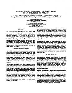
A field-emission scanning-electron microscope (FE-SEM) image of etched silicon wafer before and after oxidation is shown in Figure 1.
(A)
(B)
Figure 1. FE-SEM images of etched samples: (A) silicon wafer after etching, and (B) the same wafer after oxidation. All samples have been sputtered with gold prior to imaging to reduce charging effects. The scale bars indicate distances of 100 nm.
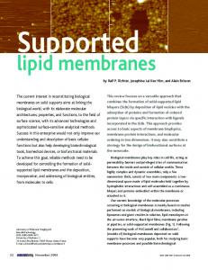
Supported lipid bilayers on planar and nanostructured silicon – fluorescence microscopy For the fluorescence microscopy studies both vesicular and bicelle structures were used to generate the membrane-fused materials. The vesicular structures were prepared by extrusion or sonication using egg-phosphatidyl choline (egg-PC) doped with 0.5% of fluorescent-labeled phosphatidylethanolamine (PE) lipid. Fusion of the lipid bilayers on the substrates was accomplished by simply incubating the lipid vesicles with either the oxidized planar or nanostructured silicon. Homogeneous lipid bilayer films were successfully prepared on both surfaces as evidenced by the homogeneous fluorescence covering the substrates (Figure 2).
A
B
10
Figure 2. Confocal microscopy image of lipid bilayers formed on either (A) planar silicon or (B) nanostructured surfaces using single unilamellar vesicles made of 0.5 mol% fluorescent lipid (rhodamine labeled) within an egg-PC membrane. (Image sizes are (A) 900 µm, and (B) 1.8 mm).
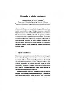
The FRAP experiments consisted of photobleaching a small area of the bilayer with intense light over a short period of time, then following the recovery of the fluorescence in that area over time as the peripheral lipids permeate and exchange positions with the photobleached lipids. It is expected that strong coupling of the nanostructured silicon surface with the supported lipid membrane would lead to an anisotropic fluorescence recovery. Furthermore, the anisotropy on the patterned surface should significantly slow the total recovery time. Chronological sets of fluorescence microscopy images of the supported lipid membranes on the planar and nanostructure silicon following photobleaching are shown in Figures 3 and 4, respectively.
Bleached
5 min
20 min
30 min
11
Figure 3. FRAP on bilayers supported on non-patterned silica. Shown are images immediately after bleaching, and 5, 20 and 30 minutes after recovery. (Image sizes are 1.2 mm)
Photobleaching of the membrane was done using the maximum intensity of a confocal instrument. On the planar silicon, fluorescence recovery was complete in 30 minutes and proceeded isotropically, as expected. In comparison, recovery of the bilayers supported on the grooved, nanostructured silicon took significantly longer with incomplete recovery after 90 minutes. In addition, the recovery was anisotropic with the fluorescence recovery parallel to the grooves occurring much faster than that perpendicular to the grooves, thus indicating greater mobility of the lipids in the direction of the grooves.
Bleach
30
5
20
60
90
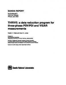
Figure 4. FRAP on patterned surfaces. Arrows in figure marked “bleach” indicate the direction of the grooves. Numbers below each image are the minutes following photobleaching. (Image sizes are 900 µm)
In a subsequent experiment, subtracted images were used to quantify recovery anisotropy on the patterned surfaces. Figure 5 shows a series of background subtracted images, from the time of bleaching (time 0) through 15 minutes of recovery. Line profiles of these images indicated significant recovery in the direction of the grooves, while recovery perpendicular to the 12
grooves was less significant, once again suggesting greater mobility of the lipids in the direction of the grooves.
Time 0
30sec
1 min
5 min
10 min
15 min
Figure 5. Background subtracted images of FRAP of supported bilayers on grooved substrata. Arrows indicate direction of grooves.
Supported lipid bilayers prepared with bicelles were formed successfully using twocomponent membranes of 1,2-diheptanoyl-sn-glycero-3-phosphocholine (DHPC) and 1,2dipalmitoyl-sn-glycero-3-phosphocholine (DPPC) at a molar of ratio of 1 : 2.8. Bicelles are disc-shaped lipid membrane structures, as shown in Figure 6, that utilize the lamellar bilayer structure favored by long chain PC (16 – 18 carbons) lipids combined with the high curvature structures, such as would be found at the edges of a lipid bilayer, favored by short chain PC (6 – 8 carbons) lipids. The two lipids should naturally phase separate as their chain lengths are considerably different in size. The lipid phases will tend to be gel-like for the long chain lipids and fluid-like for the short chain lipids. The supported membranes formed by fusion of bicelles to planar and textured silicon readily formed as detected by fluorescence microscopy (Figure 7).
40 bicelle
13
Figure 6. Schematic representation of a bicelle. Bicelle size: function of the molar ratio q = [long-chain]/[short chain] - several hundred angstroms
A
B
Figure 7. Confocal microscopy image of lipid bilayers formed on either (A) planar wafers or (B) nanotextured surfaces using bicelles made of a mix of 0.1 mol% bodipy-labeled short-chain lipid within DHPC with 0.5%
14
rhodamine-labeled long chain PC within DPPC. The first panel to the left shows rhodamine fluorescence, the one to the right shows bodipy fluorescence, and the third one shows the two panels superimposed on each other.
We attempted to photobleach the rhodamine-labeled long-chain lipid and the bodipylabeled short-chain lipid using the confocal microscope on the planar and nanostructured silicon. The fluorescence images of Figure 8 show that the long-chain lipids were slightly photobleached whereas the short-chain ones appeared resistant to photobleaching. Since photobleaching of the bodipy fluorophore should occur under the conditions of this experiment an alternative explanation is that the short-chain lipids may have recovered so rapidly that photobleaching was not detectable. Interestingly, no recovery was detected for the long-chain lipids up to 15 minutes post-photobleaching. Since the FRAP experiment was attempted at room temperature we intend to repeat it at 43 °C, which is higher than the transition temperature for the long-chain PC, to see if the biphasic structure of the membrane may be contributing to these results.
Figure 8. Confocal microscope images of the DHPC/DPPC bilayers on the planar silicon immediately after photobleaching.
15
Supported lipid bilayers on planar and nanostructured silicon – AFM imaging In situ AFM images of the 2.8 : 1 DPPC/DHPC bilayers on both planar and the nanostructured silicon yielded a number of interesting observations. Imaging was performed in situ in deionized water in tapping mode. On the planar substrate, the supported lipid membrane exhibited a biphasic structure of small 100 nm domains consisting of taller lipids embedded in a continuous fluid-like phase of smaller molecules (Figure 9). The taller domains were found to extend 13 – 17 Å above the surface of the fluid phase areas, consistent with the height difference between DPPC and DHPC. Defects in the bilayer facilitated measurement of the height of the membrane relative to the silicon surface, and was found to be 55 – 60 Å. The observed height of the membrane is consistent with that obtained in other AFM studies of similar lipid membranes.
5 um x 5
Figure 9. Tapping mode AFM images of 2.8 : 1 DPPC/DHPC on planar silicon. (A) White arrow points to hole in bilayer, red arrows point to regions of DPPC, yellow arrows point to regions of DHPC. (B) Heights: red 56 Å (hole in bilayer), and green - 14 Å (height difference between DPPC and DHPC).
16
On the nanostructured silicon surface the lipid membranes were found to span over the trenches between the raised line structures. Figure 10 shows the nanostructured surface (A) before and (B) after bilayer fusion in both height and amplitude modes. It is clear that the trenches have been covered in a bilayer membrane with undulated topology that is in registry with the corrugated substructure of the textured silicon. Small features 10’s of nanometers in size observed running down the center and sides of the raised lines in Figure 10A are presumably artifacts of the etching process. Figure 10B appears to show that the bilayer has conformal coverage over these smaller features.
A
B
Figure 10. Tapping mode AFM images of (A) nanostructured silica and (B) nanotextured silica with 2.8:1 DPPC:DHPC bilayer fused to it in height and amplitude modes (image size - 2 microns).
Topographic imaging of this unique composite structure finds that the membrane sags in between the line structures, much like how a cloth canopy might drape over a trellis or grated structure (Figure 11). Cross sectional analysis of the topography images revealed the membrane dips to a depth of ca. 40 nm, approximately one fifth the depth of the channel. The heights measured and features observed over the surface were fairly uniform. A schematic of the structure is shown in Figure 12, illustrating the draping of the membrane over the structure silicon. It is not know at this time if any bilayer material fills the channel below the channelspanning membrane nor the exact cause of the observed undulation of the bilayer on the silicon substrate.
17
Red: depth = 100 nm Green: distance = 170 nm
Red: depth = 25 nm Green: depth = 19 nm White: depth = 43 nm
Figure 11. Height profiles of nanostructured silicon (A) before and (B) after coating with 2.8 : 1 DPPC/DHPC bilayer.
360
100 200
Figure 12. Schematic of the nanocomposite architecture showing the lipid bilayer supported by the tops of the raised line features (360 nm pitch, 100 nm width) and spanning the 200 nm deep trenches. A close up of the bilayer interfacing the structured silicon is also shown for scale.
18
The AFM imaging was also able to resolve the gel-like domains of the DPPC aggregates from the fluid phase areas rich in DHPC within the sections of the membrane that span the raised lines of the silicon substrate. Figure 13 shows a highly magnified area that reveals features and heights that are consistent with the biphasic membrane observed in Figure 9, with the taller DPPC domains coexisting with the shorter DHPC-rich membrane. A hole in the bilayer can also be observed in Figure 13. Probing through the hole to evaluate subsurface features could not be performed due to size limitations of the relatively large AFM tip prohibiting entry into the hole. Lipid membrane upon the raised line features could not be resolved into their gel and fluid phase domains due to the roughness of the silicon surface. Quantification of the gel and fluid phases could reveal the physical preference of the lipid phases for the raised silicon features, or for convex and concave stretches of the membrane defined by the corrugated silicon substrate. This would be of interest for future research involving membrane-associated proteins, which typically have selective affinity for specific lipid phases, as well as in the general understanding of the mechanical behavior of lipid membranes.
hole in bilayer
Figure 13. High magnification of specific areas shows possible DPPC domains (red arrow) in DHPC-rich areas (purple arrow). Height difference between these two areas is 25 Å. Black box in image shows hole in bilayer.
19
Conclusions Through this work we have shown that lipid bilayer membranes can be readily configured with a nanostructured silicon surface and that the composite shows (1) the membrane spans over the corrugation of the silicon surface creating an undulated architecture, (2) lipid mobility was influenced by the patterned substructure, and (3) the structure is continuous over the micron to nanometer scale. This unique architecture provides a number of possibilities in the study of lipid membranes and device applications. While molecular mobility in the membrane can be directed through electrostatic, chemical, and physical interactions of tethered structures, through the use of this composite material we can now begin to explore the influence of the mechanics of membrane curvature and periodic structuring on the dynamics of membrane behavior. The asymmetric mobility of membrane lipids also means that embedded membrane proteins would also experience this compartmentalization in specific channels. If so, this could lead to addressable systems for membrane protein studies and novel biosensor applications. Further characterization and modification of the structure are continuing in an effort to realize some of the potential research and technological applications for this nanocomposite material.
Experimental Preparation of phospholipid vesicles Unilamellar vesicles were prepared using egg phosphatidylcholine (egg-PC). An 8 mM solution of egg-PC containing 0.5 mole% rhodamine labeled phosphatidyl-ethanolamine (PE) in chloroform was dried. The dried lipids were resuspended in 75 mM phosphate buffer, pH 7.0, and incubated at 63oC for 30 min, then extruded through 0.6 um polycarbonate filter.
Preparation of bicelles A 104 mM solution of 1,2-diheptanoyl-sn-glycero-3-phosphocholine (DHPC) containing 0.1 mole% bodipy-PE was prepared by drying the chloroform solution of the lipid, followed by dissolving in phosphate buffer saline (PBS), pH 7.4. Multilamellar vesicles of 72 mM 1,2-
20
dipalmitoyl-sn-glycero-3-phosphocholine (DPPC) containing 0.5 mole% PE-rhodamine in chloroform were prepared by drying then resuspending in PBS, and incubating at 63oC for 30 min. Bicelles were formed by adding DHPC to DPPC while mixing so that the final concentrations were 10 mM and 28 mM respectively [q ratio (molar ratio of long to short-chain PC) of 2.8:1].
Formation of SLB for fluorescence microscopy A silicon wafer (1 cm2) was cleaned by a quick dip in piranha and then thoroughly rinsed with water. The bilayer was formed by fusion of either phospholipid vesicles or bicelles by placing the wafer over a 40ul drop of the desired lipid suspension in a Petri dish for 10 minutes. The dish was then filled with distilled water and shaken gently to rinse away excess lipids. The silicon wafer was inverted and transferred to a small container while being maintained under water during this process.
Formation and imaging of bilayers with AFM Silicon wafer squares (1 cm x 1cm) were cleaned with piranha solution (30% H2O2/70% H2SO4), followed by liberal washing with deionized water. A 40 µL drop of the bicelle solution was then placed inside a clean petri dish and the inverted Si piece was placed atop the drop. The Si was gently shaken for 10 minutes to ensure formation of the bilayer. The sample was then rinsed by submerging the petri dish in a larger crystallizing dish filled with deionized water and the assembly gently shaken for 5 minutes. The sample was then flipped upright and the rinsing was repeated twice more. The Si sample was transferred to the AFM liquid cell by placing the O-ring of the liquid cell on the sample while under water. The O-ring was then clamped to the sample using tweezers and carefully removed from the water so that the sample surface remains submerged under water. The bottom of the sample was carefully dried with a towel, and the sample attached to an AFM puck on the scanner with double-sided tape. The liquid cell was then quickly assembled and filled with deionized water. AFM experiments were performed with a Nanoscope IIIa Multimode scanning probe microscope (Digital Instruments, Santa Barbara, CA). The images were acquired in tapping mode in solution using a commercially available liquid cell (Digital Instruments) with 120-µm 21
oxide-sharpened silicon nitride V-shaped cantilevers. The nominal spring constant of the cantilever was 0.35 N/m. Images were collected with the E-scanner, which has a maximum range of 15 µm x 15 µm, operating at a scan rate of 2 Hz. Data was collected with 256 data points per line.
References i) Alberts B, Bray D, Lewis J, Raff M, Roberts K, Watson JD. 1994. Molecular Biology of The Cell. New York: Garland Publishing. ii) Burns CJ, Field LD, Morgan J, Petteys BJ, Prashar J, Ridley DD, Sandanayake KRAS, Vignevich V. 2001. Components for Tethered Bilayer Membranes: Synthesis of Hydrophilically Substituted Phytanol Derivatives. Aust. J. Chem. 54:431 - 438. iii) Anrather D, Smetazko M, Saba M, Alguel Y, Schalkhammer T. 2004. Supported membrane nanodevices. J. Nanosci. Nanotech. 4:1 - 22. iv) Melzak KA, Ellar DJ, Gizeli E. 2004. Interaction of Cytolytic Toxin CytB with a Supported Lipid Bilayer: Study Using an Acoustic Wave Device. Langmuir 20:1386 - 1392. v) Stora T, Lakey JH, Vogel H. 1999. Ion-Channel Gating in Transmembrane Receptor Proteins: Functional Activity in Tethered Lipid Membranes. Angew. Chem. Int. Ed. 38:389 392. vi) New RRC. 1990. Liposomes. Rickwood D, Hames BD, editors. New York: Oxford University Press. 301 p. vii)
Gohon Y, Popot J-L. 2003. Membrane protein-surfactant complexes. Curr. Opin. Coll. Interf. Sci. 8:15 - 22.
viii)
Tamm LK, McConnell HM. 1985. Supported Phospholipid Bilayers. Biophys. J. 47:105 -
113. ix) Kalb E, Frey S, Tamm LK. 1992. Formation of supported planar bilayers by fusion of vesicles to supported phospholipid monolayers. Biochim. Biophys. Acta 1103:307 - 316. x) Krull UJ. 1987. Planar artificial biomembranes optimized for biochemical assay. Anal. Chim. Acta 197:203 - 215.
22
xi) Koenig BW, Krueger S, Orts WJ, Majkrzak CF, Berk NF, Silverton JV, Gawrisch K. 1996. Neutron Reflectivity and Atomic Force Microscopy Studies of a Lipid Bilayer in Water Adsorbed to the Surface of a Silicon Single Crystal. Langmuir 12:1343 - 1350. xii) Feng VZ, Granick S, Gewirth AA. 2004. Modification of a Supported Lipid Bilayer by Polyelectrolyte Adsorption. Langmuir 20:8796 - 8804. xiii) Krishna G, Schulte J, Cornell BA, Pace R, Wieczorek L, Osman PD. 2001. Tethered Bilayer Membranes Containing Ionic Reservoirs: The Interfacial Capacitance. Langmuir 17:4858 4866. xiv) Wagner ML, Tamm LK. 2000. Tethered Polymer-Supported Planar Lipid Bilayers for Reconstitution of Integral Membrane Proteins: Silane-Polyethyleneglycol-Lipid as a Cushion and Covalent Linker. Biophys. J. 79:1400 - 1414. xv) Kugler R, Knoll W. 2002. Polyelectrolyte-supported lipid membranes. Bioelectrochemistry 56:175 - 178. xvi) Seitz M, Park CK, Wong JY, Israelachvili JN. 2001. Long-Range Interaction Forces between Polymer-Supported Lipid Bilayers Membranes. Langmuir 17:4616 - 4726. xvii) Seitz M, Ter-Ovanesyan E, Hausch M, Park CK, Zasadzinski JA, Zentel R, Israelachvili JN. 2000. Formation of Tethered Supported Bilayers by Vesicle Fusion onto Lipopolymer Monolayers Promoted by Osmotic Stress. Langmuir 16:6067 - 6070. xviii) Yoshina-Ishii C, Boxer SG. 2003. Arrays of mobile tethered vesicles on supported lipid bilayers. J. Am. Chem. Soc. 125:3696 - 3697. xix) Sharma MK, Jattani H, Lane M. Gilchrist J. 2004. Bacteriorhodopsin conjugates as anchors for supported membranes. Bioconj. Chem. 15:942 - 947. xx) Györvary E, Wetzer B, Sleytr UB. 1999. Lateral Diffusion of Lipids in Silane-, Dextran-, and S-Layer-Supported Mono- and Bilayers. Langmuir 15:1337 - 1347. xxi) Hughes AV, Goldar A, Gerstenberg MC, Roser SJ, Bradshaw J. 2002. A hybrid SAM phospholipid approach to fabricating a 'free' supported lipid bilayer. Phys. Chem. Chem. Phys. 4:2371 - 2378. xxii) Zaidi SH, Chu A-S, Brueck SRJ. 1996. Optical properties of nanoscale, one-dimensional silicon grating structures. J. Appl. Phys. 80:6997 - 7008.
23
xxiii) Brueck SRJ, Zaidi S, Chen X, Zhang Z. 1998. Interferometric lithography - from periodic arrays to arbitrary patterns. Microelec. Engn. 41/42:145 - 148. xxiv) Zaidi SH, Brueck SRJ. 1999. Interferometric lithography for nanoscale fabrication. Proc. SPIE-Int. Soc. Opt. Eng. 3618:2 - 8. xxv) O'Brien, M. J., Bisong P, Ista LK, Rabinovich EM, Garcia AL, Sibbett SS, Lopez GP, Brueck SRJ. 2003. Fabrication of an integrated nanofluidic chip using interferometric lithography. J. Vac. Sci. Tech. B 21:2941 - 2945.
24
DISTRIBUTION: 5
Prof. Gabriel P. Lopez Department of Chemical and Nuclear Engineering University of New Mexico Albuquerque, New Mexico 87131
2
Prof. S. R. J. Brueck Center for High Technology Materials University of New Mexico Albuquerque, New Mexico 87106
10 1 1 1 1 1 2
MS 1413 1413 1413 1413 0123 9018 0899
D. Sasaki A. Slade P. Dressendorfer T. Michalske D. Chavez, 1011 Central Technical Files, 8945-1 Technical Library, 9616
25