LM741. Operational Amplifier. General Description. The LM741 series are
general purpose operational amplifi- ers which feature improved performance
over ...
Offset Nulling Circuit. 00934107. August 2000. LM741. Operational. Amplifier ... ±15V. ±15V. Output Short Circuit Duration. Continuous. Continuous. Continuous.
See AN-450 âSurface Mounting Methods and Their Effect on Product .... and packing materials meet the provisions of the Customer Products Stewardship.
LM741. Operational Amplifier. General Description. The LM741 series are
general purpose operational amplifi- ers which feature improved performance
over ...
SNOSC25C –MAY 1998–REVISED MARCH 2013. LM741 Operational Amplifier.
Check for Samples: LM741. 1FEATURES. DESCRIPTION. The LM741 series ...
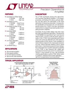
The LT®1001 significantly advances the state-of-the- ... LT1001. 1001fb.
LT1001AM/883. LT1001AC. LT1001M/LT1001C. SYMBOL PARAMETER.
акÑÐ¸Ð²Ð½Ð¸Ñ FBAR ÑÑлÑÑÑÑв. ÐлÑÑÐ¾Ð²Ñ ... electromechanical coupling coefficient of FBAR resonators .... the expression for transconductance gm takes the form. g v.
The op-amp is a linear amplifier with Vout ∝ Vinp. The DC open-loop ... Cheap
IC versions of operational amplifiers are readily available, making their use
popular in any .... Remove the lead connecting the free end of R1 to ground.
Connect ...
The LMH6733 is a triple, wideband, operational ... speed and low power are
required. ... Connection Diagram .... All Three Amps Enabled, No Load ..... To
match a 150Ω source would require using a 1050Ω feedback resistor and would
result ...
The design of such complex circuit is discussed in chapter 6; here we will ...
macromodel to analyze the principles of OPAMP based circuits and their
operation.
basic analog building block OTA circuit. The designed. OTA circuit is tested in .... K. Kim, O. Kwon, J. Seo, Nano-scale Device. Modeling and Simulation: FinFET, ...
NTE941 Integrated Circuit Operational Amplifier Description: The NTE941 is a general purpose operational amplifier in an 8–Lead TO5 Metal Can type package
Sign in. Loading⦠Whoops! There was a problem loading more pages. Whoops! There was a problem previewing this document
macromodel to analyze the principles of OPAMP based circuits and their
operation. ... Since we are assuming that the circuit is linear, among other
representations, we can describe the ..... In analog integrated circuits design, it is
difficult.
Sign in. Page. 1. /. 1. Loading⦠Page 1 of 1. File: Pdf operational amplifier. Download now. Click here if your downlo
Circuit designing has been done on S-edit and ... The CMOS Op Amp circuit in
Fig.2.1 is a Two Stage .... [5] Sanjeev Gupta, “Electronics Devices and Circuits,”.
Texas Instruments (TI) reserves the right to make changes to its products or to
discontinue any ..... Instruments' data book, Amplifiers, Comparators, and Special.
Functions, is ..... stage was perfectly symmetrical and the transistors were
perfec
n Comparator and buffer ... g The ideal op-amp is characterized by seven
properties ... n The ideal op-amp acts as a perfect internal voltage source with no.
... scientific devices. Operational Amplifiers, more commonly known as Op-amps, are .... compared the obtained parameters of the device through simulation to the specifications for the device. Design Issues ... 6 Illustration of the design relationsh
Nov 23, 2014 - Operational amplifier is widely used in electronic devices today as it ..... of Electrical, Electronics & Communication Engineering, 2(6), 330â336.
8(a) using MOS grounded resistors. Fig. 12. Oscilloscope photograph of the V1 and V2 of the oscillator of Fig. 6(a). Vertical 1 V/div; horizontal 20 μs/div. 54.
4th Akshay Kumar Maan. 8.98 · Griffith University. Abstract. The neuronal algorithms process the information coming from the natural environment in analog ...
The basic comparator circuit is an op-amp arranged in the open-loop ... Voltage
transfer characteristic of non-inverting comparator with non-zero reference.
Description. The LM741 series are general purpose operational amplifi- ...
applications. 8-DIP. 1. Internal Block Diagram. LM741. Single Operational
Amplifier ...
www.fairchildsemi.com
LM741 Single Operational Amplifier
Features
Description
• • • • •
The LM741 series are general purpose operational amplifiers. It is intended for a wide range of analog applications. The high gain and wide range of operating voltage provide superior performance in intergrator, summing amplifier, and general feedback applications.
Short circuit protection Excellent temperature stability Internal frequency compensation High Input voltage range Null of offset
Absolute Maximum Ratings (TA = 25°C) Parameter Supply Voltage Differential Input Voltage Input Voltage Output Short Circuit Duration Power Dissipation
2
Symbol
LM741
Unit
VCC
±18
V
VI(DIFF)
30
V
VI
±15
V
-
Indefinite
-
PD
500
mW
Operating Temperature Range
TOPR
0 ~ + 70
°C
Storage Temperature Range
TSTG
-65 ~ + 150
°C
LM741
Electrical Characteristics (VCC = 15V, VEE = - 15V. TA = 25 °C, unless otherwise specified) Parameter
Symbol
Input Offset Voltage
VIO
Input Offset Voltage Adjustment Range
VIO(R)
Input Offset Current Input Bias Current Input Resistance
Typ.
Max.
RS≤10KΩ
-
2.0
6.0
RS≤50Ω
-
-
-
VCC = ±20V
-
±15
-
mV
-
-
20
200
nA
-
-
80
500
nA
0.3
2.0
-
MΩ
±12
±13
-
V
VCC =±20V, VO(P-P) =±15V
-
-
-
VCC =±15V, VO(P-P) =±10V
20
200
-
-
-
25
-
RL≥10KΩ
-
-
-
RL≥10KΩ
-
-
-
RL≥10KΩ
±12
±14
-
RL≥10KΩ
±10
±13
-
70
90
-
RS≤50Ω, VCM = ±12V
-
-
-
VCC = ±15V to VCC = ±15V RS≤50Ω
-
-
-
VCC = ±15V to VCC = ±15V RS≤10KΩ
77
96
-
-
0.3
-
µs
-
10
-
%
-
-
-
MHz
VCC =±20V
-
GV
ISC VCC = ±20V
Output Voltage Swing
Common Mode Rejection Ratio
Power Supply Rejection Ratio
VO(P-P)
CMRR
PSRR
Transient
Rise Time
tR
Response
Overshoot
OS
Bandwidth
mV
IIO
RL≥2KΩ
Output Short Circuit Current
Unit
Min.
VI(R)
Large Signal Voltage Gain
LM741
IBIAS RI
Input Voltage Range
Conditions
VCC = ±15V
RS≤10KΩ, VCM = ±12V
Unity Gain
-
BW
V/mV
mA
V
dB
dB
Slew Rate
SR
Unity Gain
-
0.5
-
V/µs
Supply Current
ICC
RL= ∞Ω
-
1.5
2.8
mA
Power Consumption
PC
VCC = ±20V
-
-
-
VCC = ±15V
-
50
85
mW
3
LM741
Electrical Characteristics ( 0°C ≤TA≤70 °C VCC = ±15V, unless otherwise specified) Parameter Input Offset Voltage Input Offset Voltage Drift Input Offset Current Input Offset Current Drift Input Bias Current Input Resistance Input Voltage Range
Figure 2. Input Resistance and Input Capacitance vs Frequency
Figure 3. Input Bias Current vs Ambient Temperature
Figure 4. Power Comsumption vs Ambient Temperature
Figure 5. Input Offset Current vs Ambient Temperature
Figure 6. Input Resistance vs Ambient Temperature
5
LM741
Typical Performance Characteristics (continued)
6
Figure 7. Normalized DC Parameters vs Ambient Temperature
Figure 8. Frequency Characteristics vs Ambient Temperature
Figure 9. Frequency Characteristics vs Supply Voltage
Figure 10. Output Short Circuit Current vs Ambient Temperature
Figure 11. Transient Response
Figure 12. Common-Mode Rejection Ratio vs Frequency
LM741
Typical Performance Characteristics (continued)
Figure 13. Voltage Follower Large Signal Pulse Response
Figure 14. Output Swing and Input Range vs Supply Voltage
7
LM741
Mechanical Dimensions Package
1.524 ±0.10
#5 2.54 0.100 5.08 MAX 0.200 7.62 0.300
3.40 ±0.20 0.134 ±0.008
+0.10
0.25 –0.05 +0.004
0~15°
8
0.010 –0.002
3.30 ±0.30 0.130 ±0.012 0.33 0.013 MIN
0.060 ±0.004
#4
0.018 ±0.004
#8 9.60 MAX 0.378
#1
9.20 ±0.20 0.362 ±0.008
(
6.40 ±0.20 0.252 ±0.008
0.46 ±0.10
0.79 ) 0.031
8-DIP
LM741
Ordering Information Product Number
Package
Operating Temperature
LM741CN
8 DIP
0 ~ + 70°C
9
LM741
LIFE SUPPORT POLICY FAIRCHILD’S PRODUCTS ARE NOT AUTHORIZED FOR USE AS CRITICAL COMPONENTS IN LIFE SUPPORT DEVICES OR SYSTEMS WITHOUT THE EXPRESS WRITTEN APPROVAL OF THE PRESIDENT OF FAIRCHILD SEMICONDUCTOR INTERNATIONAL. As used herein: 1. Life support devices or systems are devices or systems which, (a) are intended for surgical implant into the body, or (b) support or sustain life, and (c) whose failure to perform when properly used in accordance with instructions for use provided in the labeling, can be reasonably expected to result in a significant injury of the user.
2. A critical component in any component of a life support device or system whose failure to perform can be reasonably expected to cause the failure of the life support device or system, or to affect its safety or effectiveness.
www.fairchildsemi.com 7/12/00 0.0m 001 Stock#DSxxxxxxxx 2000 Fairchild Semiconductor International