Oct 13, 2011 - package types, die sizes, compositions and positions ..... This will lead to prolonged service life ... S.K. Seo, M.G. Cho, and H.M. Lee, J. Mater.
Journal of ELECTRONIC MATERIALS, Vol. 40, No. 12, 2011
DOI: 10.1007/s11664-011-1782-y Ó 2011 TMS
Localized Recrystallization Induced by Subgrain Rotation in Sn-3.0Ag-0.5Cu Ball Grid Array Solder Interconnects During Thermal Cycling HONGTAO CHEN,1 JING HAN,1 and MINGYU LI1,2,3 1.—Department of Materials Science and Engineering, Shenzhen Graduate School, Harbin Institute of Technology, Shenzhen 518055, China. 2.—State Key Laboratory of Advanced Welding Production Technology, Harbin Institute of Technology, Harbin 150001, China. 3.—e-mail: myli@ hit.edu.cn
The evolution of microstructures and grain orientations of a Pb-free solder interconnect during thermal cycling significantly affects its mechanical properties and failure modes. Thus, Sn-3.0Ag-0.5Cu ball grid array assemblies were subjected to thermal cycling to study the thermomechanical responses of the solder interconnects. The orientations and microstructures of the solder interconnects were studied by optical microscopy with cross-polarized light and scanning electron microscopy with an electron backscattered diffraction analysis system. Localized recrystallization behavior was observed in Pb-free solder interconnects during thermal cycling. Closer examination of the very early stage of recrystallization in the same solder interconnect revealed that the subgrains appeared before the formation of the recrystallized grains, and the orientations of the small recrystallized grains separated by high-angle grain boundaries evolved from the initial orientations by subgrain rotation. The localized recrystallization produced fine-grained microstructures during thermal cycling, providing an additional deformation mechanism for the solder interconnects, i.e., grain boundary sliding, which would have been impossible prior to recrystallization. The grain orientation has a strong effect on damage generation and the subsequent failure mode; initiation and propagation of cracks could be facilitated by the intrinsic anisotropic thermomechanical responses of the differently oriented grains, leading to a change in the crack propagation path and corresponding failure mode. Key words: Pb-free, soldering, electron backscattered diffraction (EBSD), recrystallization
INTRODUCTION Sn-Pb solder has been extensively used as an interconnect material in electronic packaging for many years. However, Pb has been prohibited for use in electronic products by legislation because of environmental and health concerns.1 Most Pb-free solders consist mainly of Sn-based alloys, in which the concentration of Sn is generally over 95 wt.%.1,2 Therefore, the properties of Sn determine the (Received January 19, 2011; accepted September 21, 2011; published online October 13, 2011)
2470
overall performance of Pb-free solder interconnects. It has been reported that a small Pb-free solder interconnect is typically composed of one or a few grains,3–10 and the solder interconnect always exhibits extremely strong anisotropy due to the body-centered tetragonal lattice structure of Sn with the c-axis being only about half of the other two axes.4 The linear coefficient of thermal expansion (CTE) of b-Sn along the [001] axis (c-axis) is reported to be about twice that along the [100] (a-axis) and [010] axes (b-axis); similarly, the Young’s modulus along the c-axis is about three times larger than that along the other two axes.11–13 This may lead to
Localized Recrystallization Induced by Subgrain Rotation in Sn-3.0Ag-0.5Cu Ball Grid Array Solder Interconnects During Thermal Cycling
early failure of solder interconnects if these grains have an unfavorable orientation with respect to the interfacial intermetallic compound (IMC) or substrate, for example, with the c-axis of the Sn grain parallel to the connecting Cu6Sn5 IMC.4–6 Furthermore, even internal stress alone could lead to grain boundary damage induced by CTE mismatch arising from the intrinsic anisotropy of differently oriented grains in a solder interconnect.13 Therefore, the thermomechanical responses of solder interconnects may be quite different from one another due to the varied orientations and corresponding stress–strain states depending on the different package types, die sizes, compositions and positions of interconnects, etc.6,14–16 Thus, the orientation of each grain plays an important role in dictating the overall performance of small-scale Pb-free solder interconnects, leading to deformation and failure mechanisms quite different from those of bulk solder. Electronic packages are frequently subjected to temperature variations caused by power on/off switches and environmental changes. Solder interconnects often fail during thermal cycling due to stress and strain concentrations caused by CTE mismatches between different packaging materials, and thus solder interconnect reliability under thermal cycling is always a serious concern in electronic products.2,17 In recent years, Pb-free solder interconnect reliability has been extensively studied, with most research focusing on the formation and evolution of the IMCs, especially at the interface, due to their inherent brittle nature.3,18–20 However, cracks are frequently observed in the solder bulk instead of along the interfacial IMCs in thermal cycling.4,5,11–16 Thus, it is also important to study the solder alloy in terms of orientation, microstructure, and mechanical properties, in order to obtain better understanding of the damage evolution and underlying failure mechanism of Pb-free solder interconnects. It is worth noticing that the orientation, microstructure, and corresponding mechanical properties are not invariable after the solidification of solder interconnects, and they can evolve dramatically during thermal cycling due to the combined effect of temperature and stress concentration.21–24 It has been reported that microstructure is significantly changed by recrystallization that occurs in areas with high strain energy in Pb-free solder interconnects during thermal cycling, and cracks are initiated and propagated intergranularly in the recrystallized microstructure, leading to the final failure of the solder interconnects.5–10,25–28 Recrystallization can be defined as the formation of a new grain structure in a deformed material by the formation and migration of high-angle grain boundaries driven by the stored energy of deformation.29 However, it has been pointed out that the decrease of the stored energy can proceed effectively by recovery in high stacking fault energy metals such
2471
as Sn, and the Pb-free solder interconnect is more likely to form subgrains by dislocation rearrangement (polygonization) to decrease the Gibbs free energy during creep deformation;30,31 therefore, recrystallization should take place only under restricted loading conditions: dynamic loading where the strain hardening is more efficient than recovery.27 It is assumed that most of the microstructural evolution arises from continuous recrystallization, in which parent grain orientations rotate gradually to form the recrystallized grains during cyclic deformation.5 Incremental recrystallization, driven by the release of elastic strain energy, was also proposed to account for the orientation evolution in a thermomechanically fatigued lap solder joint.21 However, the underlying formation mechanism of recrystallization and its role in the failure of Pb-free solder interconnects are still not well understood. Therefore, the recrystallization behavior and corresponding changes in microstructure and orientation, which significantly affect the thermal, mechanical, and electrical properties and failure modes of solder interconnects, need to be further studied. In this work, we studied the microstructrual changes induced by localized recrystallization in Pbfree ball grid array (BGA) solder interconnects during thermal cycling. Based on the experimental observations and analysis described in this paper, the formation mechanism of recrystallization and the cracking behavior facilitated by the anisotropic thermomechanical responses of differently oriented grains are discussed, contributing to better understanding of the underlying deformation and failure mechanisms of Pb-free solder interconnects. EXPERIMENTAL PROCEDURES The component used in this study was a chipscale packaged (CSP) BGA with 228 Sn-3.0Ag-0.5Cu solder balls at 0.5 mm pitch. The solder ball size was 0.3 mm in diameter. The package dimension was 12 mm 9 12 mm 9 1.1 mm with a 10 mm 9 10 mm 9 0.27 mm die attached. An electrolytic NiAu surface finish was applied on the package-side substrate. The BGA packages were soldered onto the non-solder mask defined (NSMD) Cu pad of a FR-4 printed circuit board (PCB) using a typical reflow profile with peak temperature of 245°C and duration of 1 min at temperature above 217°C. The BGA assemblies were then subjected to thermal cycling between 0°C and 100°C for different times. The dwell time at each temperature extreme was 15 min, and the ramp rate was about 60°C/min. At varying intervals, different specimens were taken out and cross-sectioned to check the microstructural evolution of the solder interconnects. Also, in situ observations were performed on the same crosssectioned interconnect at the outermost row of the BGA (not mounted in epoxy to remove the mechanical constraints) in the as-reflowed state and
2472
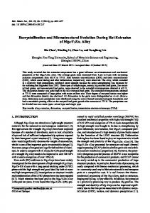
at a very early stage of recrystallization to track the evolution of orientation directly, as shown in Fig. 1. Although this may not result in the exact same stress and strain distribution as in a real BGA assembly due to the partial damage in preparing the crosssectioned samples, it keeps the structural integrity to the utmost extent, giving insight into what actually occurs in the interior microstructure of the BGA solder interconnects. To observe the orientation of the solder interconnects, the specimens were crosssectioned, mounted with epoxy, ground with SiC papers, and then polished sequentially with 6-lm, 4-lm, 2-lm, 1-lm, and 0.5-lm diamond suspensions. Final polishing was performed carefully with 0.05lm colloidal silica suspension. Optical microscopy with cross-polarized light was used in the study for quick characterization of the grain orientations in solder interconnects, with each color corresponding to an individual orientation.
Chen, Han, and Li
Orientation imaging microscopy (OIM) using an EDAX/TSL system installed on a scanning electron microscope (SEM, HITACHI-S4700) was adopted to determine the orientation details quantitatively. To generate good electron backscattered diffraction (EBSD) patterns for OIM analysis, a Au coating was sputtered onto the cross-section of the specimen to minimize charging, and the artifacts introduced by dicing and grinding had to be carefully removed by the polishing steps. The OIM data were collected using TSL OIM Data Collection 5.2 using a 30-kV beam. Orientation maps, pole figures, and misorientation plots were generated using TSL OIM analysis 5.2 software. The obtained datasets were cleaned by incorporating lower confidence index points with higher confidence index points using a nearest-neighbor correlation technique. The small Cu6Sn5 and Ag3Sn IMC particles were removed from the orientation maps. RESULTS
Fig. 1. Schematic of cross-sectioned sample used for in situ observation.
Corresponding cross-polarized images and EBSD orientation maps of the cross-sections of two typical as-reflowed solder interconnects are shown in Fig. 2. Although the orientation characteristics varied significantly in different Pb-free BGA solder interconnects, the interconnects were typically composed of a few (Fig. 2a) and sometimes even only one grain (Fig. 2b), which is in good agreement with results obtained in previous studies.11,15,32 This indicates that nucleation of the Sn grains is suppressed because more latent heat of freezing is released during the solidification process due to the high entropy of fusion of tetragonal Sn (14 J/mol K).33–35 However, fast growth of b-Sn dendrites could be achieved with the significant undercooling normally associated
Fig. 2. Cross-polarized light images and EBSD orientation maps of as-reflowed solder interconnects: (a) multi- and (b) single-grained (Color figure online).
Localized Recrystallization Induced by Subgrain Rotation in Sn-3.0Ag-0.5Cu Ball Grid Array Solder Interconnects During Thermal Cycling
Fig. 3. Misorientation angle distribution of solder interconnect in Fig. 2a.
with Sn and Sn-rich solder alloys, leading to the few grains present in the solder interconnects.7 At the same time, stacking faults such as twins or other minority orientations with low-energy boundaries are highly likely to form in the solidification process.34 Of the 16 solder interconnects scanned by OIM in this experiment, 6 of them had only one grain, while the rest had 2–5 grains with over 50% twin misorientations in the grain boundaries. As shown in Fig. 3, almost all high-angle grain boundaries observed in the multigrain specimens were twin-type (57° to 63°) misorientations, which is in good agreement with reported results.33,34,36 As shown in Fig. 2a, occasionally some mottled regions with two or three alternating colors in the cross-section were observed in the EBSD orientation map. Grains in these mottled regions are easily mistaken for small grains under cross-polarized light microscopy. With further characterization by the EBSD method, however, it could be clearly seen that the observed mottled areas were the intersecting surface of large interlaced grains, because the boundaries separating the interpenetrating grains are always indented. Generally, distinct colors under cross-polarized light microscopy correspond to different orientations; however, the cross-polarized light image is not always in good agreement with the EBSD orientation map. Sometimes, as shown in Fig. 2a, b, grain boundaries delineated clearly by EBSD method cannot be discerned under cross-polarized light, while high contrast between two grains under crosspolarized light does not necessarily mean that a high-angle grain boundary exists between them. Furthermore, a small angle rotation of the polarizer may reveal a quite different grain structure, and it is difficult to distinguish different orientations merely by color or contrast under cross-polarized light. Therefore, observation under cross-polarized light can only be used as a supplementary means to characterize grain orientations, whereas EBSD is a more accurate method in describing these details.
2473
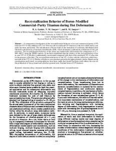
The cross-polarized image and EBSD orientation map of the cross-section of the solder interconnect after 2815 thermal cycles are shown in Fig. 4a and b, respectively. In a localized region we observed many small grains with varied colors (each color represents an individual orientation), which are different from the grains in the mottled regions in as-reflowed solder interconnects (Fig. 2a). The sizes of the small equiaxed grains with various orientations range from 5 lm to 30 lm, indicating that localized recrystallization has taken place in the Pb-free solder interconnect. These results agree well with those obtained in previous studies.5,6,25,27 As shown in Fig. 4c, it can be seen clearly from the grain boundary map that the recrystallized region is roughly delineated with high-angle grain boundaries. It should be noted that many small grains with low-angle grain boundaries (indicated by blue lines) and boundaries with misorientations between 10° and 15° (indicated by green lines) were located around the recrystallized microstructures. These grain boundaries are likely to be at the transition stage from low angle to high angle. Similar results were reported by Bieler and coworkers.5 From the pole figure shown in Fig. 4b, d, three predominant orientations of nonrecrystallized grains were observed. It is highly likely that the original as-reflowed grains spread from the few predominant orientations to the random orientations in the localized recrystallized region, in which subgrain rotation plays an important role in the deformation behaviors of the solder interconnects.5,25,37 As shown in Fig. 5a, only one grain with blue orientation (near [110]) was observed in the as-reflowed solder interconnect underneath the chip corner for in situ observation. After 1150 thermal cycles between 0°C and 100°C, the contamination and uneven surface of the cross-section made the indexing of EBSD patterns very difficult. Therefore, careful, light repolishing was performed on the cross-section to remove the contamination and obtain a smooth surface for indexing. After 1150 thermal cycles (Fig. 5b) some subgrains and grains with obviously different orientations from the initial texture were formed, mainly near the corners and interfaces with the two joining pads, where microcracks and obvious extrusions or intrusions were observed with the imposed cyclic stress due to the CTE mismatch between different packaging materials, as shown in Fig. 6. It can be clearly observed in the pole figures of Fig. 5a–c that the initial grain with blue orientation near [110] spread towards the newly formed grains with pink or orange orientation near [001]. Most of these newly formed subgrains rotated about a few degrees from the initial dominant orientation, as shown in the orientation map of Fig. 5b. The misorientation measured along the white line in the EBSD orientation map of the solder interconnect in Fig. 5c shows that the misorientation increases gradually from the unchanged grain (retaining almost the same orientation as the
2474
Chen, Han, and Li
Fig. 4. (a) Cross-polarized image, (b) EBSD orientation map, (c) grain boundary map, and (d) nonrecrystallized region of solder interconnect after 2815 thermal cycles between 0°C and 100°C (Color figure online).
as-solidified grain) to the subgrains, and then it starts to increase significantly towards the recrystallized grains, as shown in Fig. 7. In the grain boundary map of the solder interconnect shown in Fig. 5b we can see that many low-angle boundaries were formed (indicated by blue lines). This is in good agreement with literature reports,5 which assume that the orientation evolution arises from continuous recrystallization and that low-angle boundaries can gradually transform into high-angle boundaries by absorbing dislocations. Some of these subgrains, for example, in the upper left corner of the solder interconnect, can rotate further to become obvious recrystallized grains separated by large-angle grain boundaries (indicated by pink color), as shown in Fig. 5b. Similarly, the stripe-like subgrain at the upper right corner in Fig. 5b will finally evolve into recrystallized grains as indicated by pink or orange color on further rotation after 4600 thermal cycles, as shown in Fig. 5c. More recrystallized grains with high-angle grain boundaries were formed as the thermomechanical fatigue continued. In this experiment, it is interesting to note that cracking was observed in an interconnect at a 45° angle with respect to the horizontal pad after 2815 thermal cycles, as shown in Fig. 8a. Detailed characterization by EBSD revealed that the solder interconnect originally comprised two differently oriented grains with a high-angle grain boundary at an angle of 45° with the horizontal pad, and the cracks mainly followed the narrow band of localized recrystallization along the original grain boundary,
which was roughly delineated by high-angle grain boundaries (indicated by red lines), as shown in Fig. 8c. This indicates that the internal stress arising from the CTE mismatch between differently oriented grains can change the crack path, facilitating crack propagation along the grain boundary. ANALYSIS AND DISCUSSION Facilitated Cracking by Anisotropic Thermomechanical Responses of Differently Oriented Grains By comparing the damage extent of solder interconnects in Figs. 4 and 8 (both of which experienced the same thermal cycling history, i.e., 2815 thermal cycles between 0°C and 100°C), we assume that the cracking of the solder interconnect in Fig. 8 was facilitated by grain boundary sliding caused by the anisotropic thermomechanical responses of the two differently oriented grains. From Fig. 8b, it can clearly be seen from the inverse pole figure that the grain in the lower left corner had [100] (a-axis) close to the sample normal, while the other grain in the upper right corner had [001] (c-axis) parallel to the sample normal. There is a large difference in CTE between the c-axis and a-axis for the anisotropic Sn metal; the CTE in the [001] direction is nearly twice that in the [100] or [010] direction (at 30°C, the CTEs in the a-axis and c-axis are 16.5 9 10 6 K 1 and 32.4 9 10 6 K 1, respectively).12,38 Furthermore, the easiest slip direction in Sn is [001] on {100} or {110} planes.39 Consequently, the large CTE
Localized Recrystallization Induced by Subgrain Rotation in Sn-3.0Ag-0.5Cu Ball Grid Array Solder Interconnects During Thermal Cycling
2475
Fig. 5. EBSD orientation maps, grain boundary maps, and (001) pole figures of solder interconnects for in situ observation: (a) as-reflowed, (b) after 1150 thermal cycles, and (c) after 4600 thermal cycles (Color figure online).
Fig. 6. SEM images of solder interconnect in Fig. 5b.
2476
Fig. 7. Misorientation measured along the path (indicated by white line) from the unchanged grain to recrystallized grains in EBSD orientation maps of the solder interconnect in Fig. 5c.
mismatch between the two differently oriented grains leads to the subsequent facilitated cracking. Therefore, grain orientation has a great effect on damage generation and the subsequent failure mode. This may not result in catastrophic failure with the internal stress caused by anisotropic thermomechanical responses alone. However, it should be noted that a high-angle grain boundary could be assumed as a potential cracking site (or preferred grain boundary sliding site) due to its high energy.32 If the high-angle boundary coincides with a high stress concentration area, it will accelerate initiation and propagation of cracks or change the cracking path and corresponding failure mode, leading to fast degradation of solder interconnects. On the contrary, low-energy boundaries (low angle and coincidence site lattice) may contribute to enhance the thermal fatigue properties by suppressing grain boundary sliding due to their low energy.28 Therefore, it is important and necessary to incorporate the orientation details to obtain a better understanding of the effect of anisotropy of Sn grains on Pb-free solder interconnect reliability. Localized Recrystallization Induced by Subgrain Rotation Recrystallization has been observed in pure Sn and Sn-rich solders subjected to compressive deformation and annealing, and it can occur in pure Sn even at room temperature; however, the process can be retarded by IMC particles in Sn-based solders by pinning of grain boundaries.40 The formation mechanism of recrystallization in Pb-free solder interconnects has been discussed by Telang et al.,21 and it is assumed that the driving force for incremental recrystallization is the release of elastic strain energy by changing the initial dominant orientation to a more elastically compliant twinrelated orientation, which was present in the initial
Chen, Han, and Li
texture as a minority orientation. Their observations and analyses were based on a single shear lap joint, which may have different microstructures and orientations compared with practical solder interconnects due to the effects of size, metallization, and solidification conditions. Furthermore, shear lap joints have less complex stress–strain states than surface-mount solder interconnects because of their simple geometry. Therefore, they may not account for the recrystallization which occurs in practical interconnects, especially those comprising only one grain. It is suggested that other recrystallization mechanisms, such as continuous recrystallization, may be involved due to the different microstructures and the interaction between the complicated geometries and the crystal orientations in practical interconnects.5 The observation of localized recrystallization behavior in Pb-free BGA solder interconnects in the present study is in good agreement with previous studies on practical solder interconnects due to the similar size and structures.5–10,24–28,32 Based on what has been observed at the very beginning of the recrystallization, as shown in Fig. 5a–c, the dynamic recrystallization should have been induced by subgrain rotation; i.e., the newly formed recrystallized grains evolved from subgrains by gradual rotation under cyclic stress during the thermomechanical fatigue process. Similar results were also reported in literature,5,6 and it is assumed that the presence of low-angle boundaries is a starting point for continuous recrystallization, in which the dislocations are absorbed into these boundaries to enlarge the misorientation between the neighboring grains, and then the lowangle boundaries could be gradually transformed into high-angle boundaries.29 A network of low-angle grain boundaries was formed, most likely as a consequence of recovery. These changes were observed to initiate early in the course of the thermal cycling tests. However, the low-angle grain boundaries observed in this study may not be the same as dislocation walls separating cell structures, which are typical products of polygonization; cell structures with dislocation walls should be much smaller and may not be clearly observed under optical microscopy or even SEM, while the subgrains in this study are relatively large. It is likely that the large subgrain that we observed showing almost the same crystallographic orientations is a group of small cell structures or subgrains (see the lower right corner of the solder interconnect in Fig. 5b) with slightly different misorientations with respect to each other, which could continue to evolve into larger subgrains by rotation and coalescence with the their neighbors as the cyclic fatigue continues (see the upper right corner of the solder interconnect in Fig. 5b, c). As a consequence, the misorientation between neighboring subgrains is enlarged after the coalescence. Some of these subgrains could finally become the recrystallized grains as the misorientation increases incrementally
Localized Recrystallization Induced by Subgrain Rotation in Sn-3.0Ag-0.5Cu Ball Grid Array Solder Interconnects During Thermal Cycling
2477
Fig. 8. (a) EBSD orientation map, (b) nonrecrystallized region, and (c) grain boundary map of a cracked solder interconnect with two differently oriented grains after 2815 thermal cycles between 0°C and 100°C (Color figure online).
because of the deformation-induced subgrain rotation in slip or sliding processes. However, transmission electron microscopy (TEM) characterization needs to be done to further study the detailed subgrain microstructures. The subgrain rotation requires that the dislocations move and climb relatively freely, which would be favored by the elevated temperature. The possibility of subgrain rotation during recrystallization has been confirmed thermodynamically and kinetically.37 In addition, the IMC particles may play an important role in the microstructure and orientation evolution. Compared
with the dispersed fine IMC particles in the as-solidified microstructure, the coarsened particles during thermal cycling are less able to pin low-angle grain boundaries, leading to larger subgrains with higher crystallographic misorientation within the Sn grains.25 Intergranular Cracking of Solder Interconnect in Thermomechanical Fatigue In this study, crack initiation and propagation occurred almost exclusively at the high-angle grain
2478
Chen, Han, and Li
Fig. 9. Fractography of cracked solder interconnect after thermal cycling.
boundaries of the recrystallized microstructures produced by the process of thermomechanical fatigue, and grain boundary decohesion was frequently observed along the crack path. In fact, the final failure of solder interconnects under thermal cycling should be the combined effect of creep and fatigue. Especially for the high homologous temperature of solder interconnects (0.56T/Tm 0.76T/ Tm for Sn-3.0Ag-0.5Cu in the present study), creep may play a more important role in the fracture of solder interconnects. During creep, intergranular crack initiation is determined by the synergistic actions of grain boundary sliding and vacancy diffusion towards regions with high hydrostatic tensile stress; this leads to formation of voids along the grain boundaries and grain boundary triple lines, and subsequent coalescence to form cracks.41 Solder interconnects with fewer grains can resist grain boundary sliding due to the shortage of grain boundaries, while fine grains facilitate grain boundary damage, especially for the high working temperature of Pb-free solder interconnects.32 Therefore, compared with the original few large grains in the as-solidified interconnects, the larger number of newly formed, fine grains with mobile high-angle grain boundaries in the recrystallized microstructures are more susceptible to grain boundary sliding when stress is concentrated. Moreover, the CTE mismatch between differently oriented grains could also contribute to the intergranular cracking. On the other hand, cracking also involves plastic flow to alternately blunt and sharpen the crack tip under the cyclic fatigue stress, as evidenced by the presence of classic fatigue striations on fractography of solder interconnects, as shown in Fig. 9. Therefore, the intergranular cracking in solder interconnects should be the consequence of interaction between grain boundary cracks caused mainly by grain boundary sliding and fatigue cracks induced by local plastic deformation.42 Furthermore, the coarsening of IMC particles in the recrystallized microstructures could also lead to
degradation of mechanical properties.43,44 Thus, significant plastic deformation is localized in the recrystallized region, and the fatigue crack propagation process is rapidly accelerated immediately after the recrystallization occurred in Pb-free solder interconnects. That is to say, the deformation behavior has been changed fundamentally once the recrystallization has taken place in solder interconnects, and recrystallization provides an additional deformation mechanism for Pb-free solder interconnect, i.e., grain boundary sliding, which would have been impossible for the as-solidified microstructure. Solder interconnects with varied orientations show different thermomechanical responses or failure modes. However, the size, shape, and orientation of the grains vary from interconnect to interconnect after solidification. The orientations of solder interconnects are hard to control due to the complicated solidification process, and they could be changed dramatically by the recrystallization process during thermomechanical fatigue. Nevertheless, the addition of second-phase particles to solder alloys may contribute to postpone recrystallization and subsequent crack initiation and propagation along the recrystallized grain boundaries by pinning the grain boundaries and the movement of dislocations. This will lead to prolonged service life for electronic products and is certainly worth more detailed investigation. CONCLUSIONS The orientation and microstructure changes occurring in localized recrystallization in Pb-free BGA solder interconnects during thermal cycling were investigated in this study. EBSD observation on the orientation evolution in the same interconnect revealed that the initial grain with orientation near [110] evolved toward the newly formed (sub)grains with orientation near [001] by subgrain rotation. Compared with the original few large grains in the as-solidified solder interconnect, the
Localized Recrystallization Induced by Subgrain Rotation in Sn-3.0Ag-0.5Cu Ball Grid Array Solder Interconnects During Thermal Cycling
fine grains produced after recrystallization significantly facilitated grain boundary sliding, which could be a very important plastic deformation mode at relatively high homologous temperature of operation. Actually, recrystallization provided an additional deformation mechanism for solder interconnect, which would have been impossible for the as-solidified microstructure. Moreover, after recrystallization, the recrystallized regions are more easily deformed than the surrounding material, and strain localization can be anticipated in these regions, which accelerates fatigue damage in the recrystallized region accumulated by grain boundary sliding during thermomechanical fatigue. In addition, the anisotropic thermomechanical response of Sn grains with different orientations could facilitate initiation and propagation of cracks along the grain boundaries, which may lead to different failure modes of solder interconnects with varied orientations. ACKNOWLEDGEMENTS The work is financially supported by the National Science Foundation under Grant No. 50905042, the Natural Scientific Research Innovation Foundation of Harbin Institute of Technology (HIT. NSRIF. 2009139), Shenzhen Fundamental Research Program (JC201005260172A), and the Guangdong Province Lead-free Roadmap Project (2009A0802 4009-5). The authors would like to thank Gao Shang for his help with EBSD measurement. REFERENCES 1. K. Zeng and K.N. Tu, Mater. Sci. Eng. R 38, 55 (2002). 2. M. Abtew and G. Selvaduray, Mater. Sci. Eng. R 27, 95 (2000). 3. D.R. Frear, J.W. Jang, J.K. Lin, and C. Zhang, JOM 53, 28 (2001). 4. J.G. Lee, A. Telang, K.N. Subramanian, and T.R. Bieler, J. Electron. Mater. 31, 1152 (2002). 5. B. Zhou, T.R. Bieler, T.K. Lee, and K.C. Liu, J. Electron. Mater. 39, 2669 (2010). 6. T.R. Bieler, H. Jiang, L.P. Lehman, T. Kirkpatrick, E.J. Cotts, and B. Nandagopal, IEEE Trans. Compon. Packag. Technol. 31, 370 (2008). 7. D.W. Henderson, J.J. Woods, T.A. Gosselin, J. Bartelo, D.E. King, T.M. Korhonen, M.A. Korhonen, L.P. Lehman, E.J. Cotts, S.K. Kang, P. Lauro, D.Y. Shih, C. Goldsmith, and K.J. Puttlitz, J. Mater. Res. 19, 1608 (2004). 8. S. Terashima, K. Takahama, M. Nozaki, and M. Tanaka, Mater. Trans. 45, 1383 (2004). 9. S. Terashima and M. Tanaka, Mater. Trans. 45, 681 (2004). 10. T.T. Mattila, V. Vuorinen, and J.K. Kivilahti, J. Mater. Res. 19, 3214 (2004). 11. S.B. Park, R. Dhakal, L.P. Lehman, and E.J. Cotts, ASME InterPACK ’05 Proceedings, San Francisco, July 17–22 (2005). 12. M.A. Matin, E.W.C. Cohen, W.P. Vellinga, and M.G.D. Geers, Scripta Mater. 53, 927 (2005). 13. S.B. Park, R. Dhakal, L. Lehman, and E. Cotts, Acta Mater. 55, 3253 (2007).
2479
14. T.K. Lee, K.C. Liu, and T.R. Bieler, J. Electron. Mater. 38, 2685 (2009). 15. S.K. Seo, M.G. Cho, and H.M. Lee, J. Mater. Res. 25, 1950 (2010). 16. B. Zhou, R.T. Bieler, T.K. Lee, and K.C. Liu, J. Electron. Mater. 38, 2702 (2009). 17. R. Darveaux and K. Banerji, IEEE Trans. Compon. Hybrids Manuf. Technol. 15, 1013 (1992). 18. K.S. Kim, S.H. Huh, and K. Suganuma, J. Alloy. Compd. 352, 226 (2003). 19. M. He, Z. Chen, and G.J. Qi, Acta Mater. 52, 2047 (2004). 20. H.T. Ma, T.K. Lee, D.H. Kim, H.G. Park, S.H. Kim, and K.C. Liu, IEEE Trans. Compon. Packag. Manuf. Technol. 1, 714 (2011). 21. A.U. Telang, T.R. Bieler, A. Zamiri, and F. Pourboghrat, Acta Mater. 55, 2265 (2007). 22. A.U. Telang, T.R. Bieler, J.P. Lucas, K.N. Subramanian, L.P. Lehman, Y. Xing, and E.J. Cotts, J. Electron. Mater. 33, 1412 (2004). 23. Y. Mutoh, J. Zhao, Y. Miyashita, and C. Kanchanomai, Solder. Surf. Mt. Technol. 14, 37 (2002). 24. J.J. Sundelin, S.T. Nurimi, and T.K. Lepisto¨, Mater. Sci. Eng. A 474, 201 (2008). 25. T.K. Lee, B. Zhou, L. Blair, K.C. Liu, and T.R. Bieler, J. Electron. Mater. 39, 2588 (2010). 26. S. Dunford, S. Canumalla, and P. Viswanadham, 54th Electronic Components and Technology Conference Proceedings, Las Vegas, June 1–4 (2004). 27. T.T. Mattila and J.K. Kivilahti, IEEE Trans. Compon. Packag. Technol. 33, 629 (2010). 28. S. Terashima, T. Kobayshi, and M. Tanaka, Sci. Technol. Weld. Join. 13, 732 (2008). 29. R.D. Doherty, D.A. Hughes, F.J. Humphreys, J.J. Jonas, D.J. Jensen, M.E. Kassner, W.E. King, T.R. McNelley, H.J. McQueen, and A.D. Rollett, Mater. Sci. Eng. A 238, 219 (1997). 30. D. Hardwick, C.M. Sellars, and W.J.Mc.G. Tegart, J. Inst. Met. 90, 21 (1961). 31. D. McLean and M.H. Farmer, J. Inst. Met. 85, 41 (1956). 32. S. Terashima, T. Kohno, A. Mizusawa, K. Arai, O. Okada, T. Wakabayashi, M. Tanaka, and K. Tatsumi, J. Electron. Mater. 38, 33 (2009). 33. L.P. Lehman, Y. Xing, T.R. Bieler, and E.J. Cotts, Acta Mater. 58, 3546 (2010). 34. A.U. Telang and T.R. Bieler, Scripta Mater. 52, 1027 (2005). 35. S. Terashima and M. Tanaka, Sci. Technol. Weld. Join. 14, 468 (2009). 36. L.P. Lehman, S.N. Athavale, T.Z. Fullem, A.C. Giamis, R.K. Kinyanjui, M. Lowenstein, K. Mather, R. Patel, D. Rae, J. Wang, Y. Xing, L. Zavalij, P. Borgesen, and E.J. Cotts, J. Electron. Mater. 33, 1429 (2004). 37. J.C.M. Li, J. Appl. Phys. 33, 2958 (1962). 38. W.B. Pearson, A Handbook of Lattice Spacings and Structure of Metals and Alloys, Vol. 2 (London: Pergamon, 1958). 39. A.U. Telang, T.R. Bieler, S. Choi, and K.N. Subramanian, J. Mater. Res. 17, 2294 (2002). 40. P. Lauro, S.K. Kang, W.K. Choi, and D.Y. Shih, J. Electron. Mater. 32, 1432 (2003). 41. U. Krupp, Fatigue Crack Propagation in Metals and Alloys: Microstructural Aspects and Modelling Concepts (Weinheim: Wiley-VCH, 2007). 42. C. Kanchanomai and Y. Mutoh, Fatigue Fract. Eng. Mater. Struct. 30, 443 (2006). 43. H.T. Chen, M. Mueller, T.T. Mattila, J. Li, X.W. Liu, K.-J. Wolter, and M. Paulasto-Kro¨ckel, J. Mater. Res. 26, 2103 (2011). 44. I. Dutta, D. Pan, R.A. Marks, and S.G. Jadhav, Mater. Sci. Eng. A 410–411, 48 (2005).