May 23, 2011 - Yin,1 J. Zhao,1 A. N. Cleland,1 John M. Martinis,1 and J. J. A. ... black shield at the sample temperature, we found about an order of magnitude ...
Loss and decoherence due to stray infrared light in superconducting quantum circuits R. Barends,1 J. Wenner,1 M. Lenander,1 Y. Chen,1 R. C. Bialczak,1 J. Kelly,1 E. Lucero,1 P. O’Malley,1 M. Mariantoni,1 D. Sank,1 H. Wang,1 T. C. White,1 Y. Yin,1 J. Zhao,1 A. N. Cleland,1 John M. Martinis,1 and J. J. A. Baselmans2
arXiv:1105.4642v1 [cond-mat.mes-hall] 23 May 2011
1
Department of Physics, University of California, Santa Barbara, CA 93106, USA 2 SRON Netherlands Institute for Space Research, Sorbonnelaan 2, 3584 CA Utrecht, The Netherlands (Dated: May 25, 2011)
We find that stray infrared light from the 4 K stage in a cryostat can cause significant loss in superconducting resonators and qubits. For devices shielded in only a metal box, we measured resonators with quality factors Q = 105 and qubits with energy relaxation times T1 = 120 ns, consistent with a stray light-induced quasiparticle density of 170-230 µm−3 . By adding a second black shield at the sample temperature, we found about an order of magnitude improvement in performance and no sensitivity to the 4 K radiation. We also tested various shielding methods, implying a lower limit of Q = 108 due to stray light in the light-tight configuration.
Quantum information processing in superconducting circuits is performed at very low temperatures, so energy loss due to quasiparticles is expected to vanish because their density diminishes exponentially with decreasing temperature. As energy relaxation times saturate for superconducting quantum circuits and planar resonators, reaching values on the order of 1-10 µs [1–4], recent experiments have suggested that this may be due to excess non-equilibrium quasiparticles; measurements on phase qubit coherence [5, 6], tunneling in charge qubits [7], resonator quality factors [3, 4] and quasiparticle recombination times [8, 9] are compatible with an excess quasiparticle density on the order of 10-100 µm−3 , possibly arising from stray light, cosmic rays, background radioactivity, or the slow heat release of defects. In this Letter, we demonstrate that stray infrared light gives significant loss in resonators and qubits, and is sometimes the dominant limitation in our present experiments. We also show quantitatively how a combination of infrared shielding techniques removes the influence of stray infrared light, and that the required shielding is beyond what is generally used. The effectiveness of the various techniques is investigated by methodically changing and testing them. With our new light-tight setup, the quality factors of Al superconducting resonators improve dramatically by a factor of 20, as shown in Fig. 1. We also show that shielding improves phase qubit coherence. Loss in a superconducting resonator with frequency f is controlled by the quasiparticle density nqp [10] (for kT ≪ hf ) s α 2∆ nqp 1 = (1) Q π hf D(EF )∆ with ∆ the energy gap, D(EF ) the two-spin density of states, and α the kinetic inductance fraction, which depends on geometry. Importantly, excess quasiparticles can limit quality factors, in particular at the low temperatures at which resonators and qubits are operated.
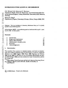
Measurements on the temperature dependence of resonator quality factors indicate the presence of an additional loss term, as shown in Fig. 1. Here we plot quality factors of coplanar waveguide (CPW) Al resonators. The open symbols are measured when simply placing the sample in a sample box in a cryostat, with no special measures against stray light. Above a temperature of 200 mK the quality factors decrease exponentially, consistent with a thermal quasiparticle density (dashed line, Eq. 1). At low temperatures a plateau value of 105 is
FIG. 1: (Color online) The quality factors of four halfwave coplanar waveguide Al resonators versus sample stage temperature, measured in a setup without effort to shield stray infrared light (open symbols) and with an improved lighttight sample stage (closed symbols). Resonance frequencies lie between 3.8 and 4.5 GHz. Eq. 1 is plotted for an exponentially decreasing quasiparticle density (dashed line), excess quasiparticle density of 230 µm−3 (bottom solid line) and 10 µm−3 (top solid line). Kinetic inductance fraction α = 0.28 for these devices. Inset shows a halfwave resonator capacitively coupled to a feedline.
2
radiator
coax filter
50 mK stage
sample box coating
outer can magnetic shield cryostat
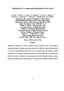
FIG. 2: (Color online) Schematic representation of the lighttight sample stage: the sample box is mounted inside a larger box on the 50 mK stage, closed off by an outer can. The inner surfaces of the sample box lid and outer can are coated with a blackbody absorber (blue). Coaxial readout lines are filtered using 50 Ω matched metal powder filters (green). The entire sample stage lies within a magnetic shield (grey), attached to the cryostat’s 4 K stage. The radiator is used for Fig. 4.
observed, consistent with an excess quasiparticle density of 230 µm−3 (red solid line). When using our newly designed sample stage, quality factors of the same resonators improve to 2 · 106 (closed symbols). This shows that stray infrared light is limiting the quality factors in the old design, and that our new design is light-tight. We will discuss our light-tight setup, test the effectiveness of its parts, and show that the influence of stray light can be fully removed. Stray infrared light enters the sample mount through the lid joint and connectors, generating quasiparticles in the sample. p It can be shown that under strong loading [11]: nqp ∝ P/∆, where P is the absorbed radiation power for which hf > 2∆. Al is particularly sensitive to stray light: with a gap frequency of 88 GHz, 96 % of the power of a 4.2 K blackbody can be absorbed. Moreover, quasiparticle recombination is slow in Al [8, 9]. In order to quantify the influence of stray light, we use halfwave CPW Al resonators with a film thickness of 52 nm, which are coupled capacitively to a feedline (inset Fig. 1). This allows us to extract the unloaded quality factor Qi from the feedline transmission. We measure quality factors at high power to reduce the influence of two-level systems [3, 4]. We use halfwave resonators, where the central line is galvanically isolated, to rule out quasiparticle outdiffusion and hot electrons. Measurements are done in an adiabatic demagnetization refrigerator (ADR), with a base temperature of 50 mK. The sample space is shielded by a cryogenic magnetic shield, attached to the 4 K stage. The transmission is measured using a vector network analyzer, a low noise cryogenic and room temperature amplifier. Our light-tight sample stage uses a ‘box-in-a-box’ design, following Baselmans et al. [12]. A schematic repre-
sentation, shown in Fig. 2, gives a maximally light-tight design. The sample box is placed in a larger box in which the photon temperature is equal or very close to the desired electron temperature. This is achieved by blocking routes for stray light to enter the sample space as well as using black coating on the inner surfaces. The black coating is a key ingredient, and consists of a mixture of silica powder, fine carbon powder and 1 mm SiC grains in stycast epoxy [13]. The SiC grains create a rough surface to prevent an angular dependence of reflection, and the coating has an absorptivity of 90 % in the 0.3-2.5 THz range [13]. The coax filters have a 50 Ω impedance, and use bronze and carbon powder as absorber along with a NbTi central conductor, following Ref. [14]. At 4.2 K, the transmission up to 20 GHz is given by S = Af , with A = −0.18 dB/GHz. At 4 GHz the attenuation is below 1 dB, while we estimate that 4.2 K radiation is reduced by ∼ 30 dB to a power below 100 fW, which is an upper limit due to additional absorption by the carbon. The sample stage is attached to the 50 mK cold finger of the ADR. For readout, we use two 0.86 mm diameter CuNi coaxial cables, connected between the 4 K stage and the coax filters on the sample stage. Having shown that the new design reduces stray light and improves resonator quality factors, we next describe the influence of key parts of the setup. We test the effect of the: I) outer can, II) black coating on the outer can and/or sample box lid, III) coax filters, and IV) seams in the outer box. The influence of stray light is quantified by continuously measuring the quality factors of the resonators while warming up the cryostat at the 4 K stage, bathing the sample stage in a hot thermal photon bath. While doing so, the sample stage temperature is always kept below 150 mK where the quality factor is unaffected. The effectiveness of the shielding methods is shown in Fig. 3. When not using any shielding (outer can, coax filters, or a coated sample box lid), a loss of 10−5 is found, which increases strongly with increasing cryostat temperature (red squares). When adding a coated sample box lid and coax filters, a loss on the order of 10−6 is found at the lowest cryostat temperatures (red dots). However, here the loss also increases with elevating cryostat temperature. Light-tightness is somewhat improved when adding an uncoated can or covering the sample box with Al tape (purple triangles). The largest improvement is observed when using a coated can, although a small cryostat temperature dependence is still visible. Only when using a coated can and a coated sample box lid is the lowest loss achieved and the dependence on the cryostat temperature fully removed (blue stars). When a 0.5 mm gap is introduced a small temperature dependence returns. We find that the effect of the coax filters on the light-tightness is insignificant for our experiment. The data follow only approximately a pure blackbody radiation dependence for the unshielded case. For a pure blackbody: P ∝ T 4 , hence 1/Q ∝ T 2 (solid line). With
3
-4
radiator temperature (K)
10
3
Old
10
20
50
(1/ s)
15
-5
10
1
10
1/T
resonator loss - 1/Q
i
New
5 0
-6
10
3
10
20
30
cryostat temperature (K)
-7
10
3
5
10
15
20
25 30
cryostat temperature (K)
FIG. 3: (Color online) The loss of an Al resonator versus cryostat temperature, showing the influence of different shielding techniques when going from no infrared shielding (�) to fully shielded (★). The sample stage temperature is kept below 150 mK. Variations in the presence of a coated sample box lid and coax filters (closed symbols, red colors): no can present (●), sample box covered with Al tape (N) and uncoated can present (H). Variations in the presence of a coated outer can (open symbols, purple and blue colors): coated can floating on 0.5 mm spacers (3), uncoated sample box lid and no coax filters (D), uncoated lid and filters (�) coated lid and no filters (�). Influence of a hot blackbody (solid), hot blackbody filtered with a cut-off frequency at 1 THz (dashed), filtered with a cut-off frequency at 100 GHz (dotted) and no dependence (dash dotted).
increasing shielding the slope of the data decreases, consistent with the sample stage acting as a low pass filter. We model this as a first order filter with transfer function: 1/(1 + [f /fc ]2 ), with cut-off frequency fc . We find that for the unshielded case fc is on the order of 1 THz (dashed line) (Eq. 1). With Al tape or an uncoated can: fc ∼ 100 GHz (dotted line). With each additional shielding step the loss drops — indicating enhanced insensitivity to stray light — and the slope decreases — indicating a decrease of the cut-off frequency. This suggests that stray low frequency photons are the main source of infrared-related loss in partly shielded environments. The data in Fig. 3 demonstrate that a box-in-a-box design with black coating is needed to ensure the removal of the influence of stray light, and that anything less is insufficient. An uncoated outer can increases the quality factor to above 106 at 3 K, but does not completely remove the influence of stray light. Only when using an
FIG. 4: (Color online) Phase qubit energy relaxation rate measured in the light-tight setup versus cryostat temperature (★), and measured without the presence of a coated outer can versus temperature of a radiator (�) (see Fig. 2). The sample stage temperature is kept below 150 mK.
outer can and coating the inner surfaces of the can and sample box is there no dependence on the cryostat temperature. This temperature is varied from 3 K to 23 K, increasing the stray light power by 103 . Moreover, a tight fitting of the outer can is unnecessary as a 0.5 mm gap has only a small effect on the quality factors at 3 K. Using a coated can is more effective than having it tightly fitting. The coax filters are insignificant for our mount, possibly due to the use of dissipative CuNi coaxial lines. However, the filters are still useful as they ensure thermalization of the inner wire. The resonator quality factors improve from 105 to 2 · 106 , as shown in Fig. 1 (closed symbols). This value is believed to be unrelated to stray light because of its insensitivity to the cryostat temperature. We estimate a lower limit of 108 due to stray light, assuming a level equal to the noise at 23 K in Fig. 3 and extrapolating to 3 K. The remaining loss mechanism may be radiation loss or excess quasiparticles from some other mechanism, as suggested by recent number fluctuation measurements [9]. In this case the quasiparticle density has been reduced to 10 µm−3 (blue solid line) or below. In order to quantify the influence of stray light on qubits, we also measure the energy relaxation time T1 of a phase qubit versus mounting method. With the filters and black outer can in place, we find a T1 of 450 ns, consistent with typical values for phase qubits. In addition, we find no increase of the energy relaxation rate with increasing cryostat temperature, as shown in Fig. 4. In contrast, when only the outer can is removed T1 drops to 120 ns. This value is compatible with a quasiparticle density of 170 µm−3 [15], close to the value of 230 µm−3 found for the resonators. Without an infrared shield, T1
4 decreases very rapidly with increasing cryostat temperature. To identify the influence of stray infrared light on the qubit, we instead use a blackbody radiator, which is placed behind the magnetic shield (see Fig. 2) and heated up to a stable temperature. We emphasize that the radiator has a weaker influence than the cryostat. The energy relaxation rate clearly increases with the radiator temperature. The decrease in T1 as well as the temperature dependence in Fig. 4 show that stray light considerably diminishes qubit coherence. It is therefore vitally important for qubit coherence to use a light-tight sample stage, as shown in Fig. 2. In summary, when placing a superconducting resonator or qubit in a simple mounting box, the quality factor and energy relaxation times can be significantly influenced by stray infrared light. Moreover, stray light is often the dominant limitation in present experiments, introducing an excess quasiparticle density between 170230 µm−3 . Using a combination of shielding methods we have improved quality factors from 105 to 2·106 and qubit energy relaxation times from 120 to 450 ns, with measurements now being unaffected by stray light. This shows that the influence from stray infrared can be removed using a ‘box-in-a-box’ design with black absorbers. We estimate a lower limit of 108 for resonator quality factors due to stray light in the present configuration. This work was supported by IARPA under ARO award W911NF-09-1-0375 and by the Rubicon program of the Netherlands Organisation for Scientific Research (NWO).
[1] A. A. Houck, J. A. Schreier, B. R. Johnson, J. M. Chow, J. Koch, J. M. Gambetta, D. I. Schuster, L. Frunzio, M. H. Devoret, S. M. Girvin, R. J. Schoelkopf. Phys. Rev.
Lett. 101, 080502 (2008). [2] P. Bertet, I. Chiorescu, G. Burkard, K. Semba, C. J. P. M. Harmans, D. P. DiVincenzo, and J. E. Mooij, Phys. Rev. Lett. 95, 257002 (2005). [3] H. Wang, M. Hofheinz, J. Wenner, M. Ansmann, R. C. Bialczak, M. Lenander, E. Lucero, M. Neeley, A. D. OConnell, D. Sank, M. Weides, A. N. Cleland, and J. M. Martinis, Appl. Phys. Lett. 95, 233508 (2009). [4] R. Barends, N. Vercruyssen, A. Endo, P. J. de Visser, T. Zijlstra, T. M. Klapwijk, P. Diener, S. J. C. Yates, and J. J. A. Baselmans, Appl. Phys. Lett. 97, 023508 (2010). [5] J. M. Martinis, M. Ansmann, and J. Aumentado, Phys. Rev. Lett. 103, 097002 (2009). [6] M. Lenander, H. Wang, R. C. Bialczak, E. Lucero, M. Mariantoni, M. Neeley, A. D. O’Connell, D. Sank, M. Weides, J. Wenner, T. Yamamoto, Y. Yin, J. Zhao, A. N. Cleland, and J. M. Martinis, arXiv:1101.0862. [7] M. D. Shaw, R. M. Lutchyn, P. Delsing, and P. M. Echternach, Phys. Rev. B 78, 024503 (2008). [8] R. Barends, S. van Vliet, J. J. A. Baselmans, S. J. C. Yates, J. R. Gao, and T. M. Klapwijk, Phys. Rev. B 79, 020509 (2009). [9] P. J. de Visser, J. J. A. Baselmans, P. Diener, S. J. C. Yates, A. Endo, and T. M. Klapwijk, Phys. Rev. Lett. 106, 167004 (2011). [10] D. C. Mattis and J. Bardeen, Phys. Rev. 111, 412 (1958). [11] A. Rothwarf and B. N. Taylor, Phys. Rev. Lett. 19, 27 (1967). [12] J. J. A. Baselmans and S. J. C. Yates, AIP Conf. Proc. 1185, 160 (2009). [13] T. O. Klaassen, J. H. Blok, J. N. Hovenier, G. Jakob, D. Rosenthal, and K. J. Wildeman, Proc. IEEE 10th Int. Conf. on THz Electronics, p. 32 (2002). [14] F. P. Milliken, J. R. Rozen, G. A. Keefe, and R. H. Koch, Rev. Sci. Instrum. 78, 024701 (2007). [15] √ Energy decay rate due to quasiparticles [5]: 1/T1 = 2(∆/E10 )3/2 nqp /RCD(EF )∆. R = 115 Ω, C = 1 pF and E10 = 6.7 GHz.