The 33rd Annual Conference of the IEEE Industrial Electronics Society (IECON) Nov. 5-8, 2007, Taipei, Taiwan
Loss Minimization Control for Doubly-Fed Induction Generators in Variable Speed Wind Turbines Ahmed G. Abo- Khalil, Hong-Geuk Park, Dong-Choon Lee
Seung-Pyo Ryu, Se-Hyun Lee
Dept. of Electrical Eng., Yeungnam Univ. 214-1, Daedong, Gyeongsan, Gyeongbuk, Korea
[email protected]
Electro-Mechanical Research Institute Hyundai Heavy Industry Co. Ltd, Gyeongki, Korea
[email protected]
Abstract- In this paper, a novel control algorithm for minimizing the operating loss of doubly fed induction generators (DFIG) for variable speed wind turbines is presented. At first, the generator losses are modeled, which consist of the copper loss and the iron losses. Then, a stator d-axis current is derived which minimizes the total generator loss. Based on this current, the stator reactive power level is controlled. The experimental results for a 3kW DFIG wind turbine simulator show that the amount of power saving approaches to 23% at 5[m/s] wind speed, which is more significant at low wind speed. I.
Fig. 1. Power flow in wind power generation system.
INTRODUCTION
Wind power has proven to be a potential clean and renewable source for generation of electricity with minimal environmental impact. In recent years, there has been a widespread growth in the exploitation of wind energy, which requires the development of larger and more robust wind turbine systems [1]. It is preferable to run the wind energy generation system (WEGS) at a variable generator speed to maximize the captured wind power. For the maximum power point tracking (MPPT), the optimum tip-speed ratio [2] or search-based method [1] have been used, which adjust the active power reference of the generators to the optimum value for the given wind speed. Compared with the constant speed operation, variable speed operation of wind turbines with the MPPT provides 10~15[%] higher energy output, lower mechanical stress, and less power fluctuation [3]. Since the WEGS consists of different mechanical components like drive train, gearbox, generator, and so on, numerous losses can be found in the system. The total WEGS losses are divided into two main categories, mechanical and electrical losses. A general power flow diagram for a WEGS is shown in Fig. 1. Recently, attention has been paid to improve the operating efficiency of generators in WEGS by minimizing the electrical loss. The DFIG is now one of the main generators for high-power variable-speed wind energy conversion systems. It has many advantages compared with the squirrel-cage induction generator [4]-[6]: the rotor-side converter operates at the slip frequency and the power converter processes only ± 30% of the rated power of the generator with the converter cost reduced; the generated active and reactive power can be controlled independently. Control of DFIG loss has been reported in [7] and [8]. In [7], the stator d-axis current for minimum copper loss is derived and then used to obtain the reactive power reference. However,
1-4244-0783-4/07/$20.00 ©2007 IEEE
Fig. 2. Configuration of DFIG wind power systems.
the main target in [7] is the generator active and reactive power control in steady state and transients without showing the effect of the injected reactive power on the copper loss reduction. In [8], the loss reduction is achieved by sharing the generator and grid reactive power between the two converters on the rotor circuit. However, the sharing ratio is a function of the filter capacitor current, power factor, and generator parameters, which make it difficult to determine the optimum sharing ratio for all power factors and operating conditions. In this paper, a control algorithm is proposed to minimize the total loss of the DFIG. The copper and iron losses of the DFIG are modeled as a function of the stator flux and d-axis current. Then, a stator d-axis current which minimizes the total generator losses is derived. The simulation results for a 2[MW] DFIG show a reduction in the generator loss up to 30% at 5[m/s] wind speed. The experimental results for a 3kW wind turbine simulator show energy saving of 23% at the same wind speed. II. MODELING AND CONTROL OF DFIG Configuration of the overall wind generation system using DFIG is shown in Fig. 2. The stator of DFIG is directly connected to the grid and the rotor is connected through the back-to-back PWM converters.
1109
Grid Turbine Gearbox 1:n
PWM Converter
Vdc
t r
iar
Encoder
ibr v a
e
1 s
r-+
sl
Ps P *+-
Power controller
iqre
Q +
Fig. 3. Equivalent circuits of DFIG.
vdqs = Rsidqs + where
d λdqs + jωe λdqs dt
(1) (2)
Lm : Magnetizing inductance; Ls : Stator self-inductance;
λdqs : Stator d-q axis flux linkages;
idqs : Stator d-q axis currents; vdqs : Stator d-q axis voltages;
ωe : Source angular frequency. For coordinate transformation, the angle between two reference frames is required. The phase angle θ e of the stator flux vector which rotates at the synchronous speed is given by
λ
s dqs
= ∫ (v
s dqs
θ e = tan −1
s s dqs
− R i )dt
λ λsds s qs
(3)
(4)
where the superscript ‘s’ indicates quantities in the stationary reference frame. Also, the rotor fluxes and voltages can be expressed as λdqr = Lr idqr + Lm idqs (5)
vdqr = Rr idqr +
d λdqr + j (ωe − ωr )λdqr dt
where Lr : Rotor self-inductance;
λdqr : Rotor d-q axis flux linkages;
idqr : Rotor d-q axis currents; vdqr : Rotor d-q axis voltages;
vc
sl
q-axis Current Controller
iqre *
vqre
e
vdr
e
Reactive power controller
i
e* dr
i dr +
d-axis Current Controller
Fig. 4. Control. block diagram of DFIG.
Fig. 3 shows the d-q equivalent circuits of DFIG. In a synchronously rotating d-q reference frame, the stator fluxes and voltages can be expressed as [9]
λdqs = Ls idqs + Lmidqr
-
vb
SVPWM
-
Qs *
e
sl
j
ωr : Rotor angular frequency.
For transformation of the rotor quantities, the slip angle ( θ sl ) is required, which can be expressed as θ sl = θ e − θ r , where θ r is the rotor angular position. The generator torque is expressed as P Lm (7) Te = 1.5 (λds iqr − λqs idr ) 2 Ls and the stator active and reactive power can be expressed as 3 (8) Ps = (vqsiqs + vds ids ) 2 3 (9) Qs = (vqsids − vdsiqs ) 2 III. CONTROL OF ROTOR-SIDE CONVERTER Stator-flux oriented vector control is usually adopted in DFIG control, where the stator flux vector is aligned with the d-axis. In this case, the d-q axis fluxes can be expressed as (10) λqs = 0, and λds = λs The q-axis component of the rotor current can control either the generator torque or the stator active power. On the other hand, the rotor d-axis current component can control directly the stator reactive power. Considering vds = 0 from (10) and substituting the rotor current which results from (1) and (10) into (8) and (9), the stator active and reactive power can be expressed as 3 Lm (11) Ps = − vqs iqr 2 Ls
(6)
Qs =
where
3 Lm vqs (ims − idr ) 2 Ls
ims
(12)
is the magnetizing current, which is constant for
constant λds . Therefore, the above equations show that stator active and reactive power can be controlled independently by controlling iqr and idr, respectively. Fig. 4 shows the schematic configuration of the DFIG wind
1110
i
i i
i
i
i
dλqm
(18) + ωe λdm dt where Ri is the equivalent iron loss resistance. The stator daxis flux in a synchronous reference frame is nearly constant as the stator is connected to the stiff grid with a constant voltage and constant frequency, while the q-axis flux is nearly zero in the d-axis flux oriented control. Therefore the flux variation in synchronous reference frame can be neglected and the current flowing in the core loss branch can be expressed as Ri idi = −ωeλqm (19)
Ri iqi =
3 Lm ⋅ ⋅ vqs 2 Ls
Ri iqi = ωe λdm Fig. 5. Power control block diagram. (a) Active power control (b) Reactive
Substituting (15) and (16) into (19) and (20),
idi = ωe Lls iqs / Ri iqi = ωe (λds − Llsids ) / Ri
power control.
turbine system and its simplified control scheme [11]. The optimum output power P * of the DFIG is used as the reference value for the power control loop. In this controller, the outer * qr
stator power control loop produces a reference value, i , for the inner current control loop as shown in Fig. 5(a). Normally, the stator reactive power in the DFIG wind power system is controlled to be zero to keep unity power factor at the stator side. However, the stator reactive power Qs is controlled to the value so as to produce the d-axis rotor current reference as shown in Fig. 5(b).
Field-oriented control described above allows the MPPT with the reactive power control. By adjusting a share of the generator reactive power supplied through the stator and rotor at the appropriate value, the generator losses can be minimized [8]. The machine copper losses can be expressed as (13)
Substituting idr and iqr from (1) and (10) in (13), the copper loss can be expressed as Pcu _ loss = 1.5 [( Rs + ( Ls / Lm )2 Rr )ids2 − 2λds Ls Rr ids / L2m 2
+((Te / Kt ) ) Rs + (Te Ls / Kt Lm )
2
−2 ds
Rr )λ
(14)
Piron _ loss = 1.5[( Llsids )2 + λ2ds − 2 Lls ids λds
The total loss is given by
Ptotal _ loss = Pcu _ loss + Piron _ loss
ids
of
and
idr
ids
idr
(25)
and λds . In (1), λds is a function
and it is constant in stator-flux oriented vector
control. Since the sharing of magnetizing current from
ids
and
influences the loss differently even though λds is constant,
the sharing effect of i ds and i dr should be taken into consideration on the derivative for the minimum loss. For this,
idr
should be expressed as a function of i ds or vice versa. However, it is difficult to get any direct relationship between
ids
and
idr , so it is assumed that the sharing of magnetizing between i ds and i dr which produces the λds doesn’t
current influence the loss. This assumption has been used in [7].
ids for
loss minimization, taking the
derivative of the total generator losses with regard to ids and equaling to zero,
dPtotal _ loss / dids = 0
(26)
From (26), the stator d-axis current reference for minimum loss is given by
ids* =
Voltage equations in magnetic branch are expressed as
dλ Ri idi = dm − ωe λqm dt
(24)
+ ( LlsTe / K t )2 λds−2 ]ωe2 / Ri
To get the value of
(16)
(23)
Substituting (21) and (22) into (23),
+(λds / Lm ) Rr ) ]
λqs = λqm + Lls iqs = 0
(22)
Piron _ loss =1.5(idi2 + iqi2 ) Ri
2
A resistor that represents the iron loss is connected in parallel to the magnetic branch. Such an approach has already been used to analyze the induction machine loss [10]. From Fig. 3, the stator flux linkages in the d-q reference frame are as λds = λdm + Llsids (15)
(21)
The generator iron losses can be expressed as
Eqn. (25) is a function of
IV. LOSS MINIMIZATION OF DFIG
Pcu _ loss =1.5(ids2 + iqs2 ) Rs + 1.5(idr2 + iqr2 ) Rr
(20)
(17)
1111
( Ls Rr Ri + L2mωe2 Lls )λds L2m Rs Ri + L2s Rr Ri + L2mωe2 L2ls
(27)
Total losses 1.6k
Total losses 2.0k
Pcupper
1.4k 1.2k
1.8k
y
(a)
1.4k
0.8k 0.6k
1.2k
0.2k 2.00
0.8k 1.50
2.00
2.50
3.00
3.50
4.00
4.50
Idrpe_
Idrpe
3.50
4.00
3.50
4.00
3.50
4.00
3.50
4.00
Ids
600
idr
600
400
(b)
400
y
500
y
3.00 Idr Ids
800
Ids
2.50
5.00
Idr Ids 700
Piron loss
0.4k
1.0k
Piron
PTotal loss
Pcu loss
1.0k
1.6k
y
Total Loss
200
300 200
ids
0
100
-200
0
2.00
-100 1.50
2.00
2.50
3.00
3.50
4.00
4.50
2.50
3.00 Lamdas
5.00
1.00
Lamq
0.80
λds
0.60
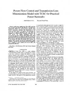
Fig. 6. DFIG losses for different d-axis currents. (a) Total losses[W]. (b) Magnetizing, rotor and stator d-axis currents [A].
(c)
y
0.40 0.20 0.00
λqs
-0.20
This current is constant regardless of the operating condition, which results from the assumption that the sharing of
-0.40 2.00
magnetizing current between i ds and i dr doesn’t influence the loss as mentioned above. Since this assumption makes some errors about 2 to 3% from the actual minimization, it can be called a quasi-minimization of the generator loss. With (27), the reactive power reference in (9) is given by
Qs* =
3 ⋅ vqs ids* 2
2.50
3.00 Rotor flux
Lamqr
Lamdr
λdr
(d)
y
0.40
0.20
λqr
0.00
-0.20
(29)
2.00
2.50
3.00
V. SIMULATION RESULTS To verify the developed algorithm, simulations carried out for a DFIG wind generation system using PSCAD software. The ratings and parameters of the DFIG are listed in Table I and the turbine parameters are listed in Table II. Fig. 6 shows power loss characteristics with regard to the stator d-axis current at 6[m/s] wind speed. In this wind speed, there is only one d-axis current value which gives a minimum power loss. The rotor d-axis current can be reduced from the rated value to reduce the total losses and thereby the system operating efficiency is increased. As the rotor d-axis current is decreased, the stator d-axis current increases and the total losses decrease as shown in Fig. 6 (b). Fig. 7(a) shows the generator performance at 5[m/s] wind speed. The DFIG starts with the zero reactive power reference, and then the loss minimization algorithm is activated at 3[sec] and remains activated. Both iron and copper losses decrease as the generator reactive power is set to the optimum value. The power loss is decreased from 1400[W] to 950[W], it means power saving of about 32% is obtained. In Fig. 7(b), the rotor d-axis current is decreased as the stator d-axis current increases. Since the stator fluxes are determined by the stator voltage and frequency, it remains constant even after activation of loss minimization, as shown in Fig. 7(c). The rotor fluxes change due to the current change as shown in Fig. 7(d). It is noticeable
(e)
(f)
Time [s]
Fig. 7 Loss minimization control at 5 m/s wind speed. (a) Generator loss [W]. (b) Stator and rotor d-axis currents [A]. (c) Stator fluxes [Wb]. (d) Rotor fluxes [Wb]. (e) Torque [p.u.]. (f) Speed [rpm].
that the torque and speed are constant due to complementary change of the d and q-axis currents as shown in Fig. 7 (e) and (f), respectively. Fig. 8 shows the results of loss minimization control at variable wind speed. During variable wind speed, the loss minimization control works well as shown in Fig. 8(b). The stator d-axis current in (c) oscillates slightly due to the stator qaxis current variation.
1112
Wind speed 10.0
9.0 8.0
y
7.0 6.0 5.0 4.0 0.00 3.5k
0.50
1.00
1.50
Total Loss
2.00 Total losses
2.50
Pcupper
3.00
3.50
4.00
Piron
3.0k 2.5k
y
2.0k
Fig. 10. Generator power variation (a) vs. rotor d-axis current (b).
1.5k 1.0k 0.5k 0.0 1.50
1.75
2.00
2.25
2.50
2.75
3.00
3.25
3.50
3.75
4.00
(a)
Idr Ids 500
Idrpe_
0 [W]
Ids
50 [W]/div
400
y
300 200
(b)
0 [A]
100
4 [A]/div
0 1.50
2.00
2.50
3.00
3.50
4.00
(c) 0 [VAR]
Power loss [W]]
Fig. 8. DFIG losses at variable wind speed. (a) Wind speed [m/s]. (b) Generator losses [W]. (c) Rotor, stator d-axis currents [A]. 9000 8000 7000 6000 5000 4000 3000 2000 1000 0
200 [VAR]/div
C onventio nalcontrol Lo ss m inim izatio n co ntrol
(d)
0 [A] 8 [A]/div
4
5
6
7
8
9
10
(e)
Wind speed [m/s]
0 [Nm]
Fig. 9. Comparison of power losses versus wind speed (simulation).
2 [Nm]/div 0.1 [s]/div
Fig. 11. Generator loss minimization at 5 m/s wind speed. (a) Total losses. (b) Rotor d-axis current. (c) Stator reactive power. (d) Stator d-axis current. (e) Generator torque.
Fig. 9 shows the comparison of power losses with regard to the wind speed. It is shown that the loss reduction is more significant at low wind speed. VI. EXPERIMENTAL RESULTS To verify the feasibility of the proposed control scheme, some experiments were performed for a 3[kW] laboratory prototype. The stator of the DFIG is connected to the utility grid. The rotor is connected to the grid through back-to-back PWM converters. The converter switching frequency is 5[kHz] and the sampling periods of the inner current and outer power control loops are 100 [µs ] , 1 [ms] , respectively. The ratings and parameters of the DFIG are listed in Table I and the turbine parameters are listed in Table II. Fig. 10 shows the effect of controlling the stator reactive power on the total generator loss. The generator loss decreases as the rotor d-axis current is reduced as shown in Fig. 10(a)
and (b). If the rotor d-axis current decreases further less than the optimum value, the generator loss increases accordingly. Fig. 11 shows the generator performance at 5[m/s] wind speed. The DFIG starts with the zero reactive power reference, and then the loss minimization algorithm is activated and remains active. As the generator reactive power is set to the optimum value, the total generator losses decrease to the optimum value as shown in Fig. 11(a). The power loss is decreased from 130[W] to 100[W], which means power saving of about 23% is obtained. The generator dynamic performance is investigated as shown in Fig. 11(e). It is noticeable that the torque is kept constant as the rotor d-axis current is decreased. Fig. 12 shows the generator performance at 7[m/s] wind speed, just the same as Fig. 11. The power loss is decreased
1113
from 148[W] to 121[W], where power saving about 22% is obtained. Fig. 13 shows the power loss versus the wind speed. The reduction of power loss is effective most of the wind speed range. However, its margin decreases at high wind speed. VII. CONCLUSIONS It is well known that wind generation system may operate at a fraction of the rated power most of the time. Reducing the generator losses is critical issue for reducing the cost of energy in such conditions. In this paper, a loss minimization algorithm for wind driven doubly-fed induction generator was proposed. The generator total losses are minimized through controlling the stator reactive power. To verify the effectiveness of the proposed algorithm, the simulations have been performed for a 2[MW] doubly-fed induction generator system. The simulation results have shown that it is possible to reduce the power loss up to 30% at 5[m/s] wind speed. The proposed algorithm proved validity to reduce the generator up to 23% at 5[m/s] using 3[kW] prototype. Fig. 12. Generator loss minimization at 7 m/s wind speed. (a) Total losses. (b) Rotor d-axis current. (c) Stator reactive power. (d) Stator daxis current.
APPENDIX TABLE I PARAMETERS OF DFIG
300
Values 2[MW] 690[V] 0.0048[p.u] 0.00549[p.u] 0.018[p.u] 0.09241[p.u] 0.09955[p.u] 3.95279[p.u] 4800[kg ㎡]
Power loss [W]]
Parameters Rated Power Rated Line voltage Stator resistance Rotor resistance Iron loss resistance Stator leakage inductance Rotor leakage inductance Mutual inductance Moment of inertia
3[kW] 220[V] 0.6[Ω] 0.713[Ω] 155[Ω] 0.003313[H] 0.003313[H] 0.063443[H] 0.051[kg ㎡]
100
4
5
6
7
8
9
10
Wind speed [m/s]
Fig. 13. Comparison of power losses versus wind speed.
Values 2[MW] 3[kW] 40[m] 0.95[m] 0.45 0.45 7 7 4[m /s] 4[m /s] 12[m /s] 13[m /s] 80 2
This work has been supported by the KEMCO (Korea Energy Management Corporation) under project grant (2004N-WD12-P-06-3-010-2006). REFERENCES
[2]
150
0
ACKNOWLEDGMENT
[1]
Loss minimozation control
200
50
TABLE II PARAMETERS OF TURBINE BLADE MODEL
Parameters Rated Power Blade radius Max. power conv. coeff. Optimal tip-speed ratio Cut-in speed Rated wind speed Gear ratio
Conventional control
250
Q. Wang and L. Chang, ” An intelligent maximum power extraction algorithm for inverter-based variable speed wind turbine systems,” IEEE Trans. Power Electron., vol. 19, No. 5, pp. 1242 – 1249, Sept. 2004. F. F. M. El-Sousy, M. Orabi, and H. Godah, “Maximum power point tracking control scheme for grid connected variable speed wind driven
self-excited induction generator,” KIPE Journal of Power Electron., vol. 6, no. 1, pp.45-51, Jan. 2006. [3] H. Akagi and H. Sato, “Control and performance of a doubly-fed induction machine intended for a flywheel energy storage system,” IEEE Trans. on Power Electron., vol. 17, no. 1, pp. 109–116, Jan. 2002. [4] M. Yamamoto and O. Motoyoshi, “Active and reactive power control for doubly-fed wound rotor induction generator,” IEEE Trans. on Power Electron., vol. 6, no. 4, pp. 624–629, Oct. 1991. [5] R. Pena, J. C. Clare, and G. M. Asher, “Double fed induction generator using back-to-back PWM converter and its application to variable- speed wind-energy generation,” IEE Proc. , vol. 143, no. 3, pp. 231–241, 1996. [6] A. Tapia, G. Tapia, J. X. Ostolaza, and J. R. Saenz, “Modeling and control of a wind turbine driven doubly-fed induction generator,” IEEE Trans. Energy Conv., vol. 18, no. 2, pp. 149–204, June 2003. [7] L. Xu and Y. Tang,” A flexible active and reactive power control strategy for a variable speed constant frequency generating system,” IEEE Trans. on Power Elctron., vol. 10, no.4, pp. 472 - 478, July, 1995. [8] B. Rabelo, W. Hofmann, and L. Pinheiro, “Loss reduction methods for doubly-fed induction generator drives for wind turbines,” IEEE SPEEDAM Conf. Proc., vol. 3, 2006, pp.16-21. [9] W. Hofmann and F. Okafor, “Optimal control doubly fed full controlled induction wind generator with high efficiency,” IEEE IECON Conf. Proc., vol. 2, 2001, pp.123-1218. [10] S-D. Wee, M-H. Shin, and D-S. Hyun, “Stator-flux-oriented control of induction motor considering iron loss,” IEEE Trans. on Ind. Elctron., vol. 48, no.3, pp. 472 - 478, June, 2001. [11] Ahmed G. Abo-Khalil, Dong-Choon Lee, and Se-Hyun Lee, “Grid connection of doubly-fed induction generators in wind energy conversion system,” IPEMC, Shanghai, vol. 3, 2006, pp. 1487-1491.
1114