micromachines Article
Love-Mode MEMS Devices for Sensing Applications in Liquids Cinzia Caliendo 1, *, Smail Sait 2,3 and Fouad Boubenider 2 Received: 28 October 2015; Accepted: 14 January 2016; Published: 21 January 2016 Academic Editor: Nathan Jackson 1 2
3
*
Istituto di Acustica e Sensoristica “O.M. Corbino”, IDASC, Consiglio Nazionale delle Ricerche, CNR, Via del Fosso del Cavaliere 100, 00133 Rome, Italy Laboratory of Physics of Materials, Team “Waves and Acoustic”, University of Sciences and Technology, Houari Boumedienne, B.P. 32 El Allia, Bab-Ezzouar, 16111 Algiers, Algeria;
[email protected] (S.S.);
[email protected] (F.B.) Faculté des Sciences, Université M. Mammeri, BP 17 R.P., 15000 Tizi-Ouzou, Algeria Correspondence:
[email protected]; Tel.: +39-06-49934071; Fax: +39-06-45488061
Abstract: Love-wave-based MEMS devices are theoretically investigated in their potential role as a promising technological platform for the development of acoustic-wave-based sensors for liquid environments. Both single- and bi-layered structures have been investigated and the velocity dispersion curves were calculated for different layer thicknesses, crystallographic orientations, material types and electrical boundary conditions. High velocity materials have been investigated too, enabling device miniaturization, power consumption reduction and integration with the conditioning electronic circuits. The electroacoustic coupling coefficient dispersion curves of the first four Love modes are calculated for four dispersive coupling configurations based on a c-axis tilted ZnO layer on wz-BN substrate. The gravimetric sensitivity of four Love modes travelling at a common velocity of 9318 m/s along different layer thicknesses, and of three Love modes travelling at different velocity along a fixed ZnO layer thickness, are calculated in order to design enhanced-performance sensors. The phase velocity shift and attenuation due to the presence of a viscous liquid contacting the device surface are calculated for different thicknesses of a c-axis inclined ZnO layer onto BN half-space. Keywords: microsensors; acoustic modes; piezoelectric materials
1. Introduction Chemical sensors based on the propagation of surface acoustic waves (SAWs) are usually based on a delay line or resonator configuration with the acoustic wave path covered by a membrane sensible to a specific target analyte. When the specific target molecule interacts with the membrane, such as antibody and microorganism, the membrane changes its mechanical properties, thus affecting the phase velocity and/or propagation loss of the wave. As a consequence, the device resonance frequency and/or attenuation changes can be used to quantify the sensors response. The performances of the electroacoustic sensors are affected by the behaviour of the thin membrane as well as by the device design. The membrane is required to be reversible, repeatable, stable in time and selective. The electroacoustic device to be used for sensing applications in liquid environment must involve the propagation of in-plane polarized modes since these modes do not radiate energy into the liquid. In this context, Love wave surface modes are promising platforms for biosensing applications. The Love wave is a shear horizontally (SH) polarized wave that propagates on the surface of a piezoelectric half-space or of a thin piezoelectric layer deposited on a semi-infinite substrate. The SH polarization ensures a weak acoustic energy loss in the liquid phase contacting the device surface, while the latter ensures a strong energy confinement in the piezoelectric layer. Love wave sensors have been attracting Micromachines 2016, 7, 15; doi:10.3390/mi7010015
www.mdpi.com/journal/micromachines
Micromachines 2016, 7, 15
2 of 13
the interest of many researchers since the early 1990s [1–3] due to their remarkable features: the lower Micromachines 2016, 7, 15 2 of 12 acoustic wave velocity of the layer results in the acoustic wave being guided through the layer itself, resulting in minimal acoustic losses into the bulk of the substrate or into the liquid contacting the device surface, while the latter ensures a strong energy confinement in the piezoelectric layer. Love sensor surface. Moreover, performances can be achieved choosing a proper wave sensors have beenimproved attracting sensor the interest of many researchers since the by early 1990s [1–3] due to layer thickness, which increases the sensitivity of the device towards changes in physical properties their remarkable features: the lower acoustic wave velocity of the layer results in the acoustic wave at its surface, including mass loading. being guided through the layer itself, resulting in minimal acoustic losses into the bulk of the substrate or into the liquid contacting the sensor surface. Moreover, sensor In this study, we theoretically studied the propagation of Loveimproved wave along theperformances surface of some can be achieved by choosing a proper layer thickness, which increases the sensitivity of the device piezoelectric substrates (AlN, InN, ZnO, GaN, ST quartz): the phase velocity and the electroacoustic 2 towards changes in physical properties at its surface, including mass loading. coupling coefficient (K ) were calculated for different c-axis tilt angles with respect to the surface In this study, we theoretically studied the propagation2of Love wave along the surface of some normal. In order to increase the Love wave velocity and K with respect to those obtained for single piezoelectric substrates (AlN, InN, ZnO, GaN, ST quartz): the phase velocity and the electroacoustic material substrates, we investigated a dispersive structure consisting in a thin piezoelectric ZnO coupling coefficient (K2) were calculated for different c-axis tilt angles with respect to the surface layernormal. on top In of order the surface of a semi-infinite BN substrate. The ZnO layer has its c-axis inclined onto to increase the Love wave velocity and K2 with respect to those obtained for single 2 and velocity dispersion the surface while the BN has its c-axis normal to the free surface. material substrates, we investigated a dispersive structure consistingThe in aKthin piezoelectric ZnO curves, and sensitivities were calculated forThe different Love modes, in inclined order toonto compare layer onthe topgravimetric of the surface of a semi-infinite BN substrate. ZnO layer has its c-axis 2 and velocity the overall behavior of the based on different Love modes. the first Love mode the surface while the BN sensors has its c-axis normal to the free surface. The KFinally, dispersion curves, and and relative the gravimetric were Love modes, in order attenuation velocitysensitivities shift due to thecalculated presence for of adifferent liquid (water) contacting the to device compare the overall behavior of the sensors based on different Love modes. Finally, the first surface were calculated for different ZnO layer thicknesses, thus confirming that the sensorLove behavior mode attenuation and relative shift due to the presence of a liquid (water) contacting can be enhanced by proper choicevelocity of material parameters (i.e., types and thicknesses) of the the layered device surface were calculated for different ZnO layer thicknesses, thus confirming that the sensor waveguide structure. behavior can be enhanced by proper choice of material parameters (i.e., types and thicknesses) of the layered waveguide structure. 2. Love Wave Propagating Along a Piezoelectric Half-Space
2. Love Wave Propagating Piezoelectric The propagation of the Along Love awave can be Half-Space excited and detected by means of interdigitated transducers as well forLove the SAWs. Referring to aand coordinate with x1 and x3 parallel The(IDTs), propagation ofas the wave can be excited detected system by means of interdigitated to thetransducers wave propagation direction and normal to the substrate surface, respectively, electrically (IDTs), as well as for the SAWs. Referring to a coordinate system with x1 andthe x3 parallel coupled Love wave requires direction the piezoelectric constants e16 and, or e36 to respectively, be different from zero. A (0002) to the wave propagation and normal to the substrate surface, the electrically coupled Love wavematerial requiresof the piezoelectric e16 and, or e36has to be from zero. A oriented piezoelectric the hexagonalconstants system (class 6 mm) nodifferent piezoelectric coefficients (0002) oriented material the hexagonalofsystem (class 6can mm) no piezoelectric that couple to shearpiezoelectric deformation, henceof the excitation shear waves behas obtained by tilting the that to shear deformation, hence excitation of shear c-axiscoefficients orientation bycouple an angle µ from the normal, as the shown in Figure 1. waves can be obtained by tilting the c axis orientation by an angle μ from the normal, as shown in Figure 1. As a result, the electric field is coupled only with the particle motion in the shear horizontal As a result, the electric field is coupled only with the particle motion in the shear horizontal (SH) direction, U2 . U2 is maximum at the free surface of the substrate and remains constant for (SH) direction, U2. U2 is maximum at the free surface of the substrate and remains constant for about aboutone onewavelength wavelength in depth, and then it decreases asymptotically. Therefore the electroacoustic in depth, and then it decreases asymptotically. Therefore the electroacoustic coupling coefficient is affected byby the anglefrom fromthe the vertical as well asthe bywave the wave coupling coefficient is affected thec-axis c-axisinclination inclination angle vertical as well as by 2 propagation direction. The phase K2 of ofthe theLove Lovewave wave travelling along the surface propagation direction. The phasevelocity velocity and and K travelling along the surface of of somesome piezoelectric substrates were calculated by using Matlaba routine the lossless approximation; piezoelectric substrates were calculated by ausing Matlab inroutine in the lossless approximation; the material (mass density, elastic, and dielectric constants)toare the material data (mass density,data elastic, piezoelectric, andpiezoelectric, dielectric constants) are referred in [4,5]. referred to in [4,5]. By tilting the c-axis of the AlN, InN, ZnO and GaN piezoelectric half-spaces with By tilting the c-axis of the AlN, InN, ZnO and GaN piezoelectric half-spaces with respect to the surface respect the surface normal, phase velocity of theasLove changes, as well as the coupling normal, the to phase velocity of thethe Love wave changes, wellwave as the coupling coefficient, as shown in coefficient, as shown in Figures 2 and 3. Figures 2 and 3.
Figure laboratory coordinate coordinate system system (x thethe propagating medium Figure 1. 1. TheThelaboratory (x11, , x2x2and andx3)x3and ) and propagating medium crystallographic axis (x, −y and z ≡ c); μ is the c-axis tilt angle respect to x3. crystallographic axis (x, ´y and z ” c); µ is the c-axis tilt angle respect to x3 .
Micromachines 2016, 7, 15 Micromachines Micromachines 2016, 2016, 7, 7, 15 15
3 of 13 33 of of 12 12
Figure Figure 2. 2. The The phase phase velocity velocity of of the the Love Love wave wave travelling travelling along along the the xx propagation propagation direction direction of of AlN, AlN, travelling along the propagation direction of AlN, GaN, InN and ZnO substrates vs. the c-axis tilt angle. GaN, InN and ZnO substrates vs. the c-axis tilt angle.
2 Figure Figure 3. 3. The The K K2 of of the the Love Love wave wave travelling travelling along along the the xx propagation propagation direction direction of of AlN, AlN, GaN, GaN, InN InN and and Figure 3. The K2 of the Love wave travelling along the x propagation direction of AlN, GaN, InN and ZnO substrates vs. the c-axis tilt angle. ZnO substrates vs. the c-axis tilt angle. ZnO substrates vs. the c-axis tilt angle.
A A piezoelectric piezoelectric material material widely widely used used for for the the implementation implementation of of Love Love wave wave based based sensors sensors [6–9] [6–9] A piezoelectric material widely used for the implementation of Love wave based sensors is is the ST-Y quartz where the wave propagation direction is orthogonal to the crystalline X is the ST-Y quartz where the wave propagation direction is orthogonal to the crystalline [6–9] X axis axis the ST-Y quartz where the wave propagation direction is orthogonal to the crystalline x axis direction direction in order to allow the excitation of purely shear polarized modes by means of the IDTs: direction in order to allow the excitation of purely shear polarized modes by means of the IDTs: 2 in order the excitation of purely shear polarized by means of coupling the IDTs: of 4991 m/s is the 4991 m/s the velocity 0.018% is K weak this material 4991 m/stois isallow the wave wave velocity and and 0.018% is the the K2.. The Themodes weak piezoelectric piezoelectric coupling of this material 2 wave velocity and 0.018% is the K . The weak piezoelectric coupling of this material be improved can be improved by covering the free surface of the quartz substrate with a thin SiO 2 can layer. This layer can be improved by covering the free surface of the quartz substrate with a thin SiO2 layer. This layer by covering the freerole surface of the quartz substrate with a thin SiO2 layer. This layer plays the twofold plays the of the electroacoustic coupling coefficient, while trapping the plays the twofold twofold role of increasing increasing the electroacoustic coupling coefficient, while trapping the role of increasing the electroacoustic coupling coefficient, while trapping the acoustic energy near the acoustic energy near the surface of the substrate. Figure 4 shows the particle displacement acoustic energy near the surface of the substrate. Figure 4 shows the particle displacement surface surface of the substrate. Figure 4 shows the particle displacement component normalized to its surface component normalized to value, U ,, vs. of 2/quartz propagating component normalized to its its surface surface value, U22/U /U22surface vs. the the depth depth of the the SiO SiO 2/quartz propagating surface , vs. the depth of the SiO /quartz propagating medium; the running parameter is value, U /U medium; medium;2 the the2 running running parameter parameter is is the SiO SiO222 film film thickness thickness normalized normalized to to the acoustic acoustic wavelength wavelength the SiO film thickness normalized to the acoustic wavelength (h /λ). The abscissa of the (h SiO2 /λ). The abscissa of the graph has been normalized to h SiO2 to make visible the layer 2 SiO2 (hSiO2/λ). The abscissa of the graph has been normalized to hSiO2 to make visible how how thegraph layer has been normalized to h to make visible how the layer thickness affects the acoustic field at the thickness affects the acoustic field at the layer/substrate interface (depth/h SiO2 equal to 1) and inside SiO2 field at the layer/substrate interface (depth/hSiO2 equal to 1) and inside thickness affects the acoustic layer/substrate interface (depth/h equal to 1) and inside substrate. With increasing layer layer thickness, more and more energy inside the the increasing SiO layer thickness, more andthe more energy is is trapped trapped insideSiO the2 layer layer the substrate. substrate. With With increasing SiO22SiO2 thickness, more and more energy is trapped inside the layer and, for h /λ > 0.07, the displacement and, for h SiO2 /λ > 0.07, the displacement component value at the quartz surface starts becoming SiO2 and, for hSiO2/λ > 0.07, the displacement component value at the quartz surface starts becoming ever ever component at the equal quartzto starts everAs lower, while in it to 1aaatfew, the lower, it 11 at layer free described [7,10], cite lower, while whilevalue it remains remains equal tosurface at the the layerbecoming free surface. surface. As described inremains [7,10], to toequal cite just just few, layer free surface. As described inmass [7,10],sensitivity to cite just few, the SiO layer thickness the mass the 2 layer thickness affects the ofathe sensor to the viscous liquidaffects characteristics, the SiO SiO 2 layer thickness affects the mass sensitivity of the sensor to 2the viscous liquid characteristics, sensitivity of the sensor to the viscous liquid characteristics, as well as the insertion loss, temperature as well as the insertion loss, temperature coefficient of oscillation frequency and frequency noise. as well as the insertion loss, temperature coefficient of oscillation frequency and frequency noise. coefficient of oscillation frequency and frequency noise.
Micromachines 2016, 7, 15 Micromachines 2016, 7, 15 Micromachines 2016, 7, 15
4 of 13 4 of 12 4 of 12
Figure 4. The The normalized normalized particle particle displacement displacement component Love wave wave vs. vs. the acoustic wave wave Figure 4. component of of the the Love the acoustic Figure 4. The normalized particle displacement component of the Love wave vs. the acoustic wave penetration depth normalized to the SiO 2 layer thickness hSiO2; the SiO2 thickness to wavelength ratio, penetration depth normalized to the SiO2 layer thickness hSiO2 ; the SiO2 thickness to wavelength ratio, penetration depth normalized to the SiO2 layer thickness hSiO2; the SiO2 thickness to wavelength ratio, hhSiO2/λ, /λ,isisthe therunning runningparameter. parameter. hSiO2 SiO2/λ, is the running parameter.
The presence of the SiO2 layer affects the acoustic field distribution as well as the K22 of the The presence of the SiO field distribution as well as the K SiO22 layer affects the acoustic K2 of the SiO2/ST-quartz substrate, as shown in Figure 5. The K22 improves with increasing layer thickness up 2 SiO2/ST-quartz /ST-quartzsubstrate, substrate,as asshown shown in in Figure Figure 5. 5. The The K improves improves with with increasing increasing layer thickness up to the threshold value hSiO2/λ = 0.07, while it decreases for higher layer thicknesses. The velocity as to the threshold /λ = 0.07, while it decreases for higher layer thicknesses. velocity value h SiO2 /λ = 0.07, while it decreases for higher layer thicknesses. TheThe velocity as well as the K2 values of SiO2 the SiO2/quartz substrate are much lower than those referred to the c-axis 2 values 2 as well as the K of the SiO /quartz substrate are much lower than those referred to the well as the K values of the SiO2/quartz substrate are much lower than those referred to the c-axis inclined AlN, while only the K2 of the22 GaN, InN and ZnO bare substrates is competitive with that of c-axis inclined AlN, only whilethe only K GaN, of theInN GaN, InN andbare ZnO bare substrates is competitive with inclined AlN, while K2 the of the and ZnO substrates is competitive with that of the SiO2/quartz substrate. Among these materials, AlN is the fastest while ZnO ensures the highest that of the SiO /quartz substrate. Among these materials, AlN is the fastest while ZnO ensures the SiO2/quartz2substrate. Among these materials, AlN is the fastest while ZnO ensures the highest K2 value. Moreover, these piezoelectric materials can be grown in thick film form onto the K2 value. Moreover, these piezoelectric materials be grown in thick filmform form onto K2 highest value. Moreover, these piezoelectric materials can becangrown in thick film non-piezoelectric substrates, such as silicon, and, provided that their thickness is greater than the non-piezoelectric substrates, substrates, such such as silicon, and, provided that their thickness is greater than the acoustic wavelength, are suitable for the implementation of Love-wave-based sensor platforms for acoustic wavelength, are suitable for the implementation of Love-wave-based Love-wave-based sensor platforms for applications in liquid environments. applications in liquid environments. environments.
Figure 5. The K2 of the ST-Y quartz vs. the SiO2 normalized thickness. Figure 5. 5. The The K K22 of quartz vs. vs. the SiO2 normalized thickness. Figure of the the ST-Y ST-Y quartz the SiO 2 normalized thickness.
3. Love Modes Propagating Along a Piezoelectric Layer onto a Non Piezoelectric Half-Space 3. Love Modes Propagating Along a Piezoelectric Layer onto a Non Piezoelectric Half-Space 3. Love Modes Propagating Along a Piezoelectric Layer onto a Non Piezoelectric Half-Space Dispersive Love wave devices can also be developed which consist of a thin wave guide layer Dispersive Love wave devices can also be developed which consist of a thin wave guide layer on top of the surface of a substrate. The essential condition forconsist the propagation of the Love wave Dispersive Love wave devices can also be developed which of a thin wave guide layer on on top of the surface of a substrate. The essential condition for the propagation of the Love wave along layered medium is that the bulkcondition wave velocity in the layer is smaller than top of athe surface of a substrate. Theshear essential for the(SHBAW) propagation of the Love wave along along a layered medium is that the shear bulk wave velocity (SHBAW) in the layer is smaller than that in themedium substrate, i.e., the the substrate. a result,inmultiple modesthan propagate a layered is that the layer shearloads bulk wave velocity As (SHBAW) the layerLove is smaller that in that in the substrate, i.e., the layer loads the substrate. As a result, multiple Love modes propagate which involvei.e., only displacements perpendicular toathe sagittal plane.Love The modes phase velocity vph which of the the substrate, the layer loads the substrate. As result, multiple propagate which involve only displacements perpendicular to the sagittal plane. The phase velocity vph of the first mode becomes equal to the SHBAW velocity of the substrate with decreasing layer thickness, first mode becomes equal to the SHBAW velocity of the substrate with decreasing layer thickness, while it asymptotically reaches the SHBAW velocity of the layer with increasing layer thickness. The while it asymptotically reaches the SHBAW velocity of the layer with increasing layer thickness. The
Micromachines 2016, 7, 15
5 of 13
involve only displacements perpendicular to the sagittal plane. The phase velocity v ph of the first mode becomes equal to the SHBAW velocity of the substrate with decreasing layer thickness, while it Micromachines 2016,reaches 7, 15 5 of 12 asymptotically the SHBAW velocity of the layer with increasing layer thickness. The higher order Love modes have a cut off when their v ph equals the SHBAW velocity of the substrate and at the higher Lovevelocity modes have a cut voff .when their vph equals the SHBAW velocity of the substrate cut off order the group vgr equals ph Unlike the v ph , the v gr dispersion curve of each mode has and at the cut voff and the group velocity vgr equals vph.the Unlike the vvelocity ph, the vgr dispersion curve of each infinite slope. vgr approach asymptotically SHBAW of the layer with increasing ph mode has infinite slope. v ph and vgr approach asymptotically the SHBAW velocity of the layer with the layer thickness, as illustrated by the dispersion curves in Figure 6 for a c-axis inclined ZnO film on increasing the layer thickness, as illustrated the dispersion curves in Figure 6 for a c-axis inclined a semi-infinite wurtzite BN substrate. The vby gr was calculated from the v ph by the following formula: » fi ZnO film on a semi-infinite wurtzite BN substrate. The vgr was calculated from the vph by the — dv ph ffi h following formula: 1 + λ the acoustic , being λ the acoustic wavelength and hInthe layer ˆ =˙ ffi v gr “ v ph — , being wavelength and h the layer thickness. Figure 6, –1 ` λv h fl ph d the velocities of the SHBAW of the wz-BN and of the c-axis inclined ZnO are thickness. In Figure 6, λ shown as well.ofMany authors of have of theZnO growth ZnO layers with an the velocities the SHBAW thedemonstrated wz-BN and ofthe thefeasibility c-axis inclined are of shown as well. Many in-plane c-axisdemonstrated onto differentthe substrates, such as on R plane [11,12], Au/SiOc-axis 2 substrate authors have feasibility of the growth of sapphire ZnO layers with onto an in-plane onto [13], ontosubstrates, Au [14] onsuch an indium oxide (ITO)[11,12], on quartz and on Al onto polycrystalline different as on R tin plane sapphire ontosubstrate Au/SiO2[15], substrate [13], Au [14] on films [16], to a on few. wz-BN films are grown by sputtering and an indium tinname oxide just (ITO) quartz substrate [15],currently and on Al polycrystalline films(DC [16],or to RF) name justbya hollow cathode apparatus on Si(001) and respectively and chemical few. wz-BN filmsarc are evaporation currently grown by sputtering (DC or RF)Si(111), and by hollow cathode arcby evaporation vapor deposition: at and the Si(111), present,respectively the growthand of BN presents vapor a viable route towards large-scale apparatus on Si(001) by chemical deposition: at the present, the manufacturing of BN substrates [17–20]. Thus, the feasibility of the proposed ZnO c-axis growth of BN presents a viable route towards large-scale manufacturing of BN substrates [17–20]. inclined/wz-BN acoustic is reliable and compatible with semiconductor processing Thus, the feasibility of the waveguide proposed ZnO c-axis inclined/wz-BN acoustic waveguide is reliable and techniques, provided that the BN thicknesstechniques, is greater than the acoustic Such multilayer compatible with semiconductor processing provided that thewavelength. BN thickness is greater than structure offers the advantage providingstructure the monolithic integration of of the device with the signal the acoustic wavelength. Suchof multilayer offers the advantage providing the monolithic processing Other of materials can be explored also to improve the thermal integrationelectronics. of the device withcombinations the signal processing electronics. Other combinations of materials can stability (byalso choosing materials with temperature coefficient delay opposite in sign) coefficient [21] and be explored to improve the thermal stability (by choosing materials with temperature resistance to harsh environments (choosing materials able to survive at high temperatures and in delay opposite in sign) [21] and resistance to harsh environments (choosing materials able to survive chemically aggressiveand environments). at high temperatures in chemically aggressive environments).
Figure 6. The phase and group velocity dispersion curves of the Love modes travelling along the x Figure 6. The phase and group velocity dispersion curves of the Love modes travelling along the x propagation of c-axis c-axis inclined inclined ZnO/wz-BN. ZnO/wz-BN. propagation direction direction of
In designing a Love wave device, an important feature to be obtained is low insertion loss, In designing a Love wave device, an important feature to be obtained is low insertion loss, which can be achieved by selecting a material with a large K2.2The value of K2 is2 directly related to which can be achieved by selecting a material with a large K . The value of K is directly related the IDT electrical-to-mechanical energy conversion efficiency; hence, it determines the radiation to the IDT electrical-to-mechanical energy conversion efficiency; hence, it determines the radiation resistance of the transducer that is fabricated on the substrate and the piezoelectric guiding layer. resistance of the transducer that is fabricated on the substrate and the piezoelectric guiding layer. The The layer/substrate combination allows the implementation of four different coupling layer/substrate combination allows the implementation of four different coupling configurations, configurations, shown in Figure 7, with the IDTs placed on one of the ZnO layer surfaces, with or shown in Figure 7, with the IDTs placed on one of the ZnO layer surfaces, with or without a floating without a floating electrode on the opposite one. The configuration called substrate/film/transducer electrode on the opposite one. The configuration called substrate/film/transducer (SFT) refers to a (SFT) refers to a coupling structure with the IDTs positioned on the ZnO free surface: when a floating metallic plane (M, metal) is placed at the ZnO/BN interface, the configuration is called SMFT. The configuration called substrate/transducer/film (STF) refers to a coupling structure with the IDTs positioned at the ZnO/BN interface: when the metallic plane is positioned at the ZnO free surface, the configuration is called STFM.
Micromachines 2016, 7, 15
6 of 13
coupling structure with the IDTs positioned on the ZnO free surface: when a floating metallic plane (M, metal) is placed at the ZnO/BN interface, the configuration is called SMFT. The configuration called substrate/transducer/film (STF) refers to a coupling structure with the IDTs positioned at the ZnO/BN interface: when the metallic plane is positioned at the ZnO free surface, the configuration is Micromachines 2016, 7, 15 6 of 12 called STFM.
Figure 7. The four different coupling configurations. Figure 7. The four different coupling configurations.
For SAWs the K2 can be defined in terms of the piezoelectric coefficient, elastic constants and For SAWs the K2 K can defined in terms the piezoelectric coefficient, elasticvalues constants and 2 = be dielectric permittivity, e2/cε, being the tensorofsubscripts dropped: the appropriate of these 2 2 dielectric permittivity, K =crystallographic e /cε, being the orientation tensor subscripts the appropriate values of these constants depend on the of thedropped: piezoelectric material [22]. A simpler constants depend on the crystallographic orientation of the piezoelectric material [22]. A simpler method for calculating the efficiency of excitation of acoustic surface waves by means of interdigital method for calculating theon efficiency of excitation of acoustic surfacechange waves due by means of interdigital transducers [23] is based the calculation of the wave velocity to a change in the transducers [23] is based on the calculation of the wave velocity change due to a change in the film electric electric field boundary conditions. When a thin, massless, perfectly conducting metal is field boundary a thin, massless, metal film is deposited deposited on theconditions. surface of When a piezoelectric layer, theperfectly potentialconducting and the longitudinal electric field on at the piezoelectric surface of a piezoelectric the potential and the longitudinal electric field at thewhich piezoelectric the surface layerlayer, are zero, and the wave velocity is reduced by an amount can be surface layer are zero, and the wave velocity is reduced by an amount which can be regarded as a regarded as a measure for the coupling strength between the wave and the metal surface electrode. measure for the coupling strength between the wave and the metal surface electrode. The higher the The higher the velocity change, the higher the coupling to an electrode grating transducer which velocity change, the coupling an electrode grating transducer responds mainly responds mainlythe to higher the tangential field.to For piezoelectric materials withwhich a weak piezoelectric to the tangential field. For piezoelectric materials with a weak piezoelectric coupling coefficient, coupling coefficient, this quantity can be written to a good approximation [24] as K2 ≈ 2·Δv/vf = 2·(vf − quantity can be written to a good approximation [24] as K2 « 2¨ ∆v/v = 2¨ (v f ´ZnO vm )/v f , where vthis m)/vf, where vm and vf are the velocities calculated in the metalized fand free boundary v and v are the velocities calculated in the metalized and free ZnO boundary condition. m f condition. For the layered structures depicted in Figure 7, the IDTs and the metal plane For can the be layered structures depicted in Figure 7, the IDTs and the metal plane can be positioned onto one of the positioned onto one of the two surfaces of the layer, thus the effects of four different electrical two surfaces of the layer, thusZnO the effects of four different electrical in boundary conditions thephase ZnO boundary conditions at the interfaces must be considered the calculation of at the 2 . By denoting interfaces must be considered in the calculation of the phase velocity and hence of the K velocity and hence of the K2. By denoting as vij (for i, j = m, f) the wave velocity referred to the as vij (for boundary i, j = m, f ) the wave velocity to the electrical conditions ofapproximated the lower and electrical conditions of the referred lower and upper layer boundary surface, the following upper layer surface, followingthe approximated formulas were used to calculate the coupling constant formulas were used the to calculate coupling constant of the four structures: of the four structures: ”´ ¯ ı 2 − KSFT “ = 2¨ 2 ∙ v f f ´ v f m {v f f ”´ ¯ ı 2 KSTF “ 2¨ v f f − ´ vm f {v f f = 2 ∙ ”´ ¯ ı 2 KSMFT “ 2¨ vm f ´ vmm {vm f − ¯ ı = 2 ∙ ”´ 2 KSTFM “ 2¨ v f m ´ vmm {v f m − The K2 dispersion curves were theoretically = 2 ∙ calculated for the first four Love modes propagating in the four different coupling structures, as shown in Figure 8. The mechanical effect of the metallization was The ignored the metallization is assumed to be infinitely thin. be seen 8, dispersion curves were theoretically calculated for As thecanfirst four from LoveFigure modes K2 as the Love modes along the dispersive highly8.sensitive to the electrical The mechanical effect of propagating in thepropagating four different coupling structures,structure as shownare in Figure boundary conditions. the metallization was ignored as the metallization is assumed to be infinitely thin. As can be seen from Figure 8, the Love modes propagating along the dispersive structure are highly sensitive to the electrical boundary conditions. With increasing the Love mode order, ever decreasing K2 values can be reached by the four coupling configurations: the SMFT of the first mode reaches the highest K2 value since the metallization on the ZnO side opposite the IDTs strongly enhances the vertical electric field in the
Micromachines 2016, 7, 15
7 of 13
With increasing the Love mode order, ever decreasing K2 values can be reached by the four coupling configurations: the SMFT of the first mode reaches the highest K2 value since the metallization on the ZnO side opposite the IDTs strongly enhances the vertical electric field in the ZnO layer. Figure 92016, shows at Micromachines 2016, 7, 15 15 the displacement component profile for the first four Love modes travelling of 12 12 Micromachines 7, 77 of a common velocity of 9318 m/s along different ZnO layer thicknesses (h/λ = 0.050, 0.209, 0.369 and 0.528,respectively). respectively). As As can can be be seen, seen, the the displacement displacement in in the the ZnO ZnO layer varies sinusoidally while the 0.528, ZnO layer layer varies variessinusoidally sinusoidallywhile whilethe the 0.528, respectively). As can be seen, displacementin inthe theBN BNsubstrate substrate has has aa simple simple exponential decay with depth below the interface for displacement decay with with depth depthbelow belowthe theinterface interfacefor for displacement in the BN substrate has exponential decay all the modes. The slope of the curve of the displacement amplitude vs. depth is zero at the free all amplitude vs. vs. depth depthisiszero zeroatatthe thefree free allthe themodes. modes. The The slope slope of of the the curve curve of the displacement displacement amplitude interfacefor forallall all Love modes. Every Love mode is suitable suitable for liquid liquid sensing applications as the the interface Love modes. Every Love mode is suitable for liquid sensing applications as the particle interface for Love modes. Every Love mode is for sensing applications as particle displacement displacement component is at at the the maximum maximum at surface the free free that surface that contacts contacts the liquid. liquid. displacement component is at the maximum at the free contacts the liquid. particle component is at the surface that the
2 dispersion curves of the four coupling configurations calculated for the first four Figure8.8. 8.The TheKK 2K2dispersion Figure The dispersioncurves curves four coupling configurations calculated for first the first Figure ofof thethe four coupling configurations calculated for the four four Love Love modes propagating along 90° tilted ZnO film onto BN substrate. ˝ Love modes propagating along 90° tilted ZnO film onto BN substrate. modes propagating along 90 tilted ZnO film onto BN substrate.
Figure Theparticle particle displacement component thefour firstLove fourmodes Love travelling modes travelling at a Figure 9. 9. The The displacement component of the theoffirst first at aa common common Figure 9. particle displacement component of four Love modes travelling at common of m/sdifferent along different ZnO layer thicknesses (h/λ =0.209, 0.050,0.369 0.209,and 0.369 and velocity velocity of 9318 9318 m/s m/s9318 along ZnO layer layer thicknesses (h/λ == 0.050, 0.050, 0.528, velocity of along different ZnO thicknesses (h/λ 0.209, 0.369 and 0.528, 0.528, respectively). respectively). respectively).
4. Love-Mode Love-Mode Sensors Sensors 4. 4.1. Gravimetric Gravimetric Sensitivity Sensitivity 4.1. The gravimetric gravimetric sensitivity sensitivity S S of of the the Love Love waves waves sensor sensor was was theoretically theoretically estimated estimated by by The
Micromachines 2016, 7, 15
8 of 13
4. Love-Mode Sensors 4.1. Gravimetric Sensitivity The gravimetric sensitivity S of the Love waves sensor was theoretically estimated by calculating the velocity change that the modes undergo when the free ZnO layer surface is covered by a mass m = ρm ¨ hm , being ρm and hm the added mass density and thickness. The S of the Love modes travelling at equal-velocity (v = 9318 m/s) along different ZnO film thickness values was calculated as S = (∆v/v)/m, with ∆v = v’´ v, v and v’ the mode velocity along the mass-covered and bare surface. Table 1 lists the mode order, the layer thickness, the theoretically estimated S and the slope of the dv ph phase velocity dispersion curve, , evaluated at the corresponding ZnO layer thickness. With dph{λq increasing mode order, S drastically decreases and the linear behavior of the relative velocity change vs. the added mass is restricted to smaller hm values, as shown in Table 1. The highest S value correspond to the largest slope value; the decreasing values of sensitivity correspond to decreasing values of the slope. This fact confirm that the optimized sensor sensitivity corresponds to strong velocity dispersion. The gravimetric sensitivity of the Love modes travelling along equal ZnO layer normalized thickness (h/λ = 0.3) was theoretically predicted and the calculated sensitivities are listed in Table 2, together with the mode order, the corresponding v ph and the v ph dispersion slope. As already observed for the data listed in Table 1, the highest values of sensitivity correspond to the largest value of the velocity dispersion slope. Table 1. Love mode orders, ZnO normalized thickness, gravimetric sensitivity values and the phase velocity slope: the data refer to modes travelling at the same velocity (9318 m/s). Love mode order
ZnO h/λ
S (m2 ¨ kg´1 ¨ λ´1 ) *
v ph slope
L1 L2 L3 L4
0.0501 0.2093 0.3689 0.5280
´13 ˆ 10´4 ´5.7 ˆ 10´4 ´3.7 ˆ 10´4 ´2.7 ˆ 10´4
´67,118 ´29,635 ´18,993 ´13,996
Note: * The S was calculated for an added mass layer thickness hm /λ ranging from 0 to 0.04.
Table 2. Love mode orders, phase velocity, gravimetric sensitivity values S and the phase velocity slope: the data are referred to Love modes travelling at different velocities along the same ZnO layer thickness (h/λ = 0.3). Love mode L1 L2 L3
Velocity (m/s) 1,0653.4316 7,155.6581 3,587.5888
S (m2 ¨ kg´1 ¨ λ´1 ) * 10´4
´1.3 ˆ ´4.2 ˆ 10´4 ´3.3 ˆ 10´4
v ph slope ´17,080 ´18,087 ´4,267
Note: * The S was calculated for an added mass layer thickness hm /λ ranging from 0 to 0.04.
The gravimetric sensitivity slightly increases with increasing the mode order and the linear behavior of ∆v/v vs. the added mass layer thickness is restricted to smaller ranges. By comparing the data shown in Tables 1 and 2 it appears clear that the sensitivity is affected by both the ZnO thickness and the phase velocity value. 4.2. Viscosity Sensitivity A shear horizontally polarized surface wave couples with the viscosity of the adjacent liquid because its displacement is transverse to the propagation direction and parallel to the substrate surface. Most of the wave energy is localized near the surface, within a depth of about one wavelength. Assuming a non-slip boundary condition at the layer surface, a thin film of liquid becomes entrained
Micromachines 2016, 7, 15
9 of 13
c
2η , i.e., the ρω penetration depth of the wave inside the liquid, where η and ρ are the viscosity and the mass density of the liquid, and ω = 2πf stands for the angular frequency. The Love wave propagation is affected by the viscous loading in two ways: the mass loading of the waveguide from the viscously entrained Micromachines 2016, 7, 15 9 of 12 liquid of thickness δ, which yields a change in the wave number of the wave, and the viscous losses in the liquid, damp thepropagating wave. The dispersion of the Love modes propagating alongwere the curves of thethat Love modes along the curves c-axis inclined ZnO/isotropic BN medium c-axis inclined ZnO/isotropic BN medium were theoretically calculated in the ZnO and BN lossless theoretically calculated in the ZnO and BN lossless approximation. The mechanical displacement approximation. TheLove mechanical component Love wave U2 is polarized along the component of the wave Udisplacement 2 is polarized along the of x2 the axis, perpendicular to the direction of xpropagation axis, perpendicular to the direction of propagation x . The waveguide surface is at x = ´h, being x1. The waveguide surface is at x3 = −h, 1being h the layer thickness. We a 2 3 considered h the layer thickness.problem We considered two-dimensional problem noand variation along the axis and two-dimensional with ano variation along the xwith 2 axis restricted the x2following restricted theto following calculations to the propagation of the Love mode. geometry of the calculations the propagation of the first Love mode. Thefirst geometry of theThe Love wave layered Love wave layered structure is shown in Figure 10: it involves an isotropic elastic substrate and layer; structure is shown in Figure 10: it involves an isotropic elastic substrate and layer; the top surface of the top surface of the is loaded by a viscous layer is loaded bylayer a viscous Newtonian liquid.Newtonian liquid.
with the shear movement. The characteristic decay length of this entrainment is δ “
Figure 10. 10. The The geometry geometry of of the the Love Lovewave wavewaveguide. waveguide.The Thelayer layerupper uppersurface surface(x(x3 3==´h) −h) is in contact contact Figure is in with the viscous liquid. with the viscous liquid.
A Love wave solution occurs when the substrate thickness can be considered infinite, the shear A Love wave solution occurs when the substrate thickness can be considered infinite, the shear velocity of the substrate is greater than the shear velocity of the layer, and the wave displacement U2 velocity of the substrate is greater than the shear velocity of the layer, and the wave displacement U2 decays with depth in the liquid as well in the substrate. The layer and substrate are assumed to decays with depth in the liquid as well in the substrate. The layer and substrate are assumed to behave behave as ideal linear elastic materials: the mechanical displacement field U2 in the layer (0 < x3 < −h) as ideal linear elastic materials: the mechanical displacement field U2 in the layer (0 < x3 < ´h) and in and in the substrate (x3 > 0) satisfies the equations of motion as follows: the substrate (x3 > 0) satisfies the equations of motion as follows: (1a) + 2 ¸ for 0 −ℎ B2 B f ilm “ ` 2 u2 for 0 ă x3 ă ´h (1a) 2 Bx3 =Bx1 + for 0 (1b) ˜ ¸ 2 B 2 u2substrateparameters B 2 v1B(the shear bulk wave velocity of BN) and v2 (the which include the relevant1 materials “ ` 2 u2substrate for x3 ą 0 (1b) Bt2ZnO layer). shear bulk wave velocityv21in the is considered to be a Newtonian fluid Bx12 TheBxliquid 3 obeying the Navier–Stokes equation: which include the relevant materials parameters v1 (the shear bulk wave velocity of BN) and v2 (the shear bulk wave velocity in the ZnO layer). The considered = + liquid isfor −ℎ to be a Newtonian fluid obeying (1c) the Navier–Stokes equation: where ρl and η are the liquid density and˜viscosity. ¸ Bv2 the η mechanical B2 B 2 displacement field U2 of the Love wave in the The three functions describing “ ` 2 v2 for x3 ă ´h (1c) 2 Bt and ρthe surface layer and in the substrate in the liquid are the following: Bx1 Bxfield l velocity 3 f ilm
1 B 2 u2 v22 Bt2
=˜
) + · sin( ( = [ and · viscosity. where ρl and η are the liquid density =[ · =[ ·
(
]· ]·
(
)] ·
(
) )
)
(2a) (2b) (2c)
where A, B, C and D are constants to be calculated by the boundary conditions, ω is the angular frequency, k = k0 + jα is the complex wave number, k0 = ω/v0, v0 is the wave velocity, α is the wave attenuation, and t is time. After Equation (2a–c) has been substituted into Equation (1a–c), the wave
Micromachines 2016, 7, 15
10 of 13
The three functions describing the mechanical displacement field U2 of the Love wave in the surface layer and in the substrate and the velocity field in the liquid are the following: f ilm
u2
“ rA¨ cos pqx3 q ` B¨ sin pqx3 qs ¨ e jpkx1 ´ωtq ” ı u2substrate “ C¨ e´bx3 ¨ e jpkx1 ´ωtq liquid
v2
“ ‰ “ D¨ e´ px3 ¨ e jpkx1 ´ωtq
(2a) (2b) (2c)
where A, B, C and D are constants to be calculated by the boundary conditions, ω is the angular frequency, k = k0 + jα is the complex wave number, k0 = ω/v0 , v0 is the wave velocity, α is the wave attenuation, and t is time. After Equation (2a–c) has been substituted into Equation (1a–c), the wave vectors q, b and p can be obtained: b q“
k21 ´ k2
b b “ k2 ´ k22 b p “ k20 ´ jωρl {η ω ω and k2 “ . Equation (2a–c) is connected by the non-slip boundary conditions: at the v1 v2 interface between the layer and the substrate (x3 = 0) and at the interface between the free surface of the layer and the liquid (x3 = ´h), the mechanical displacement and the shear stress T23 have to fulfil the conditions of continuity. By applying the boundary conditions, a system of four non linear equations for coefficients A, B, C and D are derived, being the phase velocity and attenuation α the two unknowns, while the layer thickness is fixed to the value h = 2 µm, and the operating frequency f is v air calculated by f “ , being v air the Love mode velocity previously calculated by solving the motion λ equations relative to the layered waveguide in air. For a nontrivial solution, the determinant of this set of equations has to equal zero, and the following analytical expression for the complex dispersion equation of the Love wave is obtained [25]: being k1 “
” ı sin pqhq rρ21 v41 q2 ` ρ2 v22 bpjωηs ´ cos pqhq ρ1 ρ2 v21 v22 bq ´ ρ1 v21 qpjωη “ 0
(3)
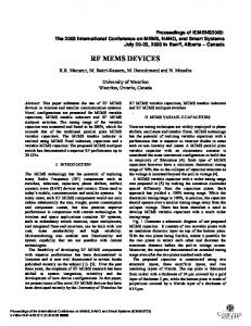
After separating the real and imaginary parts of Equation (3), a system of two nonlinear algebraic equations was obtained: the layer thickness (fixed at 2 µm), and both the ZnO and BN bulk shear wave velocities and density, the liquid density and viscosity were the equations parameters, while the wave velocity and attenuation were the unknowns. The system was solved numerically using the Newton-Raphson method implemented with Matlab, assuming that the free ZnO layer surface is loaded with a viscous Newtonian liquid (water) with mass density ρl = 1000 kg/m3 and viscosity η = 0.001 Pa¨ s. The perturbed operating frequency was estimated by the relation f = vwater /λ where v is the Love wave velocity calculated by the dispersion Equation (3) and λ is the wavelength „ (equal to the pv air ´ vwater q IDTs periodicity). Figure 11 shows the attenuation α and the relative velocity change v air due to the presence of the viscous liquid, for different ZnO thicknesses. Also shown in ˜ normalized ¸ v gr p∆v{vq f Figure 11 is the viscosity sensitivity, evaluated as Sη “ , i.e., the relative frequency v ph pρl δq a change per unit viscous liquid mass ml “ ρl ¨ δ “ 2ηρ{ω, for different layer thicknesses. As it can be seen in Figure 11, there is an optimum ZnO layer thickness corresponding to the enhanced sensor sensitivity. The highest sensitivity value, equal to 280 m2 ¨ kg´1 , and corresponding to an operation frequency of 354 MHz, is quite larger than that (approxmately 45 m2 ¨ kg´1 ) calculated in [26] and referred to a quartz substrate covered by a SiO2 layer, 6.5 µm thick, and operating at 124 MHz.
2
, for different layer thicknesses. As it can be seen in Figure 11, there is an optimum ZnO layer thickness corresponding to the enhanced sensor sensitivity. The highest sensitivity value, equal to 280 m2·kg−1, and corresponding to an operation frequency of 354 MHz, is quite larger than that (approxmately 45 m2·kg−1) calculated in [26] and referred to a quartz substrate covered by a SiO2 Micromachines 2016, 7, 15 11 of 13 layer, 6.5 μm thick, and operating at 124 MHz.
Figure 11. 11. TheThe attenuation andthe therelative relative velocity changes to the presence of the viscous Figure attenuationαα and velocity changes due to due the presence of the viscous liquids. liquids.
5. Conclusions Love sensors are likely to see increased competition from devices such as Lamb wave sensors for gravimetric applications in liquid media; the acoustic plate modes have the disadvantage of requiring bulk micromachining, whereas the formers can be fabricated using well established surface micromachining. Additionally, Love wave devices are more robust, can operate in a harsh environment and have operation capability on a wireless platform, which makes it possible to operate these devices from a remote location. There is a wide range of combinations of materials of which the devices can be made to improve the velocity (choosing fast materials), the electroacoustic coupling efficiency (choosing materials with a high piezoelectric coupling), the thermal stability (by choosing materials with a temperature coefficient delay opposite in sign) and resistance to harsh environments (choosing materials able to survive at high temperatures and in chemically aggressive environments). A proper sensor device design is required to trade off mass sensitivity as well as electromechanical coupling, which affects device size and insertion loss. Since there is no material combination which outperforms all others in these two areas, the research for substrate and layer configurations with favourable properties is still in progress. In the present paper we studied conventional piezoelectric substrates, such as ST-Y quartz, and unconventional piezoelectric substrates, such as c-axis tilted AlN, ZnO, GaN and InN, to be used as Love wave propagating media suitable for the implementation of high-frequency, enhanced-coupling sensor devices. Our theoretical study demonstrates that Love mode devices on c-axis inclined ZnO/BN substrate can offer remarkable performance, with qualities such as high velocity (and hence operating frequency), quite good K2 (4%), and high sensitivity. In terms of feasibility, this acoustic waveguide is reliable and compatible with semiconductor processing techniques, thus offering the advantage of providing the monolithic integration of the device with the signal processing electronics. Acknowledgments: This work has been partially supported by Mouloud Mammeri University of Tizi Ouzou (UMMTO), Algeria. The authors wish to thank the Institute of Photonics and Nanotechnology of Rome, IFN-CNR, that hosted them during the course of this research. Author Contributions: Cinzia Caliendo conceived the research and performed the calculations referred to in Sections 3 and 4.1.; all three authors performed the calculations shown in Sections 2 and 4.2 and wrote the manuscript. Conflicts of Interest: The authors declare no conflict of interest.
Micromachines 2016, 7, 15
12 of 13
References 1. 2. 3. 4. 5.
6. 7. 8. 9. 10. 11. 12. 13. 14. 15. 16.
17. 18. 19. 20. 21. 22. 23.
Caliendo, C.; DAmico, A.; Verardi, P.; Verona, E. K+ detection using shear horizontal acoustic modes. In Proceedings of the IEEE Ultrasonics Symposium, Honolulu, HI, USA, 4–7 December 1990; pp. 383–387. Gizeli, E.; Stevenson, A.C.; Goddard, N.J.; Lowe, C.R. A novel Love-plate acoustic sensor utilizing polymer overlayers. IEEE Trans. Ultrason. Ferroelectr. Freq. Control 1992, 39, 657–659. [CrossRef] [PubMed] Kovacs, G.; Lubking, G.W.; Vellekoop, M.J.; Venema, A. Love waves for (bio)chemical sensing in liquids. In Proceedings of the IEEE Ultrasonics Symposium, Tucson, AZ, USA, 20–23 October 1992; pp. 281–285. Levinshtein, M.E.; Rumyantsev, S.L.; Shur, M.S. Properties of Advanced Semiconductor Materials: GaN, AIN, InN, BN, SiC, SiGe; John Wiley and Sons: New York, NY, USA, 2008. Choy, M.M.; Cook, W.R.; Hearmon, R.E.S.; Jaffe, H.; Jefphagnon, J.; Kurtz, S.K.; Liu, S.T.; Nelson, D.F. Elastic, Piezoelectric, Pyroelectric, Piezooptic, Electrooptic Constants, and non Linera Dielectric Susceptibilities of Crystals: Numerical Data and Functional Relationships. In Landolt-Börnstein, Numerical Data and Functional Relationships in Science and Technology, New Series, Group III: Crystal and Solid State Physics; Hellwege, K.-H., Hellwege, A.M., Eds.; Springer-Verlag: Berlin, Germany, 1979; Volume 11. Newton, M.I.; Roach, P.; McHale, G. ST Quartz Acoustic Wave Sensors with Sectional Guiding Layers. Sensors 2008, 8, 4384–4391. [CrossRef] Du, J.; Harding, G.L.; Ogilvy, J.A.; Dencher, P.R.; Lake, M. A study of Love-wave acoustic sensors. Sens. Actuators A Phys. 1996, 56, 211–219. [CrossRef] Turton, A.C.; Bhattacharyya, D.; Wood, D. High sensitivity love-mode liquid density sensors. Sens. Actuators A Phys. 2005, 123–124, 267–273. [CrossRef] Jakoby, B.; Vellekoop, M.J. Properties of Love waves: Applications in sensors. Smart Mater. Struct. 1997, 6, 668. [CrossRef] Harding, G.L.; Du, J. Design and properties of quartz-based Love wave acoustic sensors incorporating silicon dioxide and PMMA guiding layers. Smart Mater. Struct. 1997, 6, 716. [CrossRef] Kadota, M.; Miura, T. Shear Bulk Wave Transducer Made of (1120)Plane Epitaxial ZnO Film on R-Sapphire. Jpn. J. Appl. Phys. 2002, 41, 3281–3284. [CrossRef] Lee, Y.E.; Kim, S.G.; Kim, Y.J.; Kim, H.J. Effect of oblique sputtering on microstructural modification of ZnO thin films. J. Vac. Sci. Technol. A 1997, 15, 1194. [CrossRef] Wasa, K.; Hayakawa, S.; Hada, T. Excitation of Shear Mode Elastic Waves in Co-Sputtered ZnO Films. IEEE Trans. Sonics Ultrason. 1974, 21, 298–299. [CrossRef] Foster, N.F. Cristallographic Orientation of Zinc Oxide Films Deposited by Triode Sputtering. J. Vacuum Sci. Technol. 1969, 6, 111–114. [CrossRef] Lehmann, H.W.; Widmer, R. RF sputtering of ZnO shear-wave transducers. J. Appl. Phys. 1973, 44, 3868–3879. [CrossRef] Yanagitani, T.; Mishima, N.; Matsukawa, M.; Watanabe, Y. Electromechanical coupling coefficient k15 of (1120) textured ZnO films. In Proceedings of the IEEE Ultrasonics Symposium, Rotterdam, The Netherlands, 18–21 September 2005; pp. 1824–1827. Hu, C.; Kotake, S.; Suzuki, Y.; Senoo, M. Boron nitride thin films synthesized by reactive sputtering. Vacuum 2000, 59, 748–754. [CrossRef] Deng, J.-X.; Zhang, X.-K.; Yao, Q.; Wang, X.-Y.; Chen, G.-H.; He, D.-Y. Optical properties of hexagonal boron nitride thin films deposited by radio frequency bias magnetron sputtering. Chin. Phys. B 2009, 18, 4013–4018. Chen, X.; Sun, L.; Yang, B.; Guo, Y.; Wu, X. Research on the piezoelectric response of cubic and hexagonal boron nitride films. Optoelectron. Lett. 2012, 8, 117–120. [CrossRef] Sun, L.; Chen, X. Research on the h-BN films for high frequency SAW devices. Proc. SPIE 2011, 8202, 82020L. Caliendo, C. Theoretical and experimental investigation of gigahertz-band, temperature-compensated electromechanical coupling configurations based on AlN films. Appl. Phys. Lett. 2008, 92, 033505. [CrossRef] Campbell, C.K. Surface Acoustic Wave Devices for Mobile and Wireless Communications; Academic Press: Cambridge, MA, USA, 1998. Campbell, J.J.; Jones, W.R. A method for estimating optimal crystal cuts and propagation directions for excitation of piezoelectric surface waves. IEEE Trans. Sonics Ultrason. 1968, 15, 209–217. [CrossRef]
Micromachines 2016, 7, 15
24.
25. 26.
13 of 13
Smith, W.R.; Gerard, H.R.; Collins, J.H.; Reeder, T.M.; Shaw, H.J. Analysis of Interdigital Surface Wave Transducers by Use of an Equivalent Circuit Model. IEEE Trans. Microw. Theory Tech. 1969, 17, 856–864. [CrossRef] Kiełczynski, ´ P.; Szalewski, M.; Balcerzak, A. Effect of a viscous liquid loading on Love wave propagation. Int. J. Solids Struct. 2012, 49, 2314–2319. [CrossRef] McMullan, C.; Mehta, H.; Gizeli, E.; Lowe, C.R. Modelling of the mass sensitivity of the Love wave device in the presence of a viscous liquid. J. Phys. D Appl. Phys. 2000, 33, 3053–3059. [CrossRef] © 2016 by the authors; licensee MDPI, Basel, Switzerland. This article is an open access article distributed under the terms and conditions of the Creative Commons by Attribution (CC-BY) license (http://creativecommons.org/licenses/by/4.0/).