IEEE SENSORS JOURNAL, VOL. 10, NO. 2, FEBRUARY 2010
331
Low-Cost Autonomous 3-D Monitoring Systems for Hydraulic Engineering Environments and Applications With Limited Accuracy Requirements Nihal Kularatna, Senior Member, IEEE, James Mc Dowall, Bruce Melville, Dulsha Kularatna-Abeywardana, Aiguo Patrick Hu, Senior Member, IEEE, and Ambuj Dwivedi
Abstract—The details of developing autonomous 3-D motion monitoring systems based on commercial off-the-shelf (COTS) motion sensors for hydraulic environments are discussed. Possible areas of application, are river bed sediment transport monitoring and monitoring the agitation and other physical parameters inside milk vats with a mechanized agitator. Simplified calculations of inertial navigation systems (INSs) such as Euler angle method, MATLAB programs for further processing, power management systems for autonomous operation including the possibility of inductive power transfer (IPT) and use of microelectromechanical systems (MEMS) technology are discussed. Experimental results for proof of concept systems are highlighted. Index Terms—Autonomous 3-D monitoring, Euler angle method, inductive power transfer, inertial navigation systems (INSs), microelectromechanical systems (MEMS).
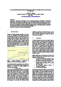
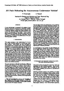
I. INTRODUCTION Fig. 1. Test arrangement using the smart sediment particle.
A
PPLIED research on microelectromechanical systems (MEMS) is widely reported. Low-cost MEMS, developed for automotive and consumer electronics, have been used in advanced engineering applications [1]–[3], including environmental and space technology. These publications show that modern accelerometers and gyro ICs are usable in strap-down inertial platforms for specialized applications, if the cumulative errors are managed with adequate accuracy. One potential application of such MEMS devices is in the development of a smart sediment particle for studies of sediment transport in rivers and elsewhere. The smart sediment particle would provide significant insight into the process of sediment
Manuscript received April 20, 2009; revised September 23, 2009 acceptedSeptember 24, 2009. Current version published December 28, 2009. This work was supported in part by the Department of Civil and Environmental Engineering, University of Auckland, Auckland, New Zealand. This is an expanded paper from the IEEE SENSORS 2008 Conference. The associate editor coordinating the review of this paper and approving it for publication was Prof. Evgeny Katz. N. Kularatna is with the Department of Engineering, University of Waikato, Hamilton 3240, New Zealand (e-mail:
[email protected]). B. Melville and A. Dwivedi are with the Department of Civil and Environmental Engineering, University of Auckland, Auckland 1010, New Zealand (e-mail:
[email protected]). J. Mc Dowall is with the Department of Engineering, School of Science and Engineering, University of Waikato, Hamilton 3240, New Zealand. D. K. Abeywardana and A. P. Hu are with the Department of Electrical and Computer Engineering, University of Auckland, Auckland 1010, New Zealand. Color versions of one or more of the figures in this paper are available online at http://ieeexplore.ieee.org. Digital Object Identifier 10.1109/JSEN.2009.2034294
entrainment [4], which would impact on diverse fields including river flooding. The granular material (sand and gravel) in the riverbeds are typically in motion during periods of high river flow and stationary at other times. One of the most intriguing problems of this sediment transport process is the cause of the initial motion, i.e., the “entrainment” or pickup, of individual sediment grains. Fig. 1 depicts the test arrangement for use of the smart sediment particle in experiments designed to elucidate the sediment entrainment process. As shown, the smart particle will be positioned amongst a bed of similar (fixed) particles. Miniature load cells will be used to measure the interparticle forces between the smart particle and its neighboring fixed particles. The measurements of the motion of the smart particle, the interparticle forces, and the flow turbulence will be used to develop a conceptual model of the entrainment process. The conceptual model will represent a most significant advance in understanding of the process of sediment transportation. During the last four years, the authors were involved in developing different aspects of this smart sediment particle using commercial off-the-shelf (COTS) devices such as accelerometers and gyroscope ICs with suitable electronic subsystems such as processing, energy and power management, external interfacing and communications, and the essential base for the mathematical manipulations.
1530-437X/$26.00 © 2009 IEEE Authorized licensed use limited to: Nihal A.D.V.Kularatna. Downloaded on January 14, 2010 at 01:38 from IEEE Xplore. Restrictions apply.
332
IEEE SENSORS JOURNAL, VOL. 10, NO. 2, FEBRUARY 2010
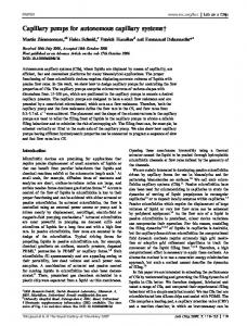
Fig. 3. Axis conversion from body frame to reference frame.
Fig. 2. A milk vat where conditions need to be monitored.
In developing a smart particle for this special application, the following key features were essential in addition to the basic motion-related parameter monitoring capability: i) the physical dimensions of the particle should be only 3 to 4 cm in diameter; ii) underwater operation with its specific gravity close to natural particles; and iii) it should be self contained with an energy source, memory and the ability to determine its location. Another possible application of this concept is in monitoring the conditions inside a milk vat. In a country like New Zealand, milk vats in dairy farms as depicted in Fig. 2 are used to store milk between milking and pick up. The milk vat is used to keep the milk mixed and at a constant temperature of 4 C. If either of these mechanisms fails, the vat of milk will be lost. In developing a milk vat monitoring system, key design goals will be: i) ability to measure temperatures between C to C; ii) monitoring the agitator movement; iii) resistance to weak acids; and iv) suitable communication interface. This paper is organized as follows. Section II describes a generalized set of requirements for hydraulic environments. Section III describes the basis of key mathematical concepts and simplifications for cost-effective implementation. Section IV contains design concepts and variations applicable to two examples, that are discussed, and Section V discusses the future development requirements.
II. GENERALIZED REQUIREMENTS OF A 3-D MOTION PARAMETER MONITORING SYSTEMS FOR LOW ACCURACY REQUIREMENTS In a hydraulic environment application, key design considerations are packaging, powering, relative physical placement of the MEMS, signal conditioning and providing a bare minimum digital subsystem, and a compact and simple data communication interface. The design should accommodate data multiplexing from MEMs, signal conditioning and efficient power management within a very limited volume. In the case of the smart sediment particle, the application requirement specifies that low frequency components of the motion parameters are important within the frequency range up to
20 Hz, with an accuracy in the range of 2%–7%. A key objective is to minimize volume and energy consumption. This suggests the use of a lithium or alkaline cell (or a supercapacitor subsystem with limited battery back up) together with power management circuitry and a miniature digital processing subsystem based on COTS components, while moving almost all complex digital signal processing algorithms to an offline platform. Using video recording and image analysis and sensor calibration techniques, semi-processed motion information can be analyzed with adequate accuracy for the riverbed motion monitoring [5].
III. KEY MATHEMATICAL CONCEPTS AND APPROXIMATIONS Inertial navigation system (INS) concepts [6] are used as the basis of this work. An INS can determine its exact location in 3-D space, relative to a known starting location. The location is resolved by integrating the accelerations and rotations about the three axes. A single triaxial accelerometer and three gyroscopes measure the accelerations and angular rotations about the three axes, giving the particle six degrees of freedom. The reference frame consisting of three axes of the body of the particle is known as the Body Frame. The sensor modules, organized in orthogonal form, measure the accelerations and gyrations with reference to the body frame. As the forces acting on the particle need to be measured relative to a stationary frame of reference, a conversion is necessary. There are several methods of performing a coordinate transformation [6]. The Euler angle method [7] was chosen as the most appropriate method, given the processing and time constraints in the smart sediment particle project. The Euler angle method performs the coordinate transformation as three rotations about the three axes. To transform the body frame related motion parameters to the reference frame, , and are performed around the three angular rotations, , and axes, respectively. When the three rotations are performed as per Fig. 3, we get three matrices representing the rotations as below: Rotation about the reference axis (1)
Rotation
about the new
axis
Authorized licensed use limited to: Nihal A.D.V.Kularatna. Downloaded on January 14, 2010 at 01:38 from IEEE Xplore. Restrictions apply.
(2)
KULARATNA et al.: LOW-COST AUTONOMOUS 3-D MONITORING SYSTEMS FOR HYDRAULIC ENGINEERING ENVIRONMENTS
Rotation
about the new
333
axis
(3)
The three individual matrices can be combined into one complete matrix as follows: (4) is known as the rotation matrix [6]. The complete matrix The conversion of any vector from the body frame to the reference frame is achieved by the multiplication of the body frame vector by the transpose of the rotation matrix. This is indicated in the following:
Fig. 4. Block diagram of the early version of the smart particle.
and will be small enough to use suitable trigonometric approximations. In such a case
(5)
(8)
where This gives the simplified relationship for the reference frame as
vector in the
is the vector in reference frame; is the transpose of the rotation matrix
; (9)
is the vector in the body frame. For the order of rotation in (5), the transpose of the rotation matrix is as shown in the equation at the bottom of the page [6]. The rotation matrix is quite complex and directly implementing it in a DSP subsystem with suitable angular inputs on fast sampling basis is a tedious task and requiring extensive development time. Also, with the proof of a concept project [8] where a simplified mixed signal approach was used it was ascertained that reasonably acceptable accuracies could be achieved based on the following special attributes of the smart particle [9], [10]. In developing a prototype for the smart particle, one important approximation used for simplifying the mathematics involved in the coordinate transformation was the case of and similar trigonometric relationships. In such a situation, vector can be indicated as
(7)
, and are the body frame accelerations where in the corresponding axes. With relatively fast sampling and the angular rotations during the sampling periods being small,
For the angular rotation parameters, the following relationships were used: (10) and are the gyrations in respective axes. where Based on these mathematical relationships, it was decided to have a simple and energy efficient basic motion sensor system. Limited digital blocks were to be used to store A to D converted data, which were to be exported to a suitably developed MATLAB program initially. At the second and third stages of the project [9], [10], a low-power DSP or microcontroller subsystems were used to move more processing into the smart sediment particle. IV. DESIGN CONCEPTS AND IMPLEMENTATION ASPECTS A. Smart Sediment Particle Implementation This work has gone through several stages, commencing with the proof of concept [8] carried out using a mixed mode design. For 3-D motion, up to nine sensor inputs from three orthogonal modules were coupled to a multiplexed analog processing module, and processed by a digital module for data conversion
Authorized licensed use limited to: Nihal A.D.V.Kularatna. Downloaded on January 14, 2010 at 01:38 from IEEE Xplore. Restrictions apply.
334
IEEE SENSORS JOURNAL, VOL. 10, NO. 2, FEBRUARY 2010
Fig. 7. Finally, packaged PIC processor-based system.
Fig. 5. Mathematical flow of obtaining the distance traveled along each axis.
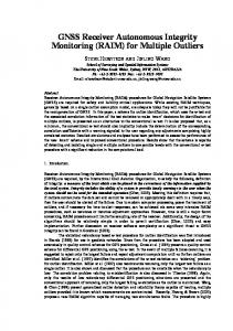
Fig. 8. Block diagram of an experimental milk vat monitoring system.
Fig. 6. Total system block diagram of the PIC processor-based system including off line MATLAB processing.
and storage. Fig. 4 depicts the block diagram of the early version of the design [8]. In a subsequent version of the system with a fully digital implementation, a PIC18F8520 type microprocessor was used, together with an external flash memory of the type SST25VF020 for storing raw sensor data. COTS type accelerometers and gyroscope MEMS from Analog Devices were considered based on their sensitivity, accuracy, noise behavior and the offset as well as the total cost of the system. ADXL202 dual axis accelerometers and ADXRS150 yaw rate gyroscopes were found suitable. These devices were placed in three orthogonal sensor modules with suitable signal conditioning circuitry. Concept of processing used is shown in Fig. 5. Fig. 6 depicts the block diagram of the system based on the PIC processor, and Fig. 7 depicts the packaging of the system. A 6 V battery generally powers the circuit up to about 15 min continuously. A Texas Instruments TPS60132 charge pump was
utilized to regulate the supply voltage of the pebble at 5 V. Additionally, it boosts the battery voltage as it dips below 5 V. The entire system works on 5 V, except for the external flash memory which requires 3 V supplied through a REG102 3 V regulator. Using dual axis accelerometers it was possible to take all the necessary measurements with two chips to keep the real estate of the PCBs to a minimum. Each sensor produces an analogue voltage proportional to the acceleration or gyration measured. These outputs are periodically scanned and averaged out to minimize noise, through the analogue-to-digital-converter channels of the Microchip PIC18F8520 microcontroller. The digitized sensor data are then stored in an external flash memory, SST25VF020. Since the data are collected at regular time intervals, these data are later processed to determine the motion of the smart particle. For details [9] is suggested. Calibration of the device was done using several methods including a slope and a shaft encoder as well as using a shake table [9], [10]. B. Milk Vat Sensor System Compared to the restrictions on the physical size of the smart particle, which is expected to be in water for about 15 min, a milk vat sensor system can be slightly larger in PCB real estate, but it needs to be kept inside the vat for a much longer time, i.e., for several days. Also, it is expected to communicate regularly with the external world. Hence, in this system, we need a communication subsystem as well. Also, battery and power management systems need to be optimized for prolonged operation. For this reason, it is expected to run at slower sampling rates than the smart particle, which runs at sampling rates from about 500 Hz to 1 kHz. Fig. 8 indicates the block diagram of a milk vat monitoring system. Fig. 9(a) indicates the block diagram of the power management system and the sampling rate versus the expected battery life. Fig. 9 indicates some measured results of a proof of concept based on a PIC processor.
Authorized licensed use limited to: Nihal A.D.V.Kularatna. Downloaded on January 14, 2010 at 01:38 from IEEE Xplore. Restrictions apply.
KULARATNA et al.: LOW-COST AUTONOMOUS 3-D MONITORING SYSTEMS FOR HYDRAULIC ENGINEERING ENVIRONMENTS
335
Fig. 9. Power management concept and the battery life of the milk vat monitoring system.
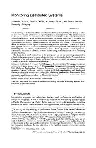
Fig. 10. Information logged by the milk vat sensor over a limited time period. (a) Temperature log. (b) Accelerometer data for agitator activity.
Fig. 11. Gyro error sources for ADXRS150 from analog devices. (a) Stability of the rate output over 1 hour. (b) Effect of random vibration on rate axis at sample rate of 1/60 s. [Source [21].]
V. ERROR SOURCES AND CALIBRATION In the two applications discussed, smart pebble development requires adequate attention to error sources and calibration aspects, while the milk vat monitor does not require serious attention to error sources except for the temperature measurement accuracy. In addition to the common and obvious errors [11] such as the (where is the least significant quantization error, bit value), differential and integral nonlinearities, etc., there are quite a few significant error sources in MEMs given the nature of their design and the size. These situations, as applicable to the smart pebble are briefly discussed here due to intellectual property reasons. Further work is in progress. When using a microcontroller with a 10-bit ADC and a reference voltage of 5 V, is 0.0049 V. This creates an rms quantization error of 0.0014 V. Although this is an insignificant value when considered individually, the cumulative error created over a period of time would lead to a significant error. In the case of smart pebble, we have used accelerometers [15] and gyroscope ICs [20] from Analog Devices, Inc. (ADI). Given the mathematical concepts applicable to the pebble, in the Euler angle method of calculations, some errors significant to accelerometers and gyroscopes could lead to significant inaccuracies. Particular attention is required on the offset errors of accelerometer ICs, and the rate bias (or the null and sensitivity drift) as specified in the data sheets, in addition to the acceleration sensitivity of the gyroscope chips used. ADI data sheets specify this rate bias to be within 300 /hour, based on a three point calibration technique [20]. In these gyro devices where
Fig. 12. Cumulative angle error over a single measurement period.
the rate is given as directly proportional voltage output, the null stability is within the limits shown as per graph of Fig. 11. Apart from these errors, the assumptions that and also can lead to significant errors in the calculations after some time. Therefore, it is evident that the direction cosine matrix, which is relied upon to perform the axis transformation, is not completely accurate and can create a cumulative error after some time. Velocity and position errors in an INS are mainly due to attitude errors as discussed previously [3]. Inaccuracies in measurements of the specific force provided by
Authorized licensed use limited to: Nihal A.D.V.Kularatna. Downloaded on January 14, 2010 at 01:38 from IEEE Xplore. Restrictions apply.
336
IEEE SENSORS JOURNAL, VOL. 10, NO. 2, FEBRUARY 2010
Fig. 13. Effect of random vibrations, etc., on the accelerometers and the use of smart algorithms to compensate. (a) Pickup of random vibrations by the accelerometers with a lab setup. (b) Effect of filtering and averaging algorithms.
the accelerometers also contribute to errors in velocity and position calculation. Errors in the Coriolis terms, differences in the local gravity vector and incorrect assumptions about the shape of the earth although negligible, also make a difference in calculations. For a short duration and for short range motion parameter estimation, the last three error sources are negligible. Though there are more accurate rate sensors in the market [20], [21] including complete inertial measurement units [22] where these errors could be made insignificant in an applications like smart pebble, size and cost limitations prohibit the use of these. Given the total measurement period of around 15–20 min, this if the situation allows using approximations such as sampling rate is around 10 Hz or higher. Fig. 13(a) indicates the effect of random vibration pickups within the measurement environments in laboratories, while Fig. 13(b) indicates the effectiveness of filtering and averaging algorithms used in external programs. Choosing the correct sampling frequency is vital to avoid undesired amplitude errors [5], [7]. The time-domain amplitude error between the sampled signal and the real signal is directly proportional to the ratio between signal amplitude and range of the ADC. The amplitude error can be approximated as
Fig. 14. Effect of sampling frequency on the pebble performance: (a) at 9 Hz sampling rate and (b) increased sampling rate at 70 Hz.
is the peak value of the input signal, BW is the bandwidth is the of the signal, is the sampling frequency and full scale ADC range. Therefore, it is apparent that increasing both the sampling frequency and the ADC range can reduce the amplitude error. Fig. 14 depicts the effect of sampling rate variations using a shake table measurement set up with shake table vibration set to 3.5 Hz. Fig. 14(a) indicates the case of approximately 9 Hz of sampling rate, where high errors between 60%–92% during some sample. Fig. 14(b) indicates the reduction of the same to about 5% when the sampling rate is increased to 70 Hz at the same frequency of shake table excitations. VI. DESIGN IMPROVEMENTS AND ADVANCED POWER MANAGEMENT The design is currently undergoing some major changes including a new power supply and a new microcontroller. A Silicon Labs C8051F921 microprocessor has been introduced, which operates on a DC supply as low as 0.9 V, to lower the power consumption of the circuitry significantly, [13], [14]. The microminiaturized packaging of 4 4 mm, will further reduce the PCB real estate. Currently, developments are underway to replace the previous PIC18F8520 microcontroller.
Authorized licensed use limited to: Nihal A.D.V.Kularatna. Downloaded on January 14, 2010 at 01:38 from IEEE Xplore. Restrictions apply.
KULARATNA et al.: LOW-COST AUTONOMOUS 3-D MONITORING SYSTEMS FOR HYDRAULIC ENGINEERING ENVIRONMENTS
TABLE I COMPARISON BETWEEN MICROCONTROLLERS
Table I compares the two microcontrollers in terms of the most important features. The most critical microcontroller feature required for this design is the Analog-to-Digital Converter (ADC). The C8051F921 has a 10-bit successive-approximation-register (SAR) ADC. [13]. This is an added advantage in power conservation. The 16-bit accumulator is capable of automatically over sampling and averaging the ADC data [12]. The single ADC in the microcontroller is capable of multiplexing up to 23 input channels, with the in-built multiplexer [13] allowing the sensor readings into the microcontroller, on demand. To maintain precision timing between samples a timer within the processor is used. With the microcontroller operating on a voltage as low as 1.8 V, the reference source of the ADC is vital. The reference voltage can be either external or one of two internal reference or . With voltages. The gain settings can be set to either mode a full scale reading is determined by the reference the voltage and the mode allows a full scale reading to go as high as twice the reference voltage [13]. To ensure low-power operation the supply voltage is maintained at the typical value of 1.2 V which keeps the ADC reference voltage also at the same value. Therefore, the maximum ADC reading possible is as low as 2.4 V. With the ADC reference voltage dropping down significantly, precision voltage dividers are being introduced to the sensor outputs to bring them within the range of the microcontroller. However, by introducing a new triaxial accelerometer, which operates within the same supply range as the microcontroller, this feature can be controlled further. The ADXL335 triaxial accelerometer is also currently being introduced to the system, to replace the two dual axis accelerometers. The two key advantages here are the PCB real estate reduction and lower power consumption. This sensor works within a supply range of 1.8–3.6 V, which coincides with the power supply range of the microcontroller [15]. Table II outlines a comparison between the most important characteristics of the two sensors. The previous design of the smart particle used a single 6 V alkaline battery as its power source. The new version uses a completely new power supply design based on super capacitors and Inductive Power Transfer (IPT) technology, which is currently being implemented. IPT allows contactless power transfer, with magnetic fields directly linking energy to where required [16]. IPT technique have been licensed to industrial clean rooms and factory automation systems internationally by
337
TABLE II COMPARISON BETWEEN ACCELEROMETERS
Fig. 15. IPT power supply design.
Auckland UniServices Limited, commercial arm the University of Auckland [16]. An IPT system magnetically couples primary and secondary components. The primary component is a power supply with a power converter and a loop or track coil carrying high-frequency (10–300 kHz) and high magnitude (10–300 A) alternating current. The primary side of the IPT power supply serves as a charging station which can be in the form of a container for this project. The secondary component is a movable pickup with a pickup coil and power conditioning. An inductive electromotive force is induced in the pickup coil and the power conditioner regulates power as required [17]. The pickup will be placed within the smart particle and the key challenge is to design a miniaturized pickup circuit which can efficiently extract power to charge the internal power supply. The power obtained by the pickup circuitry can be used to charge a rechargeable cell. However, the battery will simply be a backup power source while an array of super capacitors will be the primary energy source. The power picked up over the IPT system will charge these super capacitors which are as large as 10 F. Supercapacitors alone cannot be used as an energy source due to their fast energy release, but together with a battery can serve as a “hybrid battery” [20]. Reference [20] details many advantages of supercapacitors including their long life, low ESR, rapid charge capability, etc. This new rechargeable IPT power supply addresses the problem of frequent opening of the device for battery replacement. Therefore, the waterproofing will remain intact and the cost of batteries will be eliminated. It is important to miniaturize this part of the circuitry as much as possible so that the smart particle size will not need to be expanded.
Authorized licensed use limited to: Nihal A.D.V.Kularatna. Downloaded on January 14, 2010 at 01:38 from IEEE Xplore. Restrictions apply.
338
IEEE SENSORS JOURNAL, VOL. 10, NO. 2, FEBRUARY 2010
VII. CONCLUSION
Fig. 16. Three-dimensional IPT setup.
This paper describes the theoretical and practical design aspects of a smart particle usable for monitoring of the 3-D motion parameters of the particle, including the rotations around three axes. The possibility of autonomous operation with a battery based energy source for storing and extracting raw data into an offline processing system is proven. The design allows running of the total system for over 10 min with a single alkaline cell. The system approach and the implementation details clearly indicate that due to very short flight times expected in the civil engineering application, and the simplicity of data required in the milk vat monitor, low-cost MEMS are usable. Further work on wireless/contactless charging systems and data communication is in progress.
ACKNOWLEDGMENT The authors appreciate the help of the technical staff members, G. Kirby and G. Carr of the Civil Engineering Laboratories, calibrating the Appreciation also goes to Analog Devices Inc., USA, who supplied us the samples of MEMS required.
REFERENCES
Fig. 17. IPT charging setup for smart particle.
Fig. 15 outlines the basic pickup and primary track outline for the smart particle. Since the smart particle is opaque and is also spherical, precise alignment between the pickup and the track cannot be guaranteed. Generating a 3-D flux field is an option to ensure sufficient power transfer all the time. Multiple primary tracks, fixed in three orthogonal directions will need to be driven accordingly to produce this alternating flux. Fig. 16 illustrates the typical orientation and setup of primary coils to form a 3-D power supply. The three switches S1, S2, and S3 are alternately turned on for one third of the total period. Therefore, a magnetic field is alternately generated in each of the coils for one third of the period [18]. The primary track for the charging unit will be housed within a “charging container” with 3-D power zone. Fig. 17 illustrates the IPT charging setup of the smart particle. In addition to these design improvements, another vital requirement is a wireless data transfer system. Although currently this is not yet fully implemented in the system, it will be added in the future. A possible option is to transfer the data to a surface level buoy and then use standard wireless communication technologies to relay the data from that point onwards. Upon completion of the new communication system design, the power requirement is expected to reduce significantly. Also the adoption of the new microcontroller will greatly contribute towards minimizing the PCB real estate of the smart particle. A detailed discussion on error estimation and improvements will be another major task for the ongoing work.
[1] N. Barbour and G. Schmidt, “Inertial sensor technology trends,” IEEE Sensors J., vol. 1, no. 4, pp. 332–339, Dec. 2001. [2] T. G. Brown et al., “Strap-down micromechanical (MEMS) sensors for high-G munition applications,” IEEE Trans. Magn., vol. 37, no. 1, Jan. 2001. [3] J. Tieman et al., “Design of a MEMS based 3-axis accelerometer smart sensor,” in Proc IEEE Sensors Industry Conf., Nov. 2002, pp. 19–23. [4] S. E. Coleman and B. W. Melville, “Initiation of bed forms on a flat sand bed,” J. Hydraulic Eng., ASCE, vol. 122, no. 6, pp. 301–310, Jun. 1996. [5] M. H. Garcia, F. Lopez, and Y. Nino, “Characterization of near-bed coherent structures in open channel flow using synchronized high-speed video and hot film measurements,” Experiments in Fluids, vol. 19, pp. 16–28, 1995. [6] D. H. Titerron and J. L. Weston, Strapdown Inertial Navigation Technology, 2nd ed. London, U.K.: IEE, 2004. [7] R. Pio, “Euler angle transformations,” IEEE Trans. Autom. Control, vol. 11, no. 4, pp. 707–715, Oct. 1966. [8] N. Kularatna, B. W. Melville, and C. Wijeratne, “Mixed signal approach for rapid prototyping of a compact smart pebble for sediment transport monitoring in river beds,” in Proc. IEEE Sensors, Oct. 2005, pp. 1128–1132. [9] N. Kularatna, B. W. Melville, E. Akeila, and D. Kularatna, “Implementation aspects and offline digital signal processing of a smart pebble for riverbed sediment transport monitoring,” in Proc. IEEE Sensors, Daegu, Korea, Oct. 22–25, 2006, (Paper ID 1332). [10] N. Kularatna and D. K. Abeywardana, “Use of use of motion sensors for autonomous monitoring of hydraulic environments,” in Proc. IEEE Sensors, Lecce, Italy, Oct. 26–29, 2008, (Paper ID 6810). [11] P. H. Garret, High Performance Instrumentation and Automation. Boca Raton, FL: CRC Press and Taylor & Francis Group, 2005. [12] E. Akeila, Z. Salcic, N. Kularatna, B. W. Melville, and A. Dwivedi, “Testing and calibration of smart pebble for river bed sediment transport monitoring,” in Proc. IEEE Sensors Conf., Atlanta, GA, 2007, pp. 1201–1204. [13] Silicon Laboratories Inc.,, C8051F93x-C8051F92x Data Sheet, Revision 0.4. [14] Microchip Technology Inc.,, PIC18F6520/8520/6620/8620/6720/8720 Data Sheet, Revision B, 2004. [15] Analog Devices Inc.,, ADXL335 Data Sheet, Revision 0, 2009. [16] Inductive Power Transfer. Auckland, New Zealand: Auckland UniServices Limited, Nov. 8, 2008, viewed.
Authorized licensed use limited to: Nihal A.D.V.Kularatna. Downloaded on January 14, 2010 at 01:38 from IEEE Xplore. Restrictions apply.
KULARATNA et al.: LOW-COST AUTONOMOUS 3-D MONITORING SYSTEMS FOR HYDRAULIC ENGINEERING ENVIRONMENTS
[17] , [Online]. Available: http://www.uniservices.co.nz/pageloader. aspx?page=755d8d0d82 [18] A. P. Hu, J. T. Boy, and G. A. Covic, “Frequency analysis and computation of a current-fed resonant converter for ICPT power supplies,” in Proc. Int. Conf. Power Syst. Technol. (PowerCon 2000), Dec. 4–7, 2000, vol. 1, pp. 327–332. [19] P. Si, “Wireless power supply for implanatable biomedical devices,” Ph.D. dissertation, University of Auckland, Auckland, New Zealand, 2008, unpublished. [20] Super Capacitors, , Feb. 27, 2009 [Online]. Available: http://www.supercapacitors.org/, viewed [21] Analog Devices, ADXRS150, Data Sheet Revision B, 2004. [22] A. M. Madni, L. E. Costlow, and S. J. Knowles, “Common design techniques for BEI GyroChip quartz rate sensors for both automotive and aerospace/defense markets,” IEEE Sensors J., vol. 3, no. 5, pp. 569–578, Oct. 2003. [23] R. Hulsing, “MEMS inertial and acceleration sensor,” in Proc. IEEE Position Location and Navigation Symp., Apr. 20–23, 1998, pp. 169–176. [24] P. W. Seong-Hoon, G. Farid, and W. M. Wael, “A fastening tool tracking system using an IMU and a position sensor with Kalman filters and a fuzzy expert system,” IEEE Trans. Ind. Electron., vol. 55, no. 5, May 2009.
Nihal Kularatna (SM’98) received the B.Sc.Eng. (Hons.) degree from the University of Peradeuiya, Peradeuiya, Sri Lanka, in 1976. After ten years of employment in the aviation and telecommunications industries, he joined the Arthur C. Clarke Institute for Modern Technologies, Sri Lanka, as an R&D Engineer in 1985. He was a Principal Research Engineer in 1990 and was appointed the CEO of the Institution in 2000. He was a consultant for several U.S. companies and Sri Lankan organizations including the Gartners Group, USA. He has also served as a Board Member/Assistant Commissioner for the Sri Lanka Inventors Commission and also was a select Committee Member for the Presidential Fund for Inventors and Innovators in Sri Lanka. From 2002 to 2005, he was a Senior Lecturer at the Department of Electrical and Computer Engineering, University of Auckland, Auckland, New Zealand, and is currently with the University of Waikato, Hamilton, New Zealand. He is on the Expert Reviewer Panel of the Foundation for Research, Science and Technology (FRST), New Zealand. He has authored or coauthored seven books including Volumes 10 and 11 of Electrical Measurement Series books for the IEE (London) and Electronic Circuit Design-From Concept to Implementation (CRC Press, Boca Raton, FL, 2008). He has contributed over 65 papers to academic and industry journals and international conference proceedings. He is currently active in research in transient propagation and power conditioning area in power electronics, and smart sensor systems. Mr. Kularatna is a Fellow of the IET (London), a Fellow of the Institution of Engineers (Sri Lanka), and a Member of The Institution of Professional Engineers, New Zealand. During his research career in Sri Lanka, he was a winner of Presidential Awards for Inventions (1995), the Most Outstanding Citizens Awards (1999) (Lions Club), and a TOYP Award for Academic Accomplishment (Jaycees) in 1993.
James Mc Dowall graduated from the University of Waikato, Hamilton, New Zealand, in 2007, and is currently employed by ABB, New Zealand.
339
Bruce Melville is a Professor and Head of the Department of Civil and Environmental Engineering, University of Auckland, Auckland, New Zealand. His academic career spans 27 years, prior to which he spent six years working for civil engineering consultants in New Zealand and overseas on water-related projects. He is an active researcher with an international reputation in the field of fluvial sediment transport. His expertise encompasses most aspects of water resources engineering, including hydraulic, hydrological, river, environmental and hydroelectric engineering. He is an Associate Editor of the ASCE Journal of Hydraulic Engineering. He has served on local and international research committees, and has been a member of many tribunals for water consent hearings. He has supervised 20 Ph.D. students and published over 60 refereed journal papers. Prof. Melville received the 2002 ASCE Hydraulic Structures Medal, and was elected to Fellowship of the Royal Society of New Zealand in 2006. In 2007, he received the R. J. Scott Medal from RSNZ for his research contributions.
Dulsha Kularatna-Abeywardana (S’06) graduated from the University of Auckland (UOA), Auckland, New Zealand, with first class honors in 2005 and currently received the M.S. degree in developing certain aspects of the “smart Sediment Particle” at the UOA. She has published several conference papers in international conferences. Her research interests are in smart sensor systems and image processing.
Aiguo Patrick Hu (M’98–SM’07) received the B.E. and M.E. degrees from Xian JiaoTong University, Xian, China, in 1985 and 1988, respectively, and the Ph.D. degree from the University of Auckland, Auckland, New Zealand, in 2001 Before that he worked as a lecturer, director of a technical section, and general manager of a technical development company in China. He holds a few patents in microcomputer control and inductive power transfer technologies. He authored a book on contactless/inductive power transfer, and coauthored a book on electrical machines. He is currently with the Department of Electrical and Electronic Engineering, University of Auckland. His research interests include contactless/wireless power transfer, power converters, and application of power electronics in power systems. Dr. Hu is Chair of the New Zealand North IEEE Power Engineering and Power Electronics Joint Chapter.
Ambuj Dwivedi received the B.E. degree in civil engineering from the National Institute of Technology, Allahabad, India, in 1995 and Master of Technology degree from the Indian Institute of Technology, Roorkee, in 2005. He is currently working towards the Ph.D. degree from the University of Auckland, Auckland, New Zealand. His research interest includes sediment transport and design of “smart sediment” for entrainment studies.
Authorized licensed use limited to: Nihal A.D.V.Kularatna. Downloaded on January 14, 2010 at 01:38 from IEEE Xplore. Restrictions apply.