LOW-NOISE, SENSORLESS COMMUTATION OF BRUSHLESS DC MOTORS Jens Krotsch, András Lelkes, Thomas Zoller ebm Werke GmbH & Co. KG P.O. Box 1161, D-74671 Mulfingen http: //www.ebm-werke.de GERMANY e-mail:
[email protected]
Abstract - Novel, highly optimized commutation electronics for BLDC motors make it possible to reduce costs, increase reliability and reduce motor noise simultaneously. This has been achieved by an advantageous commutation sequence combined with robust sensorless rotor position estimation. The proposed new method is based on a low noise 12-step commutation sequence. An appropriate circuit containing a low cost microcontroller with sophisticated firmware has made it possible to use the motor windings as position sensors by measuring the back electromotive force directly. Thus, costs have been reduced and acoustic motor noise has been lowered drastically. In certain cases up to 20 dB at critical frequencies. I. INTRODUCTION Electronically commutated (EC) motors, also called brushless DC (BLDC) motors, are used in a wide range of applications. This type of motor has some major technical advantages: wide speed range, easy speed controllability and high efficiency. One important market for BLDC motors is fan applications, where low acoustic noise is of increasing importance. Future commutation electronics need to be inexpensive, reliable, user friendly and have to guarantee a low-noise motor operation.
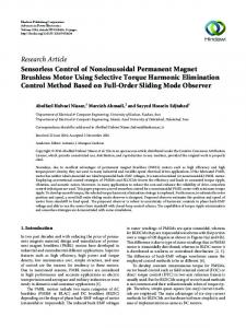
Fig.1: Centrifugal fan unit with external rotor motor in noise measurement room sequence. The next step in the commutation sequence is then carried out, and the current commutates from one motor core to the next. There are six different stator coil excitation steps per electrical revolution. This method is therefore called 6-step commutation. The acoustic noise can be influenced considerably by the commutation strategy. The proposed sensorless 12-step commutation allows costs and acoustic motor noise to be significantly reduced and reliability increased. Furthermore, it can be used with a wide range of motors without any need of parameter adaptation.
For fan applications, external rotor motors are especially advantageous [1]. Figure 1 shows a radial fan unit with such an external rotor brushless motor. On a three-core BLDC motor (Figure 2), most commonly, only two cores are fed with current at the same time. The rotor position is detected by three digital Hall-effect sensors. At each rotor rotation angle of 60° electrical, the output level of one sensor changes in
PCIM 2001 Nürnberg
1/6
T1 V DC
T3
T5 u
+
T2
T4
T6 v
w
Fig.2: Schematic diagram of a three-core brushless motor
Intelligent Motion
a.)
1
2
3
4
5
6
U
V
W
b.) 1
2
3
4
5
6
7
8
9
10
11
12
U
V
W
Fig.3: 6-step (a) and 12-step commutation sequence (b) II. 12-STEP COMMUTATION The usual method for BLDC motor commutation is the 6-step commutation sequence shown in Figure 3a. Except during the commutation process, only two of the three phase windings are excited at any time. The steps change after each 60° electrical. Another, more advantageous method is the 12-step commutation shown in Figure 3b. In this case, additional states are inserted in which all the phase windings are excited. The individual steps alternate after each 30° of electrical rotation angle. In addition, Figure 4 provides a comparison of the current trajectory of the two methods. Figure 5 shows the simulated waveform of the
phase current, and that of the torque. The torque ripple is considerably reduced by 12-step commutation. In addition to the drops in the torque profile, the rapid current changes can also lead to acoustic noise (referred to as commutation noise). This is also considerably reduced with 12-step commutation. Another aspect of 12-step commutation is that, despite these improvements, only one of the six switches has to be modulated for the speed control at any time. The PWM duty cycle can be constant throughout the commutation step. There is no need for any sophisticated threephase modulator and the switching losses remain low in comparison to sinusoidal commutation.
a.)
b.) 5
8
4
9
7
10
6
3
6
11
5 4
12 1
3
1
2
2
Fig. 4: Current trajectory at 6-step (a) and 12-step commutation method (b)
PCIM 2001 Nürnberg
2/6
Intelligent Motion
a.)
b.)
m
m
iU
iU
0
0
t
t
Fig. 5: Torque and current waveforms for the 6-step (a) and 12-step commutation method (b)
III. POSITION ESTIMATOR
In fact, the aim is to find a robust solution that is cost-effective at the same time.
A large number of suitable principles are known for the sensorless determination of rotor position [2]. However, these are often based on sophisticated mathematical methods and models of high complexity, in order to satisfy the stringent requirements for typical drive applications [3]. Generally, however, neither high torque at low speed nor high dynamics are required for fans.
One advantageous approach is position estimation by measuring the synchronous electromotive force. This admittedly has disadvantages at low speeds, but fans are normally operated only in the medium and upper speed ranges, since their output power falls with the cube of the speed.
vU 30°el vN
0
iU
vU = vN 0
t U
V
t1
t2
t3
W
Fig. 6: Method of sensorless rotor-position detection: phase U terminal voltage (vU), neutral-point voltage (vN), motor current (iU)
PCIM 2001 Nürnberg
3/6
Intelligent Motion
The electromotive force can be detected, if one phase is unexcited, but this is never the case with sinusoidal commutation. Fortunately, however, such states exist with the proposed 12step commutation, although they are considerably shorter than with 6-step commutation.
ceases to carry current before the zero crossing, particularly in the upper speed range and during acceleration. This can be achieved by an adequate modulation strategy and by suitable adaptation of the commutation angles.
Figure 6 shows the principle of the position estimation process. The upper switch in phase U is switched off at the time t1. The motor current can flow via the opposite inverse diode of the lower switch. The current falls, until, at the time t2, phase current is zero. Immediately after this, the electromotive force of the unexcited stator phase U can be detected. At the time t3, the terminal voltage vU is equal to the neutral point voltage vN (zero crossing). This event is used by the electronics to detect the rotor position and to switch on the bottom drive in this phase.
IV. SENSORLESS BLDC MOTOR
In case of fans and pumps the torque increases with the square of the speed. Therefore, also the phase current rises. This results in an increase of the time period for the phase winding to get free of current (interval t1 - t2). At the same time the commutation steps (interval t1 - t3) become shorter due to the increasing speed. When t2 ≥ t3, it is no longer possible to identify the rotor position. Preventive measures are therefore worthwhile which ensure that the winding connection
8 bit microcontroller
G1
neutral point voltage simulation
G5
G3 G2
T1
The voltages which can be measured at the motor terminal are passed through low-pass filters (LPF) in order to suppress the PWM frequency in the wanted signal and noise coupled in through the motor supply line. Compensation for the phase frequency response has been found to be advantageous. The voltages produced in this way are compared with a synthetically generated neutral-point voltage. The output signals from the comparators (PU, PV, PW) thus essentially correspond to the polarities of the phase winding voltages. These signals can be processed using a low-cost 8-bit microcontroller, which uses them to estimate the rotor position and actuates the line link as appropriate. Another major task of the microcontroller is fault detection and handling.
PU PV PW
set point feedback
Figure 7 shows a schematic illustration of the proposed system for sensorless commutation of BLDC motors.
G4
T3
G6
T5 LPF
+
U
VDC
LPF
u V W
T2
LPF
T4
v w
T6
Fig. 7: Schematic diagram of the proposed system for sensorless control
PCIM 2001 Nürnberg
4/6
Intelligent Motion
V. OVERHEATING PROTECTION ϑ
In conventional BLDC motors, a further sensor for monitoring the winding temperature is generally provided in addition to the rotor position sensors. The sensor signals are supplied to the external commutation electronics via a separate sensor line, which in many cases is screened, and via plug connections. Although sensorless rotor position estimation alone results in a certain reduction in costs due to the lack of position sensors, the most advantageous solution in terms of costs and availability is, however, to dispense entirely with the additional line and plug connections. These specifically represent a considerably greater cost factor than the sensors themselves. The proposed principle makes this possible by using the winding connecting lines for temperature monitoring as well as rotor position estimation. A low-cost, single-pole overheating switch, which is used in large quantities in single-phase induction motors, is connected in series with at least one winding section of the motor for this purpose, e.g. with one of the motor lines. However, in case of a delta-connected motor, it can be more advantageous to place the switch in series with one phase winding (Figure 8) because of the lower current stress. If overheating occurs, the switch disconnects one winding section and produces an imbalance. This state is reflected in the profile of the comparator signals
changes due to commutation
a.)
changes due to zero-crossing
iU
u
v
w
Fig.8: Proposed overtemperature detection in a delta connected motor
(PU, PV, PW) and is identified by the electronics using the following method. As shown in Figure 9, the successive times tFi between the point of time at which the winding connection ceases to carry current and the point of the zero crossing of the terminal voltage (which can be detected using the same connection) are basically detected and evaluated in this case. In balanced condition (normal operation) and at constant speed, there is no difference between the times tFi and tFi+1 (Figure 9a). The imbalance resulting when the switch contact is open (overtemperature, Figure 9b) results in distinctly different times tFk, tFk+1. This allows the control electronics to detect any faulty situation.
b.)
tFi
tFk
PU
PU
PV
PV
tFi+1
PW
tFk+1
PW iU 0
over temperature shut down
0
iU t
t
Fig.9: Overtemperature monitoring by detecting the terminal voltage zero-crossing (a. normal operation b. overtemperature)
PCIM 2001 Nürnberg
5/6
Intelligent Motion
L [dB]
a
b
f [Hz] Fig.10: Comparison of sound pressure level between a 6-step (a) and 12-step commutation method (b). Fan unit: centrifugal fan (∅ 400 mm) with a brushless external rotor motor at 500 rpm (40 % of rated speed)
VI. EXPERIMENTAL RESULTS
VII. REFERENCES
The proposed sensorless 12-step commutation method has been investigated using an M3G084-FA brushless external rotor motor mounted in an R3G400-AA21-36 centrifugal fan [4]. The commutation electronics made use of a PIC16C72 low cost 8-bit microcontroller. Tests have shown that the proposed method is an advantageous compromise in terms of costs and feasible noise reduction.
[1] Lelkes, A.; Krotsch, J.: Energy saving mains-fed PM synchronous motor with integrated solid state starter. PCIM 2000, Nürnberg. [2] Vas. P.: Sensorless vector and direct torque control. Oxford University Press 1998. [3] Stäbler, M.; Jönsson, R.: Sensorless control algorithms for AC-motors Overview and DSP implementation. PCIM 2000, Nürnberg.
The noise reduction achieved is shown in Figure 10. The sound pressure level was measured in the noise measurement room at ebm. The 12-step commutation method was compared with the common 6-step commutation scheme. The acoustic noise of the motor was reduced significantly, by 20 dB at critical frequencies [5].
[4] EC-Standard (Catalogue for EC motors and fans) ebm Werke GmbH & Co. KG, Mulfingen 2001.
The combination of 12-step commutation with robust, sensorless position estimation and with the proposed temperature monitoring without additional sensor wires makes low-noise operation possible with reduced system costs and increased reliability.
[5] Haas, G.; Krotsch J.: Sensorlose und geräuscharme Kommutierung von bürstenlosen Gleichstrommotoren. IEEE Joint IAS/PELS German Chapter Meeting, Mulfingen 2000. http://www.ewh.ieee.org/r8/germany/ias-pels/
PCIM 2001 Nürnberg
6/6
Intelligent Motion