Lowering Error Floors by Concatenation of Low-Density Parity-Check (LDPC) and Array Code Cinna Soltanpur, Mohammad Ghamari, Behzad Momahed Heravi, Fatima Zare Abstract—Low-density parity-check (LDPC) codes have been shown to deliver capacity approaching performance, however, problematic graphical structures (e.g. trapping sets) in the Tanner graph of some LDPC codes can cause high error floors in bit-errorratio (BER) performance under conventional sum-product algorithm (SPA). This paper presents a serial concatenation scheme to avoid the trapping sets and lower the error floors of LDPC code. The outer code in the proposed concatenation is the LDPC and the inner code is a high rate array code. This approach applies an interactive hybrid process between the BCJR decoding for the array code and the SPA for the LDPC code together with bit-pinning and bit-flipping techniques. Margulis code of size (2640, 1320) has been used for the simulation and it has been shown that the proposed concatenation and decoding scheme can considerably improve the error floor performance with minimal rate loss. Keywords—Concatenated Coding, Low–Density Parity–Check Codes, Array Code, Error Floors.
I. INTRODUCTION
S
INCE their rediscovery by MacKay [1] in 1996 as a class of capacity approaching codes, LDPC codes have found various applications in [2-5]. Using iterative belief propagation techniques such as SPA, LDPC codes can be practically decoded in time-feasible manner linear to their block length [6]. Though, decoding of some LDPC codes using conventional SPA suffer from a weakness in higher signal-to-noise ratios (SNR's) known as error floor [7], [8] which is exhibited as a sudden saturation in BER [7]. The error floor could be troublesome in some communication and data storage systems where BER as low as 10−12 to 10−15 is required. It has been found that trapping sets (or near-codewords) are the main cause of error floors in SPA decoding of LDPC codes over AWGN channel [7], [8]. Recently, many research efforts have been made to mitigate the error floor problem. Some code construction methods have been proposed to avoid trapping sets, thereby lowering the error floors [9], [10]. Trapping sets have sophisticated combinatorial properties and in general it is difficult to find deterministic solutions for lowering error floors through code construction. Other methods aim to lower the error floor by changing structure of decoder [11]. Decoderbased strategies need a prior knowledge of the dominant trapping sets in a particular code through computer simulations or parity-check matrix properties, which is often difficult to obtain. Also, it should be noted for codes with small minimum distances, undetected errors could contribute to high error floors as well [15]. Mohammad Ghamari from University of Texas at El Paso, United States (email:
[email protected])
Decoder-based methods such as bit pinning [13], and bit flipping [15] have been proposed which modify the Log Likelihood Ratio (LLR) values of certain node or check bits to avoid trapping sets. The bit positions might be known from code properties or can be guessed through trial and error [15]. In this work, we propose a concatenation of LDPC and array codes. In the decoding process, LLR values are interchanged between the LDPC decoder (SPA) and the array code decoder (BCJR). Within the LLR interchange, bit-pinning and bitflipping techniques are used be improve the performance. A Margulis LDPC code of length 2640 and rate 0.5 has been used to prove the concept through simulation and it has been shown that the proposed concatenation scheme together with the interactive decoding and bit-pinning/bit-flipping techniques lowers the error floor significantly. II. TRAPPING SETS AND ERROR FLOOR LOWERING TECHNIQUES A (ω, ν) trapping set is a set of ω variable nodes which induce a subgraph with ν odd-degree check nodes which may lead the decoder to error-trap situations from which the decoder cannot escape [7]. Each trapping set is associated with a critical number 𝜖 (where 𝜖 ≤ 𝜈) which is the minimum number of erroneous variable nodes in a trapping set that leads to decoder failure [12]. In any iteration of SPA, if at least 𝜖 number of errors appear in a trapping set, the even-degree check nodes will become mis-satisfied and the odd-degree check nodes which may be referred to as un-satisfied check nodes will trap the errors within the set the decoder fails to converge no matter how many iterations are performed. When an iterative decoder gets "trapped" by the subgraphs associated with trapping sets if there exist a way to inform the decoder with great certainty the value of one or more of the bits in a trapping set, then the iterative decoder would stand a better chance at resolving the values of the other bits in the trapping set [13]. This procedure is somehow possible through bitpinning idea; upon encoding, fix (or pin down) the value of bits for each trapping set of known. The decoder then sets the LLRs for these pinned bits to the maximum possible value. The expense for pinning down these bits is usually very small in code rate and length. Bit pinning is quite similar to code shortening which is to remove selected columns of the code’s parity-check matrix. Removing columns of H in the decoder design is equivalent to setting the corresponding LLR's to infinity, instead of a finite maximum value. In LDPC decoding,
since the trapping sets depends on the decoder input space and the decoding algorithm, it is very difficult to predict trapping sets [14]. In the bit-flipping approach [15], an intuitive idea is to locate all the unsatisfied check nodes to see if there are only a relatively small number of them. In the decoding of each block, the smallest number nc of unsatisfied check nodes throughout the iterations are kept. Also, the set C of these nc unsatisfied check nodes are recorded. If decoding fails and nc is less than a predetermined threshold, then we consider that the decoding failure is caused by a trapping set S, in which C is the set of odd degree check nodes. The wrong bits in hard decision correspond to the set of variable nodes in S, which is denoted by V. To correct the decoding error caused by S, the decoder enters into the second stage. In the second stage, if one can locate all the variable nodes in V, which is difficult, the decoding is completed. In an attempt, a matching set is defined as follows: for a set of check nodes C in a Tanner graph, a matching set of C is a set of variable nodes such that each of them is adjacent to one and only one check node in C. Then, the set L of all the different matching sets of C is generated. At least one of the matching sets in L is a subset of V. The goal is to identify such a matching set from L and use it to correct all the wrong bits. To this end, these bits from subset of L are flipped by setting their initial LLR’s to the maximum possible value with opposite signs, and perform the iterative decoding over again. III. CONCATENATION OF LDPC AND ARRAY CODE The basic idea here is to put LDPC code serially concatenated with an array code. In this configuration the LDPC code is chosen as outer code and array code is the inner code. While the encoding section is kept intact in the proposed method, the decoding stage is modified to fit the SPA decoder. Firstly, information data are encoded with the LDPC code then encoded data are forwarded through an interleaver which would put them in the array form. Single parity check (SPC) codes are calculated easily on each row and column and added to the transmission data. The array code chosen is of very high rate and therefore rate loss due to concatenation is very small. A. LDPC Decoding: SPA In LDPC decoding, the SPA can be seen as belief propagation algorithm. SPA is a soft-decision symbol-bysymbol algorithm which iteratively processes the received symbols to improve their LLR reliabilities [16]. The SPA is further explained in this section in two steps; bit-to-check message passing and check-to-bit message passing which are complemented by initialisation and stopping steps. First, the bit-nodes are initialised by setting the a posteriori probability or the LLR. In AWGN channel, Lj is found by: Lj = LLR(xj |yj) = 2yj /σ2
(1)
the bit-to-check message passing stage, the check nodes values Lij are updated. Lij is the message held in the ith check node (CN) which is to be send to the jth variable node (VN) and is found by Lij = 2tanh−1 ( ∏ tanh(0.5 Lj′ i ))
where Ni/j = Ni − {j} is the set of all VN’s connected to the ith CN (denoted by Ni ) except the jth VN. Lj′i is the VN value which is used to update the ith CN. In the first iteration, Lj′ i is set with the Lj calculated in the initialisation stage. In the checkto-bit stage, the bit nodes values Lji are updated by: Lji = Li + ∑ Li′j
(3)
i′ ∈Mj/i
where Mj/i = Mj − {i} is the set of all CN’s connected to the jth VN (denoted by Mj ) except the ith CN. Then LLR values for each VN is calculated by LLR j = Lj + ∑ Lij
(4)
i∈Mj
B. Array Code Decoding The array code decoding stage is done by either iterative row or column BCJR decoder [17]. The algorithm is briefly explained below. Initialization: Calculate the channel likelihood ratios the same as in the SPA decoder, 𝐿𝑐 𝑦𝑖 , for all received symbols, where channel reliability factor is 𝐿𝑐 = 2⁄𝜎 2.
Decode each row and column: Calculate the extrinsic information, 𝐿𝑖 , for all bits and in every SPC component in each row or column. It should be noted that only the extrinsic information is passed between the decoders in each dimension. Iterations: decoding iteration is complete once all row and column have been decoded. Repeat this decoding process for a fixed number of times. In order to calculate the extrinsic information for each bit in each SPC code, we use similar terms as in SPA for LLR’s 𝑛
𝐿𝑖 (𝑥𝑗 ) = 2𝑡𝑎𝑛ℎ−1 ( ∏ tanh ( 𝑗 ′ =1,≠𝑗
𝐿𝑗′ +𝐿𝑐 ∙𝑦𝑗′ 2
))
(5)
where 𝐿𝑗 ′ is the a priori information of 𝑗 ′𝑡ℎ bit in the i-th iteration. The a priori information is initially zero; however, in subsequent decoding it is the sum of the extrinsic information obtained from decoding rows and columns 𝐿(𝑥𝑗 ) = 𝐿𝑗𝑟𝑜𝑤 + 𝐿𝑗𝑐𝑜𝑙
where Y = {y1 , y2 , … , yj , … , yN }is the received channel values and X = {x1 , x2 , … , xj , … , xN } is the transmitted codeword. In
(2)
j′ ∈Ni/j
(6)
Although both SPA and BCJR use the same LLR concept, it should be noted that the two algorithms are different in basis. In the array code decoder, updates are estimated based on Trellis diagram of dual code which makes the corresponding message passing graph different from the Tanner graph for SPA decoding. C. Hybrid Interactive Decoding (HID) The SPA or any other message passing iterative decoder asserts a failure if it does not converge after a maximum number of iterations. However, if a failure is caused by a trapping set, then there are only a relatively small number of wrong bits and unsatisfied check nodes. A trapping set can be viewed as a state of unstable equilibrium, thus small perturbation might be a way to cope with the failure [15]. The alternated decoding process is as follows. Firstly, the inner BCJR decodes the received codeword and gives out LLR values. After de-interleaving, the LDPC SPA decoder tries to find estimate of original signal. In case that the SPA decoder is unable to converge to a valid codeword and reaches its maximum iteration, the LLR values calculated by the SPA are fed back to the array decoder for a new stage of decoding. The array decoder uses these information and LLR values to try to decode the whole codeword. After a number of iterations, if the decoding was unsuccessful, again inner decoder forwards the LLR values to SPA decoder but this time with the LLR values produced by array code decoding. The interactive process is shown in Fig. 1. We further use combination of concatenation and bit pinning/flipping methods as a hybrid method in which not only the LLR are exchanged between the outer code and inner code but also some changes are made to value of these LLR's. In the interactive scheme, two effective approaches can help to possibly escape from trapping sets; bit-pinning and bit-flipping. In the SPA, the messages from the satisfied check nodes tend to reinforce the current decoder decisions, while the messages from the unsatisfied check nodes try to change some of them. In fact, if we can locate some of the wrong bit nodes, flip or fix them to a number and re-decode the block, it is very likely that the decoder will not get trapped again thus converges to a correct codeword. The idea used in the proposed method is to try to find these bits by array-code decoding. The array code decoder reveals the weak links. Those bit values with small LLR values will be marked as being incorrect and vice versa. In an attempt, we tried to decode the codeword with fixed values. In the flipping case, where bits with low LLR's are targeted, we change the sign and assign a maximum possible value to the LLR. In the bit-pinning case, we assign a maximum possible value to the LLR to the confident bits with large LLRs. The rest of decoding algorithm explained in decoding algorithm below.
Fig. 1. Block Diagram of the Proposed Concatenation
The HID Algorithm: Step 1. Initialize the inner decoder, compute the LLR's for a fixed number of iterations and forward the LLR values to the outer decoder through the interleaver. • Step 2. Compute the first estimate of the outer decoding 𝑜𝑢𝑡 stage through SPA for 𝐼𝑚𝑎𝑥 iterations. Check whether the output of the outer decoder is a valid codeword in C. If it is, label of the received signal L(rx) is the most likely codeword and decoding stops. • Step 3. Interleave information and LLR values from outer decoder to fit into the array format and add array code single parity-check bits. • Step 4. Perform the second stage, inner decoding by the array code algorithm and obtain the estimate of LLR after •
𝑖𝑛 𝐼𝑚𝑎𝑥 iterations. Set i0=0, and store decoded codeword in
•
•
outer code, go to step 5. Step 5. Continue decoding in outer stage through SPA either with pinned bits which explained in step 5 or LLR values obtained in step 4. Check whether the output of outer decoder is a codeword in C and decoding is finished. Check if the decoding is trapped. If it is, then go to step 6. Step 6. Mark the bits with highest soft values attained from array code decoding and pin them to fixed values in the outer code buffer register. Or, alternatively mark those bits with soft values smaller than the threshold value and flip the sign. Go to step 5. IV. SIMULATION RESULTS
In this study, we considered a Margulis (2640, 1320) of (6, 3) Gallager code which is constructed on Cayley graph with prime number p=11. The girth for this code is 8 and the parity check matrix is in full rank form. The minimum distance of the code distance is not known, but satisfies minimum distance of 𝑑min ≤ 220 [14]. Error floor appears at a block error probability of about 10−6 . The error floor, which was first noted by Rosenthal and Vontobel [19], is not due to low-weight codewords. Rather, it is caused by trapping sets that could be distinguished in its parity check matrix. Margulis (2640, 1320) gives a 40x66 base matrix for single parity-check array code of size (2745, 2640). The Margulis rate is 1/2 and designed SPC rate is 2640/2745=0.9610. The overall concatenated code rate is 0.4805 which is only 0.16 code rate loss in dB. The decoder function explained below. BPSK modulated data transmitted through an AWGN channel arrives to match filter at the decoder. The channel data are forwarded to SPA decoder for a
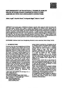
maximum of 40 iterations. If the SPA converges to a codeword the decoding finishes; otherwise, the LLR and received data are passed to array code decoder for 5 iterations. The new LLR's calculated by the array decoder are from iterative decoding procedure explained in Section III which is in principle different from SPA. These LLR's resulted from iterations of array code decoder can be used in different ways to help us improve the SPA decoder. These LLR values are not directly passed to SPA algorithm instead we tried a selection of these bits to initialize the SPA decoder. Those bits with high probability of being correct are assigned LLR of maximum possible value, e.g. 20. The other scenario is to choose the bits with probability of being correct, low LLR values. In this case, the bits are chosen based on the value of channel reliability factor for each Eb/N0. Then, the sign of the selected bits are flipped, assigned a large value, e.g. 20, and passed it to the SPA decoder. It has been noticed that there’s a good probability that in each case the SPA algorithm converges to a codeword. The result has been compared against serial concatenation of LDPC and BCH code. On contrary to proposed method the BCH code act as an outer code. We chose (1320, 1243) BCH code with 7 error correcting capability with roots in GF(211) as in [14]. The code rate of the overall system is reduced from 0.5 to 0.47, corresponding to a 0.26 dB rate loss. In Figs. 2 and 3 the simulation result for bit and block error performance of proposed algorithm and SPA has been shown. The result obtained here are the outcome of both bit-pinning and bit-flipping techniques which were used sequentially whenever primary stage decoder had been trapped. The effectiveness of this simple decoder is also confirmed by simulations, which shows no floor down to block error rate (BLER) of 10−8. We collected 18 error events at 2.6 dB, 5 error events at 2.7 dB and 2 error events at 2.8 dB.
Fig. 3 BLER performance of the Proposed Method for Conctenated Margulis Code (2640,1320) with Array Code (2745,2640)
V. CONCLUSION A serial concatenation of LDPC and array codes and a hybrid interactive decoding using both BCJR and SPA which exploits the bit-pinning and bit-flipping techniques were presented. The proposed HID algorithm targets potential trapping sets to improve the performance of LDPC codes with high error floors and is robust to any code with no available prior knowledge of trapping set structure. In the proposed configuration, exchange of extrinsic values between two decoders which are different in principle helps to avoid the trapping sets. Simulation results over AWGN channel showed that the concatenated LDPC/array code compensates the decrease in performance due to code rate loss and offers a significant improvement in the error floor performance. REFERENCES [1]
[2]
[3]
[4]
[5]
[6] [7]
Fig. 2 BER performance of the Proposed Method for Conctenated Margulis Code (2640,1320) with Array Code (2745,2640)
[8]
[9]
David J.C. MacKay and Radford M. Neal, "Near Shannon Limit Performance of Low Density Parity Check Codes," Electronics Letters, July 1996. Hongxin Song, R. M. Todd and J. R. Cruz, "Applications of low-density parity-check codes to magnetic recording channels," in IEEE Journal on Selected Areas in Communications, vol. 19, no. 5, pp. 918-923, May 2001 A. D. G. Biroli, M. Martina, and G. Masera, "An LDPC Decoder architecture for wireless sensor network applications," Sensors, vol. 12, no. 2, pp. 1529–1543, February 2012 R. Nabiei, M. Najafian, M. Parekh, P. Jančovič and M. Russell, "Delay reduction in real-time recognition of human activity for stroke rehabilitation," 2016 First International Workshop on Sensing, Processing and Learning for Intelligent Machines (SPLINE), pp. 1-5, Aalborg, 2016 P. M. Shah, P. D. Vyavahare and A. Jain, "Modern error correcting codes for 4G and beyond: Turbo codes and LDPC codes," Radio and Antenna Days of the Indian Ocean (RADIO), 2015, pp. 1-2, Belle Mare, 2015, Lin, S., & Costello, D. “Error Control Coding: Fundamentals and Applications,” Upper Saddle River, NJ: Prentice Hall, 2004. D. MacKay and M. Postol, “Weakness of margulis and ramanujan margulis low-density parity-check codes,” Electronic Notes in Theoretical Computer Science, vol. 74, 2003. T. Richardson, “Error floors of LDPC codes," in Proc. 41st Allerton Conf. Commun., Control, Computing, Allerton House, Monticello, IL, USA, Oct. 2003. T. Tian, C. Jones, J. Villasenor, and R. Wesel, “Construction of irregular ldpc codes with low error floors,” in Proc. of IEEE ICC ’03., vol. 5, pp. 3125–3129, May 2003.
[10] H. Xiao and A. Banihashemi, “Improved progressive-edge-growth (peg) construction of irregular ldpc codes,” IEEE Communications Letters, vol. 8, no. 12, pp. 715–717, Dec. 2004. [11] E. Cavus and B. Daneshrad, “A performance improvement and error floor avoidance technique for belief propagation decoding of LDPC codes,” in Proc. 16th IEEE International Symposium Pers., Indoor Mobile Radio Commun., vol. 4, pp. 2386-2390, Sept. 2005. [12] Chilappagari S.K., Sankaranarayanan S., Vasic B, ‘Error Floors of LDPC Codes on the Binary Symmetric Channel,”Proc. IEEE Conf. Comms ICC'06,pp.1089-1094, 2006. [13] Zhang Y. and RyanW.E., “Toward Low LDPC-Code Floors: A Case Study,” IEEE Transactions on Communications, vol. 57, pp.1566-1573, 2009. [14] Han Y. and Ryan Y. E. “Low-floor decoders for LDPC codes,” IEEE Transactions on Communications, vol. 57, pp. 1663 – 1673, June 2009. [15] Kang J., Zhang L., Ding Z., and Lin S., “A Two-Stage Iterative Decoding of LDPC Codes for Lowering Error Floors,” IEEE "GLOBECOM", 2008. [16] Ryan W.E., Lin S., “Channel Codes: Classical and Modern,” Cambridge Press, 2009 [17] D. M. Rankin and T. A. Gulliver, “Single parity-check product codes,” IEEE Transactions on Communications, vol. 49, pp. 1354–1362, Aug. 2001. [18] MacKay D., and Postol M., “Weakness of margulis and ramanujan margulis low-density parity-check codes,” Electronic Notes in Theoretical Computer Science, vol. 74, 2003. [19] Rosenthal, J., and Vontobel, P. O. “Constructions of LDPC codes using Ramanujan graphs and ideas from Margulis.” In Proceedings of the 38th Annual Allerton Conference on Communication, Control, and Computing, pp. 248, 2000.