142
IEEE MICROWAVE AND WIRELESS COMPONENTS LETTERS, VOL. 21, NO. 3, MARCH 2011
LTCC Packages With Embedded Phased-Array Antennas for 60 GHz Communications Dong Gun Kam, Senior Member, IEEE, Duixian Liu, Fellow, IEEE, Arun Natarajan, Member, IEEE, Scott Reynolds, Member, IEEE, Ho-Chung Chen, and Brian A. Floyd, Senior Member, IEEE
Abstract—A low-cost, fully-integrated antenna-in-package solution for 60 GHz phased-array systems is demonstrated. Sixteen patch antennas are integrated into a 28 mm 28 mm ball grid array together with a flip-chip attached transmitter or receiver IC. The packages have been implemented using low temperature co-fired ceramic technology. 60 GHz interconnects, including flip-chip transitions and via structures, are optimized using full-wave simulation. Anechoic chamber measurement has shown 5 dBi unit antenna gain across all four IEEE 802.15.3c channels, achieving excellent model-to-hardware correlation. The packaged transmitter and receiver ICs, mounted on evaluation boards, have demonstrated beam-steered, non-line-of-sight links with data rates up to 5.3 Gb/s.
Fig. 1. Package stack-up with integrated aperture-coupled patch antenna.
Index Terms—Antenna-in-package, millimeter-wave package, phased-array antennas, 60 GHz.
I. INTRODUCTION
T
HE unlicensed band around 60 GHz has emerged as a worldwide spectrum opportunity for the short-range wireless communication. One of the most attractive applications is uncompressed high-definition (HD) video streaming. Since line-of-sight (LOS) cannot be guaranteed in many indoor applications, techniques borrowed from phased-array radar systems have garnered much attention as a way of steering 60 GHz signals around obstacles. Recent advances in silicon technology have enabled a complex phased-array system to be downsized to a single chip [1]–[3]. In addition to device solutions, low-cost antenna and packaging solutions are important prerequisites for market success. The incorporation of phased-array antennas into a package is not a trivial task, because the influence of package-level coupling and mismatches degrades antenna bandwidth and radiation efficiency. Furthermore, any packaging solution must be suitable for mass production to capture high volume markets. In this letter, we present a low-cost, manufacturing-ready, easy-to-assemble antenna-in-package solution. Manuscript received September 27, 2010; revised December 05, 2010; accepted December 22, 2010. Date of publication February 10, 2011; date of current version March 11, 2011. D. Kam, D. Liu, A. Natarajan, and S. Reynolds are with the IBM T. J. Watson Research Center, Yorktown Heights, NY 10598 USA (e-mail:
[email protected]. com). H. Chen is with MediaTek Inc., Hsinchu, Taiwan. B. Floyd was with the IBM T. J. Watson Research Center, Yorktown Heights, NY 10598 USA and is now with the Department of Electrical and Computer Engineering, North Carolina State University, Raleigh, NC 27695 USA. Color versions of one or more of the figures in this letter are available online at http://ieeexplore.ieee.org. Digital Object Identifier 10.1109/LMWC.2010.2103932
II. PACKAGE DESIGN Low temperature co-fired ceramic (LTCC) has been popular in the RF packaging industry as it offers low-loss dielectrics, reliable multilayer implementation and ease of integrating embedded passives. In this work, LTCC’s excellent electrical properties at 60 GHz are key to meeting our antenna gain specifications. The loss tangent of the ceramic material used here was at 60 GHz, which is an order of magmeasured as nitude smaller than that of conventional PCB materials. The package stack-up is shown in Fig. 1. An air cavity is used beneath the aperture-coupled superstrate patch antenna to improve bandwidth and radiation efficiency [4]. Because the 60 GHz Tx [1] or Rx [2] IC is flip-chip attached to the bottom of the package, a coaxial via structure is implemented as shown in Fig. 2, [5], [6]. Due to the minimum via separation rule, the realized coaxial transition has large impedance, so two quarter wavelength transformers are used to reduce the impedance to . Although there is an increasing number of LTCC vendors who can yield much finer traces, minimum line width/space is used to better allow for manufacturing tolerance of . Although the Tx IC has 100- balanced output, the Tx package adopts the same single-ended 50- antenna as in the Rx package through a balun with loss because 100vertical transition is difficult to implement in this stack-up. More discussion on the antenna design can be found in [6]. One structure that had to be carefully optimized is the flipchip transition, as it directly affects the antenna bandwidth. Sensitivity analysis [7] was conducted in the early stages of chippackage co-design to optimize the joint. To summarize the results, a smaller pad, a larger pitch and a smaller bump diameter are generally preferred. Based on this, the diameter of flip. chip pads on both chip and package sides was set to for differential and The pad pitch was selected to be for single-ended high-speed signals while was selected for low-speed signals to minimize chip size. Once each
1531-1309/$26.00 © 2010 IEEE
KAM et al.: LTCC PACKAGES WITH EMBEDDED PHASED-ARRAY ANTENNAS FOR 60 GHZ COMMUNICATIONS
143
Fig. 2. 3-D view of antenna and feed line structures.
of these dimensions was set to its optimal value, equivalent circuit models were extracted from electromagnetic (EM) simulation so that on-chip impedance matching circuits could be designed. 60 GHz interconnects were designed to maintain both . Although intra- and inter-pair skews within this requirement in physical length is enforced by design rule checking in a CAD tool, it needs to be confirmed by 2.5-D simulation as propagation delay can vary due to meander bends. Once the layout was completed, full-wave simulation was conducted as final verification. Fig. 3 shows the 2-D view of an HFSS model for the Tx package, where 16 linearly-polarized phased-array antennas are arranged in a 4 4 rectangular array. Each of the 16 antennas is connected to an RF front-end and the signals from the 16 front-ends are combined in a four-stage binary combiner in the Tx/Rx IC (see [1] and [2] for detailed architectures). Fig. 4 shows the simulated antenna element gain for one particular direction (perpendicular to the package), with different curves showing the responses at the four different IEEE 802.15.3c channels. The gain of each antenna is computed with all other ports terminated with matched loads and mutual couis also pling among the antennas which is weaker than included. Antenna gain is dependent upon its location, showing gain across frequency. Since the single antenna pro[6] and the estimated insertotype shows peak gain of tion loss in the flip-chip transition and antenna feed is , the simulated results look reasonable. The element-to-element variation is a characteristic of finite arrays, which is, to some extent, inevitable. The bounded ground plane also perturbs the radiation pattern. Energy coming in along an antenna feed also excites a parallel-plate mode in addition to being coupled to a patch through an aperture. The parallel-plate mode progates toward the edge and then radiates into the air, interfering with the main radiation. However, it should be noted that this variation can still be fully equalized by adjusting the gain and phase settings of the Tx/Rx IC as long as it is systematic (i.e., predictable by simulation). III. PACKAGE CHARACTERIZATION Fig. 5 shows the fabricated LTCC package. Sixteen antennas and either the 60 GHz phased-array Tx or Rx IC have been fully ball grid array. Asintegrated in a 288-pin sembled packages were first tested in a socket evaluation board.
Fig. 3. HFSS model of Tx package with 60 GHz interconnects highlighted in yellow (package size = 28 mm 28 mm, antenna GND = 27 mm 27 mm).
2
2
Fig. 4. Simulated antenna element gain of Tx and Rx packages.
A high-speed pogo-pin test socket allowed the assembled packages to be screened quickly by monitoring synthesizer locking and the voltage and current consumption of each power supply. Screened packages were then soldered down to the evaluation board and measured in an anechoic chamber using an automated testbed fixture. Fig. 6 compares the simulated gain and measured power of the Rx antennas at one of the IEEE channels. For comparison purposes, both quantities have been normalized to their average value. Note that the simulation was performed at 60 GHz, which is slightly different from the IEEE channel 2 (60.48 GHz). Although the measurements also include the composite response of the chipset and the flip-chip transition, the measured results are in excellent agreement with simulations, validating both the complex EM model-based simulation methodology and the 60 GHz measurement setup.
144
IEEE MICROWAVE AND WIRELESS COMPONENTS LETTERS, VOL. 21, NO. 3, MARCH 2011
Fig. 5. LTCC package fully integrated with 60 GHz phased-array IC (288-pin ball grid array, 28 mm 28 mm).
2
link (NLOS) was then successfully established. Although the chipsets were manually pointed to an alternative beam direction in this demonstration link, an automated tracking algorithm is currently being developed. When using all 16 Tx and Rx elements, NLOS HD video links (1080p resolution) have been achieved with the total path-length of 20 m (using single reflection off a wall) [8]. IV. CONCLUSION An LTCC package fully integrated with sixteen antennas and a 60 GHz phased-array transceiver chipset has been demonstrated. Since the proposed package utilizes mainstream manufacturing and automated assembly processes, it paves the way for the market success of 60 GHz applications. Furthermore, since the overall antenna and package design approach is easily scalable to higher frequencies and/or larger arrays, the proposed antenna-in-package solution can be readily applied to other millimeter-wave applications, such as automotive radar and highresolution imaging systems. ACKNOWLEDGMENT
Fig. 6. Comparison of simulated and measured antenna gains of Rx package.
The authors wish to thank A. Valdes-Garcia, K. Toriyama, H. Noma, Y. Yamaji, T. Takatani, M. Gaynes, C. Baks, R. Morton, Z. Podpora, D. Dimilia, S. Gowda, D. Friedman and M. Soyuer of IBM, and J.-H. Zhan and J. Zhang of MediaTek, for their valuable contributions to this work. REFERENCES
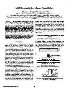
Fig. 7. Measured constellation for the four different IEEE channels, when the link is sending 5.3 Gb/s across 4 m Tx-Rx separation using single-carrier 16-quadrature amplitude modulation.
Fig. 7 shows the constellations for 5.3 Gb/s 16-QAM link with 4-m Tx-Rx separation (limited by lab size) and with only 6 Tx and 12 Rx elements activated, at approximately back-off. To demonstrate the beam-steering capability of the chipsets, an LOS link was initially established and then blocked using RF absorbing materials. Under the control of MATLAB algorithm and with the absorber still in place, a non-line-of-sight
[1] A. Valdes-Garcia, S. Nicolson, J.-W. Lai, A. Natarajan, P.-Y. Chen, S. Reynolds, J.-H. Zhan, and B. Floyd, “A SiGe BiCMOS 16-element phased-array transmitter for 60 GHz communications,” in IEEE ISSCC Tech. Dig., Feb. 2010, pp. 218–219. [2] S. Reynolds, A. Natarajan, M.-D. Tsai, S. Nicolson, J.-H. Zhan, D. Liu, D. Kam, O. Huang, A. Valdes-Garcia, and B. Floyd, “A 16-element phased-array receiver IC for 60 GHz communications in SiGe BiCMOS,” in IEEE RFIC Symp. Tech. Dig., May 2010, pp. 461–464. [3] E. Cohen, C. Jakobson, S. Ravid, and D. Ritter, “A thirty two element phased-array transceiver at 60 GHz with RF-IF conversion block in 90 nm flip chip CMOS process,” in IEEE RFIC Symp. Tech. Dig., May 2010, pp. 457–460. [4] J. Grzyb, D. Liu, U. Pfeiffer, and B. Gaucher, “Wideband cavity-backed folded dipole superstrate antenna for 60 GHz applications,” in Proc. IEEE Symp. Antennas Propag., 2006, pp. 3939–3942. [5] E. Pillai, “Coax via-a technique to reduce crosstalk and enhance impedance match at vias in high-frequency multilayer packages verified by FDTD and MoM modeling,” IEEE Trans. Microw. Theory Tech., vol. 45, no. 10, pp. 1981–1985, Oct. 1997. [6] D. Liu, H. Chen, and B. Floyd, “An LTCC superstrate patch antenna for 60 GHz package applications,” in IEEE APS/URSI Tech. Dig., Jul. 2010, pp. 1–4. [7] D. Staiculescu, J. Laskar, and E. Tentzeris, “Design rule development for microwave flip-chip applications,” IEEE Trans. Microw. Theory Tech., vol. 48, no. 9, pp. 1476–1481, Sep. 2000. [8] A. Natarajan, S. Reynolds, M. Tsai, S. Nicolson, J. Zhan, D. Kam, D. Liu, O. Huang, A. Valdes-Garcia, and B. Floyd, “A fully-integrated 16-element phased-array receiver in SiGe BiCMOS for 60 GHz communications,” IEEE J. Solid-State Circuits, vol. 45, no. 12, pp. 2757–2773, Dec. 2010.