LTL Formalization of BPML Semantics and Visual Notation for Linear Temporal Logic Marco Brambilla Dipartimento Elettronica e Informazione, Politecnico di Milano, Via Ponzio 34/5, 20133 Milano, Italy
[email protected]
Abstract. As the Web becomes a platform for implementing complex B2C and B2B applications, the need arises of extending Web conceptual modeling from data-centric applications to data- and process-centric applications. New primitives must be put in place to implement workflows describing business processes. In this context, new problems about process safety and verification arise. We study Web sites interacting with users or applications. We provide a formal data-driven model of the application, which can access an underlying database, as well as state information updated as the interaction progresses, and a set of user input. Against this Web application definition, we aim at verifying properties concerning the sequences of events, inputs, states, and actions, resulting from the interaction. In particular, we focus on workflow based properties, describing the execution flow of the tasks within the application. Such properties are expressed in linear or branching-time temporal logics. Since temporal logics properties are difficult to describe by a user, this work presents a visual approach that exploits and extends workflow notations (in particular, BPMN) for describing the rules to be verified. Some results from the same research group involved in this work establish under what conditions automatic verification of such properties is possible and provide the complexity of verification.
1
Contents Contents .......................................................................................................................... 2 1 Introduction............................................................................................................ 4 1.1 Overall view of the approach ........................................................................ 5 1.2 Organization of the work............................................................................... 6 2 Related work .......................................................................................................... 7 3 Formal specification of Web applications.............................................................. 9 3.1 Web application introductory description ..................................................... 9 3.2 Web application formal definition ................................................................ 9 3.3 Web page formal definition......................................................................... 10 3.4 Rules definition ........................................................................................... 11 3.5 Web application example ............................................................................ 11 3.6 Runs of a Web application .......................................................................... 13 4 Verifying linerar time temporal properties .......................................................... 15 4.1 Temporal logic basics.................................................................................. 15 4.1.1 Operators S and U ("since" and "until").................................................. 16 4.1.2 Metric tense logic.................................................................................... 16 4.1.3 Operator X (“next time”) ........................................................................ 17 4.1.4 Semantics of Tense Logic ....................................................................... 17 4.1.5 Branching time temporal logic................................................................ 17 4.1.6 Temporal Logic applications .................................................................. 18 4.2 Linear-time Temporal Logic formulae verification over runs..................... 18 4.3 Branching time properties ........................................................................... 20 5 Processes and workflow modeling....................................................................... 21 6 BPMN formalization using LTL formulae .......................................................... 25 6.1 Visual notation ............................................................................................ 25 6.1.1 Sequence ................................................................................................. 25 6.1.2 AND split ................................................................................................ 26 6.1.3 AND join................................................................................................. 26 6.1.4 OR split ................................................................................................... 27 6.1.5 OR join.................................................................................................... 27 6.1.6 XOR split ................................................................................................ 28 6.1.7 XOR join................................................................................................. 28 6.2 Notation summary ....................................................................................... 28 7 A visual notation for full LTL expressive power................................................. 31 7.1 Visual notation ............................................................................................ 31 7.1.1 Property................................................................................................... 31 7.1.2 Parenthesis .............................................................................................. 31 7.1.3 Before...................................................................................................... 31 7.1.4 Next......................................................................................................... 32 7.1.5 Globally / always .................................................................................... 32 7.1.6 Eventually ............................................................................................... 32 7.1.7 Until ........................................................................................................ 32
2
Boolean operators ................................................................................... 32 7.1.8 7.2 Notation summary ....................................................................................... 33 7.3 Usage examples........................................................................................... 34 8 Implementation .................................................................................................... 36 8.1 Tool overview ............................................................................................. 36 8.2 Tool capabilities .......................................................................................... 37 8.3 XML representation of diagrams ................................................................ 37 8.4 LTL formulae generation ............................................................................ 38 9 Conclusions.......................................................................................................... 41 10 References............................................................................................................ 42
3
1
Introduction
If we consider the broad set of interactive Web applications providing access to information as well as transactions, we can say that they are typically powered by databases. They have a strong dynamic component and are governed by protocols of interaction with users or programs, ranging from the low-level input-output signatures used in WSDL [31], to high-level workflow specifications (e.g., see [8, 6, 11, 30, 32, and 19]). One central issue is to develop static analysis techniques to increase confidence in the robustness and correctness of complex Web sites. This work outlines verification techniques for Web applications, and investigates the trade-off between the expressiveness of the Web application specification language and the feasibility of verification tasks. In our work we consider a Web application provided by an interactive Web server that posts data, takes input from the user, and responds to the input by posting more data and/or taking some actions. The Web site can access an underlying database, as well as state information updated as the interaction progresses. The structure of the Web page the user sees at any given point is described by a Web page schema. The content of a Web page is determined dynamically by querying the underlying database as well as the state. The actions taken by the Web site, and transitions from one Web page to another, are determined by the input, state, and database. The properties we wish to verify about Web applications involve the sequences of inputs, actions, and states that may result from interactions with a user. This covers a wide variety of useful properties. For example, in a Web application supporting an e-commerce application, it may be desirable to verify that no product is delivered before payment of the right amount is received. Or, we may wish to verify that the specification of Web page transitions is unambiguous, (the next Web page is uniquely defined at each point in a run), that each Web page is reachable from the home page, etc. To express such properties, we rely on temporal logic. Specifically, we consider two kinds of properties. The first requires that all runs must satisfy some condition on the sequence of inputs, actions, and states. To describe such properties we use a variant of linear-time temporal logic (LTL). This decision may arise some acceptance problem of such a complex formalism by the final user. Indeed, describing properties by means of temporal logic is a very technical task, that many users may not appreciate. For this reason, we propose a visual approach to specification of LTL properties. Our proposals are inspired by the standard notation developed for specifying workflow, like BPML/BPMN and others. In particular, the main original contribution of the work consists of two main aspects: (i) definition of formal semantics for the BPMN notation, a well known and established visual notation for workflow representation; (ii) proposal of a seamless and coherent extension of the BPMN notation for representing the full expressive power of Linear-time Temporal Logics. The already mentioned motivations of this work come from the fact that temporal logics properties are difficult to describe by a user, especially if he is involved in programming
4
and technology aspects of the Web application, and not so expert in mathematical and logical fields. Since this is the typical profile of a person that might be involved in specifications, design, development, and verification of Web applications, the full approach would risk not to be accepted by the users, because of the difficulties of the properties definition. The overall approach considers also another class of properties, involving several runs simultaneously. For instance, we may wish to check that for some run leading to some Web page, there exists a way to return to the home page. To capture such properties, we use variants of the branching-time logics CTL and CTL*. However, this paper does not address this class of problems. Some results identify classes of Web applications for which temporal properties in the cited temporal logics can be checked, and establish their complexity. Other works [] justify the choice of these classes, based on the fact that even slight relaxations of our restrictions lead to undecidability of verification.
1.1
Overall view of the approach
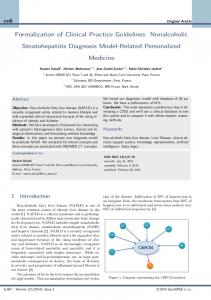
This section describes the overall result that we aim to achieve. It comprises the usage of several existing software tools, techniques and methodology, thus providing a global approach to design and verification of workflow-based Web applications. The approach is represented in Figure 1: the central element is a visual CASE tool that allows the design of BPMN workflow diagrams and the automatic generation of LTL formulae to be validated on a given formal specification of a Web application. Since the tool produces a XML representation of the workflow, several other translations can be implemented, simply programming new XSLT transformations. For example, it is possible to exploit the workflow diagram to generate a browsable HTML or even JSP prototype, which allows to immediately experience the resulting navigation of the specified process. Another interesting transformation automatically generates Web application diagrams according to existing modeling languages for the Web (e.g., WebML). To to apply automatic validation to the Web application, it must be formalized by a formal specification. This can be achieved by hands, or by implementing automatic translation of an existing model, like WebML. The validation itself can be achieved by using automatic verifier like SPIN, that can be applied to the formal specification of the Web application. The formulae to be checked can be LTL rules, automatically extracted by the BPMN representation of the site.
5
Manager
Richiesta di prestito
Validazione preliminare
Impiegato
Cliente
Start
+
End Approvazione finale
Controllo finanziario
+ Controllo sit. lavorativa
0, an input rule OptionsI(x) ← ϕI , W(x) where OptionsI is a relation of arity k, x is a k-tuple of distinct variables, and ϕI , W(x) is an FO formula over schema D ∪ S ∪ PrevI ∪ const(I), with free variables x. • For each state relation S ∈ S, one, both, or none of the following state rules: o an insertion rule S(x) ← ϕ +S,W (x), o a deletion rule ¬S(x) ← ϕ S,W (_x), where the arity of S is k, x is a k-tuple of distinct variables, and ϕ S,W (x) are FO formulas over schema D ∪ S ∪ PrevI ∪ const(I) ∪ IW, with free variables x. • For each action relation A ∈ AW, an action rule A(x) ← ϕ(x) where the arity of A is k, x is a k-tuple of distinct variables, and ϕ(x) is an FO formula over schema D ∪ S ∪ PrevI ∪ const(I) ∪ IW, with free variables x.
10
•
for each V ∈ TW, a target rule V ← ϕV,W where ϕV,W is an FO sentence over schema D ∪ S ∪ PrevI ∪ const(I) ∪ IW.
3.4
Rules definition
Since the formal definition of Web applications is not the main focus of this work, we present here only an intuitive definition of the rules involved in the specification: • The action rules of a Web page specify the actions to be taken in response to the input. • The state rules specify the tuples to be inserted or deleted from state relations (with conicts given no-op semantics, see below). If no rule is specified in a Web page schema for a given state relation, the state remains unchanged. • The input rules specify a set of options to be presented to users, from which they can pick at most one tuple to input (this feature corresponds to menus in user interfaces). At every point in time, I contains the current input tuple, and prevJ contains the input to J in the previous step of the run (if any). The choice of this semantics for prevJ relations is somewhat arbitrary, and other choices are possible without a_ecting the results. For example, another possibility is to have prevJ hold the most recent input to J occurring anywhere in the run, rather than in the previous step. Also note that prevJ relations are really state relations with very speci_c functionality, and are redundant in the general model. However, they are very useful when de_ning tractable restricitons of the model.
3.5
Web application example
To better describe the formalization of a Web application, we use as an example an ecommerce Web site selling computers online. New customers can register a name and password, while returning customers can login, search for computers fulfilling certain criteria, add the results to a shopping cart, and finally buy the items in the shopping cart.1 The following is a subset of the pages used in the example: HP (home page), RP (new user registration page), CP (customer page), AP (administrator page), LSP (laptop search page), PIP (search result index page), CC (cart contents page), MP (error message page). The following describes the home page HP which contains two text input boxes for the customer's user name and password respectively, and three buttons, allowing customers to register, login, respectively clear the input. Page: Home_Page (HP)
A demo Web site implementing this example, together with its full specification, is provided at http://www.cs.ucsd.edu/_lsui/project/index.html 1
11
Input: uname, password, clickbutton(x) Input Rules: Options@clickbutton(x) : = x="login" or x="cancel" or x="register" State Rules: error("bad user") : = not users(uname, password) and clickbutton("login") Target Webpages: HP, CP, MP, AP, NP Target HP : NP : CP :
Rules: = clickbutton("cancel"); = clickbutton("register"); = users(uname, password) and clickbutton("login") and (uname !="Admin") ; AP : = users(uname, password) and clickbutton("login") and (uname ="Admin") ; MP : = error("bad user")
Notice how the three buttons are modeled by a single input relation button, whose argument specifies the clicked button. This is a possible design choice, whereas other decisions could have been taken. The corresponding input rule restricts it to a login, clear or register button only. As will be seen shortly (Definition 2.3), each input relation may contain at most one tuple at any given time, corresponding to the user's pick from the set of tuples defined by the associated input rule. This guarantees that no two buttons may be clicked simultaneously. The user name and password are modeled as input constants, as their value is not supposed to change during the session. If the login button is clicked, the first state rule looks up the name/password combination in the database table user. If the lookup fails, the second state rule records the login failure in the state relation error, and the last target rule fires a transition to the message page MP. Notice how the “Admin” user enjoys special treatment: upon login, she is directed to the admin page AP, whereas all other users go to the customer page CP. Assume that the CP page allows users to follow either a link to a desktop search page, or a laptop search page LSP. We illustrate only the laptop search functionality of the search page LSP (see the online demo for the full version, which also allows users to search for desktops). Page: Laptop_Search (LSP) Inputs ISP : laptopsearch(ram, hdisk, display), button(x) Input Rules:
12
OptionsButton(x) := x=“search” or x=“view cart” or x=“logout” OptionsLaptopsearch(r,h,d) := criteria(“laptop”,“ram”,r) and criteria(“laptop”,“hdd”,h) and criteria( “laptop”, “display”, d) State Rules: userchoice(r,h,d) := laptopsearch(r, h, d) and button(“search”) Target Webpages: HP, PIP, CC Target Rules: HP := button(“logout”) PIP := ∃r∃h∃d laptopsearch(r,h,d) and button(“search”) CC := button(“view cart”)
Notice how the second input rule looks up in the database the valid parameter values for the search criteria pertinent to laptops. This enables users to pick from a menu of legal values instead of providing arbitrary ones.
3.6
Runs of a Web application
We next define the notion of “run” of a Web application. Essentially, a run specifies the fixed database and consecutive Web pages, states, inputs, and actions evolution. We define a run as follows: Def: a run over database instance D is an infinite sequence fhVi; Si; Ii; Pi;Aiigi_0, where: • Vi 2 W; Si is an instance of S, • Ii is an instance of IVi , • Pi is an instance of prevI, • Ai is an instance of AVi . In particular, the input constants play a special role. Their interpretation is not fixed a priori, but is instead provided by the user as the run progresses. We will need to make sure this occurs in a sound fashion. For example, a formula may not use an input constant before its value has been provided. We will also prevent the Web application from asking the user repeatedly for the value of the same input constant. Note that the state and actions specified at step i+1 in the run are those triggered at step i. This choice is convenient for technical reasons. As discussed above, input constants are provided an interpretation as a result of user input, and need not be values already existing in the database. Once an interpretation is provided for a constant, it can be used
13
in the formulas determining the run. For example, such constants might include name, password, credit-card, etc. A particular page of the site is the error Web page, which serves an important function, since it signals behavior that we consider anomalous. Specifically, the error Web page is reached in the following situations: (i) the value of an input constant is required by some formula before it was provided by the user; (ii) the user is asked to provide a value for the same input constant more than once; and, (iii) the specification of the next Web page is ambiguous, since it produces more than one Web page. Once the error page is reached, the run loops forever in that page. We call a run error free if the error Web page is not reached, and we call a Web application error-free if it generates only error-free runs. Clearly, it would be desirable to verify that a given Web application is error-free. As we will see, this can be expressed in the temporal logics we consider and can be checked for restricted classes of Web applications.
14
4
Verifying linerar time temporal properties
In this section we consider the verification of properties that must be satisfied by the runs of a Web application. Such properties are expressed using a variant of linear-time temporal logic, adapted from [13, 1, 28]. We begin by defining this logic, that we denote LTL-FO (first-order linear temporal logic).
4.1
Temporal logic basics
Linear temporal logic (LTL) is a field of mathematical logic that is able to talk about the future of paths. LTL is build up from proposition variables p1, p2, ..., the usual logic connectives ¬, ⇒, ∧, ∨ and the following temporal operators. LTL formulas are generally evaluated over paths and a position on that path. A LTL formula as such is satisfied if and only if it is satisfied for position 0 on that path. Unary operators: • N ϕ - Next: ϕ has to hold at the next state. • G ϕ - Globally: ϕ has to hold on the entire subsequent path. • F ϕ - Finally: ϕ eventually has to hold (somewhere on the subsequent path). Binary operator: • ϕ U ψ - Until: ϕ has to hold until at some position ψ holds. At that position ϕ does not have to hold any more. However one can reduce to two of those operators since the following is always satisfied: • F ϕ = true U ϕ • G ϕ = ¬ F ¬ϕ LTL can be shown to be equivalent to the first-order logic over one successor and the smaller relation, FO[S,