MAC Layer QoS Support for Wireless Networks of Unmanned Air Vehicles. IonuÄ Cârdei. ⧠... priority-based frame scheduling enable support for fair access and low ...... Radioâ, Phil Karn, RRL/CRRL Amateur Radio 9th Computer. Networking ...
Proceedings of the 37th Hawaii International Conference on System Sciences - 2004
MAC Layer QoS Support for Wireless Networks of Unmanned Air Vehicles
IonuĠ Cârdei♣
Sabera Kazi
Honeywell Labs 3660 Technology Dr., Minneapolis, MN 55418, U.S.A. {ionut.cardei, sabera.kazi}@honeywell.com
Abstract Mission-critical applications in wireless environments depend on a cross layer approach for Quality of Service. Dealing efficiently with variable link quality and dynamic topologies involves QoS integration at the link, network and transport layers interfaces. In this paper we present a new contention-based Medium Access Control protocol for wireless ad-hoc networks of unmanned air vehicles. A receiver-initiated access control protocol with sender scheduling provides the mechanisms to implement effective MAC-layer bandwidth allocation with support for ad-hoc scenarios. A variable RTS lead time procedure integrated with binary exponential backoff improves fairness and provides low access latency for critical data frames. A major protocol design factor is efficient operation under heavy load. Performance measurements from simulations indicate consistent performance and promising results.
1. Introduction Providing Quality of Service for bandwidth and delay is a critical element for supporting real-time and mission critical applications in emerging ad-hoc wireless networks. Link layer mechanisms play a key role for QoS in wireless environments prone to large variations in quality, and susceptible to interference, jamming and fading. In this paper we present a novel QoS-enabled Medium Access Control protocol for ad-hoc wireless networks, called Receiver-initiated Access Control with Sender Scheduling (RACSS). The RACSS protocol uses contention-based MAC with receiver-initiated sender
♣
scheduling for effective link-layer bandwidth allocation. An adaptive RTS lead time mechanism combined with priority-based frame scheduling enable support for fair access and low latency transmission. We introduce a new frame burst sender scheduling mechanism, Burst Mode Priority Sender Scheduling (BMPSS), that implements link-layer bandwidth allocation for active neighbor senders. The sender scheduling method for bandwidth allocation is appropriate for wireless networks of micro air vehicles, with primary missions performing situational awareness, surveillance and area monitoring. The vehicle communication system must be able to support QoS for both sensor-generated, high rate data streams (video/IR/acoustic) but also delay-critical short messages carrying mission control, telemetry or inter-vehicle coordination commands. QoS support for the Medium Access Control layer is active area of research. Most MAC QoS aware solutions that have been proposed use either a contention-free, scheduled access control such as Time Division Multiple Access (TDMA) or a contention-based medium access control. TDMA MAC protocols with QoS provisions include GSM [6] for cellular telephony, satellite communications [9] and Bluetooth in personal area networking [4]. The work in [14] introduces the FivePhase Reservation Protocol (FPRP) for MANETs, a TDMA protocol for ad-hoc networks, with an Alohabased slot reservation scheme. Most recent QoS solutions for contention-based MAC are extensions to IEEE 802.11 [1]. Currently under evaluation, the IEEE 802.11e standard [2] proposes QoS support for wireless LANs with a new Enhanced Distributed Coordination Function (EDCF) and a Hybrid
Contact author at tel: 612-9517487, fax: 612-9517438.
0-7695-2056-1/04 $17.00 (C) 2004 IEEE
1
Proceedings of the 37th Hawaii International Conference on System Sciences - 2004
Coordination Function (HCF) polling scheme. The work in [7] contributes two QoS extensions to IEEE 802.11, a distributed priority scheduling technique and a multi-hop coordination scheme that enables downstream nodes to adjust the priority of packets in transit to compensate for upstream delays. In [11] the authors propose extensive changes to the collision avoidance algorithm of IEEE 802.11 to implement a sophisticated bandwidth allocation mechanism, called DBASE, that supports both CBR and VBR traffic.
payload data and the delay-sensitive constraints raised by transmissions from navigation and collision avoidance.
This paper continues in Section 2 with the description of the protocol and its QoS mechanisms. Performance analysis, evaluation and simulation results for the RACSS MAC protocol are presented Section 3. The paper concludes in Section 4 with a summary and a discussion.
2.1. Traffic Characteristics and MAC Protocol Features
2. MAC Protocol Description The next few paragraphs describe the applicability of QoS in applications with micro air vehicles and the motivation for a new MAC protocol approach.
Existing MAC protocols for ad-hoc wireless networks with support for QoS do not fully address the specific requirements for extended range, throughput, overhead and delay constraints of MAV systems. Most MAC protocols have been built to suit generic scenarios with random mobility patterns and trade off overhead for fair medium access.
We have analyzed a set of MAV networking scenarios and derived a set of traffic characteristics and requirements shown in Table 1. Table 1. Traffic Characteristics And Requirements For MAV Networks
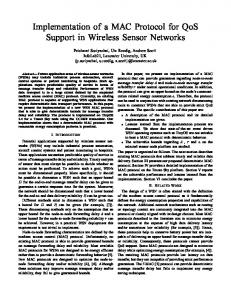
Primary applications for micro air vehicles (MAVs) include remote sensing, surveillance and battlefield situational awareness for small combat units (Figure 1). MAVs will deliver video, infrared and other sensor information to portable ground stations. real-time video & control extended op range multi-hop network
1
3 surveillance and targeting
2
UGV armed reconnaissance
fire control
enemy target
4
Figure 1. Micro air vehicle mission scenario Supporting competing QoS demands with a variety of attributes, requires a vertical cross layer approach for resource management and QoS, especially since micro air vehicles have very limited on-board resources. Adverse channel effects (multipath fading, jamming and cochannel interference) impair the effective transmission range when operating in dense foliage environments or in urban areas. In these scenarios, multiple vehicles will be used to form a multi-hop network to relay packets over line-of-sight links, while maintaining the expected delay and bandwidth requirements. One major design factor of our MAC QoS approach is the fact that the expected load on communication links is close to 100% whenever payload applications, especially video and radar, are active. The network must accommodate the high bandwidth requirements of
We designed the RACSS as a receiver-initiated MAC protocol with Quality of Service support and reliable transmissions based on link-layer retransmissions. Receiver-initiated medium access has been first proposed in the MACA-BI protocol [13]. The main QoS features backing QoS are receiver-initiated sender scheduling for effective link-layer bandwidth allocation and support for low latency transmissions enabled by an adaptive RTS lead time mechanism and priority-based frame scheduling. The main MAC protocol features are summarized in Table 2.
2.2.
Receiver-initiated Transmission
MACA-BI [13] introduced first the concept of collision avoidance with receiver initiated transmission. In contrast to IEEE 802.11 [1], MACA [8], MACAW [3], receiver-initiated MAC protocols rely on receivers to
0-7695-2056-1/04 $17.00 (C) 2004 IEEE
2
Proceedings of the 37th Hawaii International Conference on System Sciences - 2004
Table 2. RACSS Protocol Features
decide what node transmits, when and how much. This principle fits very well with communication patterns in micro air vehicle networks. For typical applications, high data rate demanding media/sensor streams flow down the network from remote vehicles to a central node for processing, with short delay-sensitive messages being transmitted between all mission participants. RACSS frame types derive from MACA-BI: -
Data – data frame. Fields: payload, length, priority, reliable (ACK is required from destination) and backlog - length of next frame for current destination.
-
Ready-To-Receive (RTR) – control frame: receiver computes a transmission schedule and sends RTR invitations to neighbor nodes for a burst transmission. The RTR frame piggybacks acknowledgement information in frame bursts.
-
Acknowledgement (ACK) – control frame: upon receiving the last data frame without errors from a burst, a node replies with an ACK frame. If the sender does not get back an ACK within a certain time, it will attempt retransmission.
-
Request-To-Send (RTS) – control frame: if a sender does not get an invitation (RTR) in time from a receiver, it will transmit an RTS frame. Upon reception of the RTS, the receiver may reply with an RTR invitation, or may defer and send an invitation to a different node.
Simulations have shown that the bandwidth overhead incurred from using ACKs to provide reliable communications is just 1%, while the additional delay is on average 700 microseconds. The relatively small overhead from ARQ pays well especially in environments where FEC cannot provide sufficient immunity to noise and interference. To relieve the overhead from the RTS – RTR – DATA – ACK handshake when a sender transmits consecutive
frames to the same destination node, we introduced support for burst communication. After each incoming data frame the receiver replies with an RTR, inviting the sender to continue transmitting data frames. When the receiver determines that the burst from a sender should be interrupted, it replies with a final ACK after the last burst frame. Starting with the sender’s initial RTS, a burst follows this frame sequence for reliable transmissions: RTS - RTR – DATA – RTR – DATA –…..– DATA – ACK, where italicized frames come from the receiver. RTR frames play two roles. First, they acknowledge correct data frame reception, and second, they keep the sender data frame flow open. In our current protocol implementation, if a data frame is received with unrecoverable errors, the receiver will transmit no RTR or ACK frame. The sender will timeout waiting for an acknowledgement and will reattempt transmission starting with a new RTS frame. For the purpose of discussing frame timing we assume that processing overhead for frame transmission and reception is negligible compared to the actual transmission time, discounting also the radio transceiver turn-around time, necessary to switch the radio from transmit to receive mode. After completing transmission of an RTS frame, the sender blocks, waiting up to a time Tbc for an RTR reply from the receiver: Tbc = 2 Tp + TRTR where Tp is the maximum propagation delay and TRTR is the transmission time for an RTR frame. If the sender timeouts waiting for RTR, it assumes its RTS did not reach the receiver, and will perform Binary Exponential Backoff (see Section 2.3) before retrying a new RTS to the receiver. Upon reception of an RTS frame, the receiver node transmits an RTR invitation to the sender and starts waiting for a time Tbd for the data frame, whose length is known from the RTS header: Tbd = 2 Tp + TDATA If the data frame does not arrive within Tbd, or is received with unrecoverable errors, the receiver switches to the idle state. In case the frame has been received correctly, the receiver replies with a new RTR, if the burst may continue, or with an ACK, to finish the burst for reliable data transmissions. The sender will therefore wait time Tbc for the reception of the ACK or RTR, before it timeouts and restarts the transmission process with an RTS frame, after performing backoff. For our RACSS implementation Tp = 50 µs, considering a maximum signal propagation distance under ideal conditions of 15 km and TRTR= TRTS = 256 µs, based on the control frame total size of 32 bytes, including an 8 byte preamble.
0-7695-2056-1/04 $17.00 (C) 2004 IEEE
3
Proceedings of the 37th Hawaii International Conference on System Sciences - 2004
Transmission of broadcast and multicast frames in the RACSS protocol is performed similarly to MACAW and 802.11.
2.3. Contention Resolution and Collision Avoidance For contention resolution, the RACSS MAC protocol uses a Binary Exponential Backoff (BEB) mechanism applied to packet sensing [8]. Carrier Sensing requires supplemental hardware resources and consumes extra power to keep the decoding stages active on the carrier frequency, even when the radio is idle. Therefore, the RACSS MAC protocol depends on the RTS – RTR handshake to prevent collisions through packet sensing. The work done for MACA-BI [13] and MACAW [3] indicates that with of error-free channels, there are no collisions between data frames, but only between control frames. Since RACSS control frames are very small (32 bytes, including preamble) compared to data frames, we expect the extra overhead from collisions between control frames to be low. To reduce the probability of repeated overlapping RTS transmissions, the RACSS protocol uses a Binary Exponential Backoff scheme. The time unit for backoff delays (time slot) is determined by the time needed to receive an invitation, including the RTS :
2.4.
Quality of Service Support
Our MAC protocol has an innovative combination of several mechanisms for providing support for link-layer Quality of Service and traffic differentiation. We start our description with two frame differentiation mechanisms, then continue with a receiver-driven sender scheduling mechanism called Burst-Mode Priority Sender Scheduling (BMPSS). 2.4.1.
Variable RTS Lead Time
The RACSS MAC protocol implements a technique based on variable RTS lead times to provide fair medium access for non-critical frames and low-delay access to critical frames. Similar in concept to the 802.11 Inter Frame Space, the RTS lead time is the time a sender must wait when the medium is available, before taking initiative and sending an RTS to the frame destination node. In our MAC protocol most contention occurs between competing RTS frames. The original BEB scheme reduces contention by delaying nodes with higher backoff counters. An RTS frame with a lower lead time has greater probability of being received at the receiver. We propose an adaptive scheme for the RTS lead time that takes into consideration the criticality of the data frame and medium access fairness.
Tslot = 2 Tp + TRTS + TRTS = 612 µs. In contrast with the 802.11 BEB version, our implementation resets the backoff counter to 0 when any of these events occurs while waiting for the blocking period to expire: -
sender receives any kind of frame intended for itself (control or data)
-
sender receives the final ACK for other node’s burst
-
maximum retry count is reached and the frame is dropped
802.11 and its variations reset the backoff counter (named “contention windows” in 802.11 documents) to 0 when a sender receives a CTS reply or successfully completes a DATA transmission and an ACK is received. Our implementation of BEB resets the backoff counter to 0 after the completion of a multi-frame burst of any node, not just the sender, reducing the medium access delay for all nodes to the penalties incurred by the variable RTS lead time algorithm.
Contention window
….
ACK
RTS TRTSwait0 = Tp
Critical frames
TRTSwait2
Recent inactive
TRTSwait1 Recent active
Figure 2. RTS Frame Lead Time RACSS defines three values for the RTS lead time (Figure 2). The critical RTS lead time, equal to the maximum propagation delay, Tp, is used for time-critical transmissions, such as for inter-aircraft collision avoidance coordination or weapon commands, TRTSwait0 = Tp. The regular RTS lead time, for normal (non-timecritical) traffic, is a randomly distributed number of time slots, Tslot. More time slots are used when the sender has completed a successful transmission in the recent past (Tw1 = 10 ms): TRTSwait1 = U(0, rtsWaitSlots) ⋅ Tslot If the sender has not communicated within Tw1, the RTS lead time is set to TRTSwait2 = U(0, rtsWaitSlots /2) ⋅ Tslot
0-7695-2056-1/04 $17.00 (C) 2004 IEEE
4
Proceedings of the 37th Hawaii International Conference on System Sciences - 2004
where rtsWaitSlots is a protocol parameter. Thus, nodes that have been waiting longer for access are more likely to be assigned a lower number of time slots than nodes that have been communicating recently. RTS frames for time-critical data are assigned the minimum lead time equal to Tp, preempting all other transmissions. This scheme can be easily be extended for more priority levels, considering also fairness.
not perform as well in environments with hidden terminals that require support for ad-hoc topologies with multi-hop routes. In these scenarios, TDMA MAC protocols must employ a coordination protocol that implements distributed time slot allocation. The FPRP MAC protocol [14] uses such an approach for slot reservation. A bandwidth allocation solution for contention-based MAC, implemented for IEEE 802.11 is described in [11].
2.4.2.
With our contention-based MAC protocol with receiver initiated transmission, we introduce a lightweight and simple solution for bandwidth allocation based on sender scheduling, that supports ad-hoc topologies and delay-sensitive transmissions. The mechanism for directing sender scheduling is based on the control frame handshake, centered on the Ready-To-Receive frame. If node A knows that nodes B and C have data frames queued up for node A, and that C’s frames are more urgent, A will send an RTR invitation to node C first. The information on pending traffic and its QoS attributes would come from higher layers.
Local Priority Frame Scheduling
RACSS uses a priority number to select internally the frame to transmit from its internal queues. To break a tie, the oldest frame is selected. Priority based transmission scheduling provides frames that carry critical information access to the medium with less queuing delay, reducing their total communication latency. The 8 bit priority field from the MAC frame header supports up to 256 priority levels and can be integrated with priority schemes from a higher layer, such as IP DiffServ [5]. 2.4.3.
Frame Filtering
For sensor information communications, frames received after their deadline expires are useless. For realtime video display and analysis only the most recent frames are of interest. Similarly, voice or acoustic data frames loose their value after a maximum delay or when more recent frames become available. The RACSS MAC header has a time-to-live field that indicates the remaining lifetime for a data frame in milliseconds. The ttl for a frame is set by higher layers, according to mission QoS information. Whenever a frame arrives at the MAC layer (from a higher layer), the ttl is reduced by the expected queuing time and the transmission time. If ttl < 0, the frame will be dropped immediately, since it would not reach its destination in a timely manner, anyway. Right before a frame is sent to the physical layer, its ttl is updated again, to reflect the actual time spent in the MAC frame queue. A frame with negative ttl will be dropped before transmission. This filtering mechanism saves buffer space and medium time, effectively improving QoS for data frames that can be delivered in time or have no deadline. Setting the ttl field to 0 indicates the scheduler that filtering is not required for a frame. 2.4.4.
Receiver-initiated Sender Scheduling
In this paper, we propose an efficient mechanism for link-layer bandwidth allocation based on Burst Mode Priority Sender Scheduling. In the RACSS protocol, immediate medium access is arbitrated by the RTS lead time and the BEB mechanisms, while priorities determine the frame ordering. In centralized wireless networks, bandwidth allocation and medium access can be tightly managed with a TDMA link layer protocol. TDMA does
The sender scheduling algorithm is initiated with a list of bandwidth weights for each neighbor. A weight defines the fraction of total channel capacity that should be allocated to a specific sender. A mechanism derived from the Deficit Weighted Round Robin IP packet scheduling [12] is used to compute the sender bursts. A frame burst consists of several back-to-back data frame transmissions from the same sender. After each data frame reception, the receiver sends a new invitation with an RTR frame and piggybacks acknowledgement information. When the receiver decides to terminate the current burst, it replies with an ACK message, instead of another invitation. The receiver may select to switch to another sender (including itself) or just relinquish medium control and let other nodes transmit. During initialization, or whenever the bandwidth allocation changes, the receiver computes a new sender schedule S = , consisting of medium transmission time ti and the number of bursts allocated to each sender, bi. The receiver selects the next sender to be the node with the highest priority traffic pending. The priority for a sender is considered to be the most recent received. If more senders have the same high priority, the receiver cycles through them in a round robin way. In typical scenarios with multi-hop paths, local traffic forwarders act as sinks for upstream nodes. Their bandwidth allocation is coordinated through per-node time division. D = , where j =1,..., n, and n is the number of “local sink nodes” (receivers) in the network.
0-7695-2056-1/04 $17.00 (C) 2004 IEEE
5
Proceedings of the 37th Hawaii International Conference on System Sciences - 2004
The allocation fj for each receiver is computed such that interference is kept low and spatial reuse is maximized. How to compute is outside the scope of this paper. The transmission time at a receiver node is further divided into equal size scheduling cycles. fj gives the actual tine in a second that a particular receiver can schedule sender transmissions. Sender i is thus allocated a time ti for transmission in each second by a receiver node j: ti = wi fj During a scheduling cycle, all recent traffic participants are invited to transmit in order of their priority, until they exhaust the maximum burst transmission time. For instance, in Figure 1 the ground station node allocates 50% transmission time to in-range relays 1 and 2, and 2 further allocates another 45% of transmission time to vehicle 3 and 5% to the mobile node 4.
receiver will reply with a new RTR invitation. When the burst time or the cycle time is exceeded, the receiver will stop sending a new RTR to that sender. Instead it will select another node (or itself) that has time left for transmissions in the current scheduling cycle. Another case when the receiver switches to a different sender is when the incoming packet indicates that the sender has no more data to transmit. The steps executed by BMPSS for an incoming DATA frame are listed below, in Figure 4: eventhandler EventDATAReceived(frm) // update scheduler state and select next //sender: nextSender = ScheduleOnReception(frm) if nextSender = this node initiate transmission from this node // select frame from out queue and send RTS return else if nextSender != frm.source // burst interrupted, send ACK, if required: if frm.reliable == 1 send ACK to frm.source endif if nextSender != NULL send RTR invitation to nextSender else defer transmission, let other nodes transmit endif endif
The transmission order is not strict. If a receiver gets an RTS from a node that is out of order, or without an allocation, it will allow the sender to complete a burst, and it will record its transmission time. Next scheduling cycle that node will have its share reduced accordingly, so that overall, all nodes use their fraction of the allocated transmission time.
Figure 4. Scheduler activation by the DATA reception event handler
The schedule setup algorithm is listed in Figure 3: proc ScheduleSetup(w: bandwidth fraction array, sc: schedule cycle, f: receiver time fraction maxBS :maximum burst size) for each neighbor node i with w[i] > 0 : // time allocated to sender I // during one scheduling cycle: cycleTime[i] = w[i] * sc * f // burst count for sender i // during a cycle: burstCount[i] = floor(cycleTime[i] / maxBS) endfor return cycleTime, burstCount
Figure 3. Sender scheduler setup If the total weighted sum of time allocations is less than 1, the remaining medium time is left unused by the receiver. The BMPSS algorithm includes in its schedule transmissions from the local node. The sender schedule is activated at a receiver when a frame is received from a neighbor. The receiver updates the time the sender spent during the current scheduling cycle. In case the sender has more data frames intended for the receiver and has not exceeded its cycle time, the
The BMPSS sender selection is listed below, in Figure 5: function ScheduleOnReception( frm: incoming frame, f: receiver time ) nextSender = NULL // time left to schedule tx ? if receiver time fraction f depleted return // yes, attempt to schedule sender: if frm.backlog > 0 // sender has more data for this receiver // update time left for sender // in current cycle: cycleTime[frm.source] = cycleTime[frm.source] – frm transm.time // update time used by sender in current // burst: burstTime[frm.source] = burstTime[frm.source] + frm transm.time // transmission time for the next frame from // sender: nextFrmTime = transmission time for a frame with frm.backlog bytes
0-7695-2056-1/04 $17.00 (C) 2004 IEEE
6
Proceedings of the 37th Hawaii International Conference on System Sciences - 2004
// if enough time left in this cycle and // burst: if cycleTime[frm.source] – nextFrmTime >0 AND burstTime[frm.source] + nextFrmTime < maxBurstSize
domain. The MAC protocol parameters are listed in Table 3. Table 3. MAC simulation parameters.
// current sender can keep transmitting: nextSender = frm.source endif endif
Parameter Data rate
Value 1 Mbps
Parameter Queue size
Value 8 kB
MTU
1000 B
RTSWait
6 slots
if nextSender == NULL // select next sender among nodes with // nonzero allocation (including receiver // node): nextSender = SelectSender()
Max range
10 km
Schedule cycle
200 ms
Max retry
16
Max burst
20 ms
// setup a new burst: burstTime[nextSender] = 0 endif return nextSender
Figure 5. Sender scheduling code After executing ScheduleOnReception() the receiver sends an RTR to the nextSender node. If nextSender is the receiver node itself, the receiver will initiate a transmission with an RTS, while keeping the receiver schedule updated just as it does for other nodes. The SelectSender() function selects the highest priority sender with a nonzero allocation that has transmission time left available in the current scheduling cycle. If a node does not reply to an RTR invitation, the receiver will skip it for the current scheduling cycle. This prevents precious medium time being wasted on waiting frames from nodes that have gone out of range or have no other data pending for the current receiver node. The BMPSS mechanism is opportunistic, in the sense that a sender node transmitting to an idle receiver will be allowed to transmit an entire burst, even if it is out of order. The sender schedule is activated on a node when it receives data frames. Thus, when a network is lightly loaded, receivers do not waste medium time sending unnecessary invitations, just to keep with the round robin sender ordering. Scheduling senders ordered on priority of their data provides additional support for low latency communication for critical data.
3. Protocol Performance Evaluation To evaluate the performance of the RACSS MAC protocol, we implemented the protocol engine and several scenarios in the OpNet network simulator [10]. Our initial measurements focus on protocol performance in static scenarios with variable load. A topology with 10 wireless nodes was defined, with all nodes in the same collision
count
time
The first series of measurements describe protocol performance depending on traffic load. The aggregate source traffic load is varied from 10% to 110%, where 100% corresponds to the total channel capacity, 1 Mbps. MAC drops excessive frames. The generated traffic mimics an application with MAVs transmitting sensor data to a ground station node, and the GS sending short periodic control frames to each vehicle. In Figure 6 we show the achieved goodput, throughput and the relative overhead depending on the aggregate traffic source load. The network reaches its maximum goodput (80.6%) when the sources generate more than 900 kbps (90% capacity). The overall network throughput, including goodput and all control frames is also limited at 91% of total channel capacity. A key metric for MAC protocol performance is the medium access delay. This measures the time spent by a frame within MAC buffers before transmission starts. It is the sum of queuing delay and the channel reservation delay. The medium access delay dependency on the aggregated offered goodput is illustrated in Figure 7. The maximum achievable goodput in the network is 80.6% from channel capacity (1 Mbps). As expected in networks with contention-based MAC, the delay rises at high load (after goodput exceeds 70% from capacity). The 8 frame MAC transmission queue capacity and the round-robin transmission scheduling cause the average delay to exceed 0.5 s before traffic load reaches the 80.6% plateau. The overhead is measured relative to the total network throughput and decreases slightly, from 14.5% down to 12%, when the source load grows from 10% to 110%. Since the measured overhead includes transmission for all control frames and does not grow with network load, our numbers indicate that contention and collisions do not penalize the medium access delay as the network load increases.
0-7695-2056-1/04 $17.00 (C) 2004 IEEE
7
Proceedings of the 37th Hawaii International Conference on System Sciences - 2004
10% 8% 6% 4% 2% 0%
Source Load (%)
35% 30% 25% 20% 15% 10% 5% 0% -5%
Throughput
Goodput
Relative Traffic Overhead
Deviation from weight
12%
Channel Capacity (%)
14%
Relative Traffic overhead (%)
16%
100% 90% 80% 70% 60% 50% 40% 30% 20% 10% 0%
10 % 20 % 30 % 40 % 50 % 60 % 70 % 80 % 90 % 10 0% 11 0%
Channel Utilization
sender scheduling introduces more delay for 9’s transmissions, while contending with all other nodes.
GS
1
2
3
4
5
6
7
8
9
-10% Node ID
Figure 6. Goodput, throughout and relative overhead depending on source traffic load.
Schedule Weight
Measured utilization
Deviation from schedule
Figure 8. Schedule allocation weights, measured utilization and deviation from schedule. Medium Access Delay (s)
0.6 0.5 0.4 0.3 0.2 0.1 0 0%
20%
40%
60%
80%
100%
Aggregate Measured Goodput (% channel) Average Delay
The performance of priority-based sender scheduling is illustrated in Table 4. We ran the 10 node scenario with one vehicle node with critical priority. The table shows how medium access delay improves compared with the scenario with best effort priority. The average, maximum delay and the jitter are more than twice shorter for higher priority traffic. Also, the goodput improves 2.17 times for critical frame transmissions. The flexible sender scheduling mechanism does not strictly enforce the initial allocation, thus allowing capacity to be diverted to critical nodes on demand.
Stdev
Figure 7. Evolution of the medium access delay with the offered aggregate network goodput. The effectiveness of the sender scheduling mechanism is shown in Figure 8. The ground station node assigns each node an allocation weight that defines the fraction of channel capacity a sender is supposed to use for its transmissions. We measured the effective node transmission throughput for the (10%, 5%, 5%, 5%, 10%, 10%, 10%, 10%, 5%, 30%) allocation and the deviation from allocation. The ground station shows the best compliance to the desired schedule, only 0.02%, since it does the transmitter scheduling. The highest deviation from schedule (5.49%) is experienced by the sender with the highest allocation (30%), achieving lower throughput than scheduled. Meanwhile other senders with lower allocations consistently receive more capacity from the ground station. The deviation is caused by the source traffic definitions. Node 9 generates 10000 byte long messages that are fragmented in 1000 byte frames. The 20 ms maximum burst size and the preemptive nature of
Average (ms) Min (ms) Max (ms) Stdev (ms)
Best Effort 493.549 2.900 1391.911 298.434
Critical Improvement 235.445 2.10 0.568 5.11 595.472 2.34 127.308 2.34
Table 4. Delay performance for best effort and critical frame transmission. Work on performance evaluation with simulations of mobile ad-hoc topologies is under progress. Results will be reported in a later publication.
4. Conclusion This paper presents the design and performance evaluation of a MAC protocol for wireless networks of micro unmanned air vehicles. Applications with MAVs have specific requirements for communication QoS with emphasis on low overhead under heavy sensor transmission load. Motivated by the need of multi-hop adhoc network support and constraints on power, range,
0-7695-2056-1/04 $17.00 (C) 2004 IEEE
8
Proceedings of the 37th Hawaii International Conference on System Sciences - 2004
volume and processing resources, we designed a new contention-based MAC protocol that implements a sender scheduling mechanism for effective and low overhead link-layer bandwidth allocation for nodes within communication range. The scheduling scheme can be extended to multi-hop topologies by a network-layer configuration protocol. Priority frame scheduling with delay-sensitive filtering and a variable RTS lead time scheme integrated with the Binary Exponential Backoff algorithm provide low medium access delay and fairness. We have evaluated the protocol performance with simulations in OpNet and the results have shown promising results. Our current work on RACSS involves refining and evaluating QoS performance, under TCP/IP and DiffServ.
[14] “A Five-Phase Reservation Protocol (FPRP) for Mobile Ad Hoc Networks”, Chenxi Zhu, M. S. Corson, in Wireless Networks, Kluwer Academic Publishers, Volume 7 , Issue 4 (August 2001)
References [1] http://grouper.ieee.org/groups/802/11/ [2] http://grouper.ieee.org/groups/802/11/Reports /tge_update.htm [3] ”MACAW: A Media Access Protocol for Wireless LANs”, V. Bharghavan, A. Demers, S. Shenker, L. Zhang, SIGCOMM '94 , September 1994, pp. 212-225
[4] http://www.bluetooth.com [5] http://www.ietf.org/html.charters/diffserv-charter.html [6] “GSM Switching, Services, and Protocols”, Joerg Eberspaecher, Hans-Joerg Voegel, Christian Bettstetter. John Wiley & Sons; 2nd edition, 2001 [7] “Distributed priority scheduling and medium access in ad hoc networks”, Vikram Kanodia, Chengzhi Li, Ashutosh Sabharwal, Bahareh Sadeghi, Edward Knightly, in Wireless Networks, Kluwer Academic Publishers, Volume 8, Issue 5 09/2002 [8] “MACA - A New Channel Access Method for Packet Radio”, Phil Karn, RRL/CRRL Amateur Radio 9th Computer Networking Conference, pp. 134-140, ARRL, 1990 [9] “Satellite Communications Systems: Systems, Techniques and Technology”,Gérard Maral, Michel Bousquet. John Wiley & Sons; 4th edition 2002 [10] http://www.opnet.com [11] “A Bandwidth Allocation/Sharing/Extension Protocol for Multimedia Over IEEE 802.11 Ad Hoc Wireless LANs”, Shiann-Tsong Sheu, Tzu-Fang Sheu, IEEE Journal on Selected Areas in Communications 19(10): 2065-2080, 2001 [12] “Efficient fair queueing using deficit round robin”, M. Shreedhar, G. Vargese, in Proc. ACM SICOGMM'95, pages 231--242, 1995 [13] “MACA-BI (MACA by invitation). A Wireless MAC Protocol for High Speed Ad hoc Networking”, Fabrizio Talucci and Mario Gerla, Proceedings of IEEE ICUPC '97
0-7695-2056-1/04 $17.00 (C) 2004 IEEE
9