MAC protocol are proposed for supporting various IP traffic types and service classes, whilst providing end-to-end QoS. Fig. 2. MAC frame for HiperLAN2.
MAC Protocol for Supporting QoS in All-IP HiperLAN2 Christos E. Politis, Rahim Tafazolli University of Surrey Centre for Communication Systems Research Guildford, GU2 7XH, Surrey, UK Tel.: +44 1483 683463, FAX: +44 1483 686011 {c.politis, r.tafazolli}@eim.surrey.ac.uk Abstract -- The demand for high-speed Internet access and the emergence of multimedia applications are leading towards a new area of broadband wireless networks. This paper focuses on HiperLAN2 air-interface standard based on an “all-IP” network architecture. An appropriate QoS framework is proposed, based on which, classification and scheduling mechanisms of traffic classes are investigated. These could be considered as potential enhancements and compliments to the MAC protocol of HiperLAN2 for providing end-to-end QoS.
common part and a service specific part, which consists of several Service Specific Convergence Sub-layers (SSCS). The user plane of the common part is further subdivided into the Common Part Convergence Sublayer (CPCS) and the Segmentation and Reassembly (SAR) sublayer (Fig. 1) [3]. The CL has two main functions, adapting the service request from HLs to the service offered by the DLC layer and secondly to adjust the HL variable size packets to the DLC SDU (Service Data Unit) fixed size. C o n tro l P la n e
I. INTRODUCTION
U s e r P la n e
H ig h e r L a y e rs
HiperLAN2 (HIgh PERformance LAN) operates in the unlicensed 5 GHz frequency band, which has been allocated for wireless LANs. HiperLAN2 (H2) systems can be deployed in offices, classrooms, homes, factories, hot spot areas and potentially wherever radio transmission is an efficient alternative or a complement to wired technology. In contrast to the IEEE 802.11 wireless Ethernet technology, H2 is connection oriented. Connections can be assigned different levels of Quality of Service (QoS). This QoS support allows for the transmission of a pot pouri of technologies and services, e.g. voice, data, video at very high bit rates (>10 Mb/s). The ETSI (European Telecommunications Standards Institute) HiperLAN2 architecture comprises of the Physical (PHY) layer, the Data Link Control (DLC) layer and the Convergence Layer (CL). The Convergence layer performs specific functions between the DLC layer and the network layer. These functions are introduced, in order to provide connectivity between the PHY, DLC layers of the H2 and the other access networks, such as IP, ATM and UMTS. The physical layer of HiperLAN2 is based on the signal modulation Orthogonal Frequency Division Multiplexing (OFDM) with several sub-carriers and forward error correction schemes, which can support variety of channel configurations [1]. The DLC/MAC layer is presented in details in section II. The H2 Convergence layer, functions as an adapter between the DLC and higher layers (e.g. IP, application layers). Two types of CLs have been specified by ETSI BRAN (Broadband Radio Access Networks), a ATMcell based CL and a packet based CL. This paper mainly focuses on the packet based CL, which offers services to higher layers (HL) that use packets or frames of variable size or fixed size (e.g. Ethernet and/or the IP suite). The packet based CL is divided into two main parts, a
C L (S S C S ) IP S e rv ic e S p e c ific C o n v e rg e n c e S u b la y e r (S S C S )
C o m m o n P a r t P a c k e t -b a s e d C L ( C P C S ) S e g m e n ta t io n a n d R e - a s s e m b ly ( S A R )
C L (C P C S ) D L C C trl S A P
D LC U ser SA P
DLC RLC RRC
AC
EC
DCC
MAC PHY S A P : S e rv ic e A c c e s s P o in t R R C : R a d io R e s o u rc e C o n tro l
(O F D M )
A C : A s s o c ia tio n C o n tro l D C C : D L C C o n n e c tio n C o n tro l
Fig. 1. HiperLAN2 protocol stack (Access Point and Mobile Terminal). In the H2 cellular system, the AP (Access Point) is the controller for each formed radio cell that covers certain geographical areas. H2 supports transmission in the uplink (UL), downlink (DL) as well as direct link (DiL) - for ad hoc configuration. II. H2 MAC PROTOCOL The H2 DLC layer consists of the Medium Access Control (MAC) function, the Error Control (EC) function and the Radio Link Control (RLC) function. It is divided into the user data transport functions and the control functions. For the H2, a centrally controlled DLC layer is selected, in other words the access point decides how the resources are allocated in a MAC frame. The MAC protocol is a centrally scheduled TDMA/TDD (Time Division Multiple Access/Time Division Duplex) scheme. Each MAC frame has a fix duration of 2ms and consists of several phases. Important entities of the MAC frame are the logical and transport channels. A logical channel is a generic term
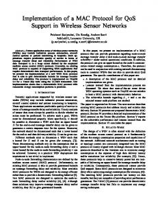
for any distinct data path and it is mapped onto different transport channels. The transport channels are the basic elements that construct the PDU (Protocol Data Unit) trains. Transport channels describe the basic message format. The MAC decomposition to its child entities is bullet-listed here and a visual representation is shown in Fig. 2 [2].
MAC Frame (2 ms) Varying borders
Broadcast Phase
BCCH1
BCCH
FCCH1
Downlink (DL) Phase
Uplink (UL) Phase
Random Access Phase
FCCHN
RCH1
RCHN
Random Access Data
BCH
FCH
ACH
Broadcast Data
Broadcast phase: This phase carries the BCCH (Broadcast Control CHannel) and the FCCH (Frame Control CHannel), which are mapped onto the BCH (Broadcast CHannel) and FCH (Frame CHannel) respectively. The BCH transmits control information in each MAC frame and to all MTs (Mobile Terminals). The FCH carries an exact description of how the current MAC resources have been allocated to the UL/DL. This phase also includes the ACH (Access feedback CHannel), which provides information on access attempts made by MTs in the RCH (Random access CHannel) of the previous MAC frame. Downlink phase: It consists of SCH (Short CHannels) and LCH (Long CHannels). During this phase, control information and user data are transmitted from the AP to MTs. The information is assembled in groups of variable length, called cell trains. Each cell train is unique for a correspondent MT. Uplink phase: In this phase (same structure as DL), control information and user data are transmitted from the MTs to the AP. Random Access phase: This phase carries the RCHs.
The DL, UL phases consist of two types of DLC PDUs (see Fig. 2): long PDUs (LCH) and short PDUs (SCH). The LCH PDUs carry mainly the payload of the connections. Their size is 54 bytes, whereby 48 bytes are allocated for the payload and the rest (6 bytes) are used for DLC headers. At the same time, the SCH PDUs contain generally control data (e.g. ARQ) and their size is 9 bytes. SCH PDUs are also used by MTs to request resources (RR) for a particular connection in the next MAC frame. The RR can either be transmitted during the UL phase in SCH PDUs or in the RCH in competition with other MTs. The structure of each cell train is cached in the FCH, which serves as a directory for UL and DL phases. The FCH PDU carries a list of Resource Grant Information Elements (RG-IE), each defining a cell train of one MT, either UL or DL. The RG-IE is organized in blocks of 8 bytes. The block consists of the IE addressing the particular MT by its MAC-id and determining the location of the cell train within the MAC frame by the start pointer field. The FCH PDUs are segmented in groups of constant length each protected individually by a CRC (Cyclic Redundancy Check), in order for the receiver to decode early the relevant information contained in them. In the following sections, the enhancements to H2 MAC protocol are proposed for supporting various IP traffic types and service classes, whilst providing end-to-end QoS.
DL1
DLK
SCH
SCH
UL1
LCH
ULK
LCH
SCH
LCH
DL, UL control & user data
BCCH: Broadcast Control CHannel FCCH: Frame Control CHannel BCH: Broadcast CHannel FCH: Frame CHannel
ACH: Access feedback CHannel SCH: Short transport CHannel LCH: Long transport Channel UL: Uplink Control & User data
DL: Downlink Control & User Data RCH: Random Access CHanne1 RR: Resource Request RG: Resource Grand
Fig. 2. MAC frame for HiperLAN2. A small introduction to the H2 CL for IP follows. A. IP Support The H2 Convergence layer functions as an adapter between the DLC and higher layers (e.g. network layerIP). Here, IP packets are transferred to the CL layer through the CL Service Access Point (SAP). At this point, packets are “stamped” with information about their length, source and destination addresses and their QoS parameters. The target of the address management function in the H2 convergence layer is to maintain a mapping between the local link layer addresses and the addresses sent by the IP wireless interface. This can be accomplished by using other wireless interfaces’ addresses (i.e. IEEE802.11b) as static hardware addresses [4]. At the same time, implementing end-to-end QoS requires cooperation at all protocol levels, however in this paper the mapping of the IP (Network) layer QoS to the DLC QoS is the main objective. The DLC entity of interest is the MAC one. Thus, suitable QoS techniques are introduced for the management of the scarce radio resources. This approach is presented in the rest of this paper, examining effective classification and scheduling algorithms. III. QOS SUPPORT AND SCHEDULING The basic way to provide QoS is by giving one user priority over another, and/or to control the bandwidth usage of certain users so that a pre-assigned QoS can be assured. Furthermore, in order to support the variety of services, it is necessary to develop a QoS mechanism/framework that can support multiple services and traffic classes. These traffic classes will classify packet streams according to their real-time needs. Four traffic classes are selected, in close relation to the UMTS QoS Classes defined in [20] and used in [5, 6], the following:
Conversational,
Streaming,
Interactive,
Background.
The main distinguishing factor between these QoS classes is how delay sensitive the traffic is: Conversational class is meant for traffic which is very delay sensitive while Background class is the most delay insensitive traffic class. Conversational and Streaming classes are mainly intended to be used to carry real-time traffic flows. The main divider between them is how delay sensitive the traffic is. Furthermore, Conversational class supports mainly bi-directional traffic with uplink and downlink QoS provisioning. Examples of Conversational real-time services are, video telephony or voice over IP. Interactive and Background classes are mainly used by traditional Internet applications like WWW, Email, Telnet and FTP. The main difference between Interactive and Background class is that Interactive class is mainly used by interactive applications, e.g. interactive Email or interactive Web browsing, while Background class is used for background traffic. Traffic in the Interactive class has higher priority in scheduling than Background class traffic, so background applications use transmission resources only when interactive applications do not need them. This is very important in wireless environment where the bandwidth is low compared to fixed networks. At the same time, there are two commonly used models for end-to-end quality of service (ete-QoS), which are integrated services (IntServ) and differentiated services (DiffServ). In this study, as it is shown in Fig. 3, two service models are supported, the IntServ model and the DiffServ model. While, best effort traffic (background BE) is injected in both domains. In the Integrated Services domain [7, 8, 9], network resources are explicitly identified and reserved per flow. Each network node classifies incoming packets and uses the reservations to provide QoS. While in the Differentiated Services domain [10], the resources are reserved per aggregate of flows. The traffic is differentiated into a set of classes; while the network nodes provide priority-based treatment based on these classes (see Fig. 3). Nevertheless, the QoS mechanism must obey certain rules, according to selected QoS metrics. Then, the revised structure of MAC protocol should adapt these metrics, in order to establish radio links with specified QoS. The metrics can be expressed as a set of parameters, such as delay, jitter, PDU Error Rate (PER) and throughput. Depending on the amount of traffic to be delivered on the radio channel, QoS contracts assigned by higher layers have to be classified, prioritised and handled at the MAC layer (by the classifier & scheduler). The enhancements in the H2 MAC protocol are introduced in three “nodal points” and for two service models (Fig. 3). In the first domain, the traffic is classified (1st point) by source and destination address, type of service (ToS) or/and other fields (per flow treatment). Then, two queuing (2nd point) and a scheduling (3rd point) schemes are used, namely the Weighted Fair Queuing (WFQ) and the Class-Based Queuing (CBQ). Concurrently, a reserved path, which is RSVP (Resource Reservation Protocol) enhanced, is introduced in the IntServ domain.
This will mainly support conversational and streaming traffic classes and multimedia services (e.g., VoIP, video conferencing), while background BE traffic will be also allowed to flow. On the other hand, in the DiffServ domain the classification will be handled by the ToS per aggregate in the H2 AP, the rest focal points will remain the same. Next, a brief introduction to WFQ and CBQ algorithms are given. Weighted fair queuing [11] prioritises traffic flows while ensuring that lower priority flows receive an acceptable level of service. Traffic is classified and put into queues that are assigned relative weights/priorities. The queues are serviced on a round-robin basis and the amount of data removed from each queue is in proportion to the relative weight of the queue. Higher priority queues get a larger portion of the bandwidth, but even the lowest priority queue always receives some bandwidth. This is an important feature in the bandwidth limited wireless environments. Class-based queuing [12] goes beyond prioritisation by providing assured bandwidth to traffic flows. Traffic is first classified and put into queues. Each queue is assigned a number of bytes that will be forwarded each time the queue is serviced. The queues are serviced on a round-robin basis and the assigned amount of data is forwarded from each queue. Each traffic class is therefore allocated a percentage of bandwidth on the outbound link and may burst above their allocated bandwidth if other traffic classes are not using the bandwidth. These characteristics make this algorithm less “fair” in distributing the resources in bandwidth and interference limited environments and when it serves multimedia or mixed traffic applications. Reserved Bandwidth (RSVP Enhanced) Priority/Best Effort path
X x/Y y = Link Utilization Ratio (CBQ)
IntServ Domain
x 1/y1
DiffServ Domain Traffic classified by ToS or CoS, source and destination address per flow (IntServ).
x n/yn Scheduler Classifier
(1)
x x/yy
Incoming Traffic
(3) Transmit Queue
Traffic classified by ToS per aggregate (DiffServ). Weighted Scheduling
Background BE in both domains
(2)
(1), (2), (3): Nodal Points
Class Queues (CBQ) or Flow Queues (WFQ)
CBQ: Allocate configured proportion of BW WFQ: Allocate fair proportion of link BW
Fig. 3. QoS Provisioning for all-IP HiperLAN2. IV.
SIMULATION MODELS AND PERFORMANCE
ANALYSIS
This study is performed and supported by means of computer simulations, with each simulation experiment consisting of a network scenario with variables {x1=Load=5, y1=QoS mechanism=2} and a traffic scenario with variables {x2=Domain=2, y2=Service=3}. Overall sixty experiments were performed, giving the sequence of results shown in subsection IV-D.
A. Network Related Aspects The network topology consists of a wireless and a wired part. The wired part is using full duplex links (10Base-T, 100Base-T or PPP-DSX) interconnecting high performance gateway routers with multimedia servers/clients. The wireless part (H2) can support data rates up to 12 Mb/s. In order to model the wireless channel characteristics, a Gilbert model [13] was incorporated to introduce bursty bit errors in the transmitted packets.
Fig. 4. Simulation scenario Network scenarios are also considered with the four aforementioned classes of service, whereby each CoS is represented by a separate output queue in the access point. At the same time, single traffic types are considered, in network topologies with single and multiple traffic classes [14]. As it can be seen from Fig. 4, one or many traffic sources are identified (generating traffic of a given type) as the originating source and a number of mobile users (from 1 to 20) as the target sources. The classifying-queuing-scheduling is performed at the access point. Then, a number of QoS parameters can be measured, including the end-to-end delay, the throughput of a given system load and for various classes and services, at the two service domains.
[15,17]. The on-off traffic source model can be described by the parameters (0'5��P�� ��Won) as follows: MDR
and
=
1 , T
β =
t on = a −1 ,
(a
−1
+ b
a
−1
m =
a T (a
−1
−1
+ b
−1
)
−1
)
(1)
Where, MDR is the Maximum Data Rate, a and b are the transition rates, i.e. a is the inverse of the mean burst duration, b is the inverse of the mean silence duration, m is the mean data rate,� is the burstiness and ton is the average burst duration. Finally, T is the constant interarrival time in milliseconds. Furthermore, it is assumed that when the source is in the ON state fixed-size packets are generated at a constant interval. On the other hand, no packets are transmitted when the source is OFF. Video. The characteristics of encoded video vary enormously with the content, the video compression scheme and the video encoding control scheme. At the same time, video traffic models range from classical models based on Poisson arrival processes to sophisticated models like autoregressive processes, Markov chains and self-similar models. For the needs of this work, two different standards were initially selected, the MPEG-1 and the ITU H.263 standard. However, due to the high bit rate requirement of the MPEG streams that sustains the quality of playback and the limited number of clips that they were derived from, made them unsuitable for the wireless medium [15]. For these reasons, real data streams from videoconference employing H.263 were eventually used. Data. Data application traffic (web, telnet, ftp, smtp) forms the majority of the Internet traffic, with web traffic representing more than 80%. In these series of simulations, http traffic (i.e. web traffic) is considered. It is modelled by a succession of exponentially distributed connections grouped in Pareto distributed bursts [16]. These Pareto distributed bursts, which are hyperbolic over their entire range, have a probability density function (pdf) given by, p(x) = α ⋅ β
α
⋅ x − α − 1 for α , β > 0 , x > β
(2)
while their cumulative distributive function (cdf) is B. Traffic Generation Related Aspects In order to produce meaningful results, particular attention is paid to the model(s) used in generating each type of traffic. This paper is only limited to voice, video and data/http traffic (the latter receiving both best effort background and interactive). Voice. There are various ways to encode voice signals (e.g. PCM for G.711, G.729, G.723.11, GSM, etc.). In this study, IP telephony and silence suppressed with the G.729 encoder scheme (silence) has been used. The voice traffic that enters the gateway routers can be modelled by an on-off model with exponentially distributed ON and OFF periods (which is equivalent to a two state Markov Modulated Deterministic Process with one silent state). The talk spurt interval (ON) set to be 0.4 sec and the silence interval (OFF) is 0.6 sec
given by, P[ X ≤ x] = 1 − (
β a for α , β > 0 , x > β ) x
(3)
where , � are the location parameter and the shape parameter of the distribution respectively. Finally their mean value, is given by, µ =
α ⋅β ,a > 1 α −1
(4)
Each data user represents a high-speed best effort data transfer, while no explicit delay bounds applied.
C. Performance Related Aspects In order to evaluate the performance of the system, we have selected a number of QoS metrics. These metrics can provide a clear idea of the system performance, the traffic requirements and the status of the QoS contracts. At the same time, packet loss may be due to, in the case of real time applications, the end-toend delay (ete-delay) became larger than the specified maximum delay requirements. Hence, it is important to derive the probability that the ete-delay DETE exceeds a threshold DTHR, Pr (DETE > DTHR ). Since packet loss may be tolerable up to a given maximum delay Dr(max) , then the comparison between Pr (DETE > DTHR ) and Dr(max) sets the grounds on whether an application can be accepted or not. The principal requirement for real-time voice and video communication is the bounded delay; if either voice or video samples are not delivered to the receiver on time, then they will have to be discarded. Following ITU-T recommendation G.114 [18], we consider a 100ms ete-delay for VoIP (Voice over IP) traffic, from which we allocate 10 ms bound for network delay, DNET. Furthermore, according to IEEE 802.1D recommendation [19], we consider an ete-delay requirement of 200ms for video traffic, from which we allocate a DNET = 100ms bound for network delay. In equation 5, the conditions for delays bounds are mathematically given:
Pr{ (D1 = DETE(vo)< DTHR(vo)) U (D2 = DTHR(vo)< Dr( max ) ) } = 2
r
r
i =1
i =s
j =s
(5a)
= ∑ Pr(Di ) where DETE(vo) = D + ∑di + ∑ Pj + Tr and for video the delay conditions are: Pr {(D1 = DETE(vi) < DTHR(vi)) U (D2 = DTHR(vi) ≤ Dr( max ) )} = 2
= ∑ Pr (D j )
(5b)
j
TABLE I
Delay Requirements for Voice and Video Traffic Delay Requirements
�
DNET
DTHR
Dr(max)
(ms)
(ms)
(ms)
Conversational RT {1}
10
100
150
Streaming RT
{2}
100
200
400
Interactive BE
{3}
BE
BE
-
Background BE
{4}
BE
BE
-
Priorities and Classes
These conditions/requirements can be seen in Table I. D, di, Pj, Tr are delay components namely duration of the time sequence, time to send/receive a packet to/from the network, time elapsed between the sound sequence and the time the packet sent/received to/by the network and the transmission delay respectively. It must be
stated that the maximum delay bounds (Dr(max)) are for FFS [20]. For http traffic, the burstiness is in the order of hundreds. For this type of traffic, throughput is a more appropriate QoS metric than ETE delay and jitters. The throughput is defined as the rate (in bits/sec) of data packets arriving at the MT. Finally, in this paper, we have set the guaranteed bitrate to 1024kb/s and the maximum bitrate to 6 (or 12) Mb/s. D. Numerical Results In this section, we investigate the behaviour of the H2 QoS mechanism, when each traffic type flows alone in the network and in two different domains: the IntServ and the DiffServ domain. Data. In this scenario, multiple http sources are multiplexed into the same output queue (see Fig. 4.). They are given different priority according to their CoS/ToS classification (interactive or background BE). The results for the system throughput for both domains are shown in Fig.5. In Fig.5a. and for 80% load (i.e. 16 users), the WFQ algorithm gives 5kb/s increase in the system throughput, while in Fig.5b. the absolute increase between the two algorithms remains the same, but the enhanced domain (RSVP) provides a slight improvement (5-8kb/s). Therefore, in this case the domains behave in an analogous manner towards http traffic. It must be noted, that for low load (4-8 users) in both domains, the performance of the CBQ algorithm is almost the same with that of WFQ. Finally, the performance of the system has not been significantly improved in the IntServ domain, as it was expected, due to stand-alone http traffic. Voice. The same experiment is repeated for voice streams. The priorities are given here according to ToS (VoIP and background BE traffic) and CoS (Conversational, Background). As, it can be seen from Fig.6a. the lower delay bounds are kept for both algorithms and domains. For an 80% load the WFQ algorithm offers a better performance in the order of 4ms for IntServ and 6 ms for DiffServ. The performance of both algorithms remains strictly between the delay bounds/thresholds, even in a congested H2 network. Moreover, the RSVP-enabled domain provides a significant improvement to the overall system performance, with the drawback being the increased control and signalling load (scalability). This is since RSVP is based on soft states, each connection needs periodic signalling activity, so the work required for the same amount of streams is much higher. Video. In this last scenario, multiple multiplexed video streams are injected into the network. Again the priorities are given according to ToS (VidConf and background BE traffic) and CoS (Streaming, Background). As expected, the resulting delay behaviour is mostly influenced by the encoding control scheme. Again for both algorithms and domains the delay requirements were well preserved. In Fig. 7 and for an 80% load the DiffServ WFQ gives a 20ms improvement to the system performance, while this absolute difference is maintained for all the specified load conditions.
In the IntServ domain the CBQ drops the (algorithms) marginal difference to approximately 15ms. The RSVP deployment provides, as for the voice case, an improvement in the order of 30 to 35ms. It must be stated that both algorithms and domains behave well in all kinds of traffic loads, however the maximum (and maybe the threshold) delay bounds should be further investigated for multimedia traffic and real-time services. V.
CONCLUSIONS
The H2 standard is not currently considering IP QoS. In order to fill in this gap, we set up a QoS framework with respect to the investigation of MAC classifiers and schedulers for supporting direct IP traffic in different service domains. The H2 MAC protocol was built and simulated, and the aforementioned appropriate enhancements were introduced. These modifications could be considered as possible enhancements to the H2 MAC protocol for an IP-based HiperLAN2. This paper suggested the mapping of the higher layers QoS to the DLC/MAC layer QoS. This was performed by investigating various traffic types and classes in three nodal points (classifying, queuing and scheduling) and for two-service domains (IntServ, DiffServ) under different network loads and topologies. Furthermore, different QoS metrics (parameters) were considered, in order to allow for IP connections according to their specified QoS requirements/contracts. Two “nodal” algorithms were selected: WFQ and CBQ and adjusted to the HiperLAN2 MAC protocol. In the IntServ domain, RSVP signalling was used. The performance evaluation for three types of services, namely VoIP, video conferencing and HTTP were shown. The WFQ for both domains and for all traffic types gives a better performance than CBQ, while the IntServ domain proves its superiority (for real-time services) against DiffServ, with the drawback being that of scalability. Furthermore, both (WFQ & CBQ) algorithms were shown to be able to support the specified QoS contracts, in terms of throughput and delay requirements. The two algorithms can be potential candidates for an all-IP based HiperLAN2 MAC protocol. Similarly, RSVP proved to perform well with HiperLAN2, by improving significantly the performance of the whole system.
ACKNOWLEDGMENT All the simulation models and the testbed were implemented in the OPNET Simulation package.
REFERENCES [1] ETSI TS 101 475 V1.2.1, BRAN; HIPERLAN Type 2; Physical (PHY) layer, TS/ 11-2000. [2] ETSI TS 101 761-1 V1.2.1, BRAN; HIPERLAN Type 2; Data Link Control (DLC) Layer; Part 1: Basic Data Transport Functions, TS/ 11-2000.
[3] ETSI TS 101 493-1 V1.1.1, BRAN; HIPERLAN Type 2; Packet based Convergence Layer; Part 1: Common Part, TS/ 04-2000. [4] Servane Bonjour et al, “IP convergence layer for HIPERLAN/2”, BRAIN London workshop, November 2000. [5] Sudhir Dixit et al, “Resource Management and Quality of Service in Third-Generation Wireless networks”, IEEE Communications Magazine, February 2001, vol. 39 No. 2, pp. 125-133. [6] Dave Wisely et al, “BRAIN-an architecture for a broadband radio access network of the next generation”, Wireless Communications & Mobile Computing, Jan-Mar 2001, vol.1 No. 1, pp. 55-75. [7] IETF, RFC 2211, “Specification of the ControlledLoad Network Element Service”, September 1997. [8] IETF, RFC 2212, “Specification of Guaranteed Quality of Service”, September 1997. [9] J. Wroclawski, “ The Use of RSVP with IETF Integrated Services.” RFC2210, Sept. 1997. [10] IETF, RFC 2474, “Definition of the Differentiated Services Field (DS Field) in the IPv4 and IPv6 Headers”, December 1998. [11] S. Keshav, “On the Efficient Implementation of Fair Queuing”, Journal of Internetworking Research and Experience, Vol. 2, No. 3, September 1991. [12] Wakeman, I., Ghosh, A., Crowcroft, J., Jacobson, V., and Floyd, S., “Implementing Real Time Packet Forwarding Policies using Streams”, Usenix 1995 Technical Conference, January 1995, New Orleans, Louisiana, pp. 71-82. [13] E.N. Gilbert, “Capacity of a Burst-Noise Channel”, Bell Systems Technical Journal, Vol.39, pp. 12531265, 1960. [14] A. Kadelka, A. Masella, “ Servicing IP Quality of Service with HiperLAN/2”, in Proc. of the European Wireless 2000, pp. 7-12, Dresden, Germany, Sept. 2000. [15] William K. Wong et al, “Scheduling for Heterogeneous Traffic in Next Generation Wireless Networks”, in Proc. of the IEEE GLOBECOM 2000, Dec. 2000. [16] Mobile Wireless Internet Forum (mwif), “IP in the RAN as a Transport Option in 3rd Generation Mobile Systems”, Tech. Rep. MTR-006, Dec. 2000. [17] C.N. Chuah, R. Katz, “Network Provisioning & Resource Management for IP Telephony”, Report No. UCB/CSD-99-1061, August 1999. [18] ITU-T Recommendation G.114, ”General Characteristics of International Telephone Connections and International Telephone circuits: One Way Transmission Time,” Feb 1996. [19] M. Karam, F. Tobagi, “On the Traffic and Service Classes in the Internet”, in Proc. of IEEE Globecom 2000, San Francisco, CA, US. [20] 3GPP TS 23.107 V3.5.0 (2000-12) 3rd Generation Partnership Project; Technical Specification Group Services and System Aspects; QoS Concept and Architecture (Release 1999).
VoIP /IntS erv Domain
Http Traffic/DiffServ Dom ain
R es er vat i o n S t yl e: S har ed E xpl i ci t
(R S V P
E n abl ed)
90000 35
80000
30
60000 50000 40000
30000
http(wf q)
ETE Delay (ms)
Throughput (b/s)
70000
25
20
15 VoIP (wf q)
http(cbq) 20000
VoIP (cbq)
10
10000 4
8
12
16
5
20
4
Load (HiperLAN2 users)
(a)
8
12
16
20
Load (HiperLAN2 users) (b)
Http Traffic/IntServ Domain R es er vat io n S t yle: S har ed E xplicit
(R SVP
E nabl ed)
Fig. 6. ETE Delay vs. Load for VoIP for (a) DiffServ and (b) IntServ domains.
90000
Video Conferencing/DiffServ Dom ain
80000 250
Throughput (b/s)
70000
50000 40000 http (wfq) 30000
http (cbq)
20000 10000
ETE Delay (ms)
60000 200
150
100
4
8
12
16
20
Vi dConf (wf q)
Load (HiperLAN2 users)
(b)
Vi dConf (cbq)
50
4
Fig. 5. Throughput vs. Load of http traffic for (a) DiffServ and (b) IntServ domains.
8
12
16
20
Load (HiperLAN2 users)
(a)
Video Conferencing/IntServ Domain Reservation Style: Shared Explicit ( R S V P
VoIP/DiffServ Dom ain
E nabl ed) 55
250
50
40 35 30 25 VoIP(wf q)
20
VoIP(cbq)
ETE Delay (ms)
ETE Delay (ms)
45
200
150
100
VidConf (wfq)
15
VidConf (cbq)
10 4
(a)
8
12
16
Load (HiperLAN2 users)
50
20
4
(b)
8
12
16
20
Load (HiperLAN2 users)
Fig. 7. ETE Delay vs. Load for video conferencing for (a) DiffServ and (b) IntServ domains.