MAGE: Adaptive Granularity and ECC for Resilient and Power Efficient Memory Systems Sheng Li† , Doe Hyun Yoon† , Ke Chen‡† , Jishen Zhao§† , Jung Ho Ahn¶ , Jay B. Brockman‡, Yuan Xie§k , Norman P. Jouppi† † Hewlett-Packard Labs, ‡ University of Notre Dame, § Pennsylvania State University, ¶ Seoul National University, k AMD Research † {sheng.li, doe-hyun.yoon, ke.chen4, jishen.zhao, norm.jouppi}@hp.com, ‡ {kchen2, jbb}@nd.edu, § {juz138, yuanxie}@psu.edu,¶
[email protected] Abstract—Resiliency is one of the toughest challenges in highperformance computing, and memory accounts for a significant fraction of errors. Providing strong error tolerance in memory usually requires a wide memory channel that incurs a large access granularity (hence, a large cache line). Unfortunately, applications with limited spatial locality waste memory power and bandwidth on systems with a large access granularity. Thus, careful design considerations must be made to balance memory system performance, power efficiency, and resiliency. In this paper, we propose MAGE, a Memory system with Adaptive Granularity and ECC, to achieve high performance, power efficiency, and resiliency. MAGE can adapt memory access granularities and ECC schemes to applications with different memory behaviors. Our experiments show that MAGE achieves more than a 28% energy-delay product improvement, compared to the best existing systems with static granularity and ECC.
I. I NTRODUCTION Future high performance servers demand memory systems with high throughput, power efficiency, and resiliency. However, these requirements are often in conflict with each other. Modern memory systems use cost-effective devices with a very limited pin count and rely on burst operations to provide high bandwidth. For such memory systems, ensuring strong fault tolerance incurs a significant overhead on performance, bandwidth, and power efficiency. Moreover, applications with different memory behaviors prefer different access granularities, which, unfortunately, is not supported on existing systems. Modern servers utilize memory modules with additional storage for error checking and correcting (ECC) information. High-end servers employ even more robust memory protection mechanisms. For example, chipkill-correct can detect twochip failures and recover from a single-chip failure in a memory rank. We observe a tight correlation between memory protection and system data access granularity (including cache line size at the processor side and access data width at the main memory side). Providing strong error tolerance in This material is based upon work supported by the Department of Energy under Award Number DE - SC0005026. The disclaimer can be found at http://www.hpl.hp.com/ DoE-Disclaimer.html
current memory systems requires matched large access granularity at both processor and memory, reducing performance and increasing energy requirements. For example, a previous study [24] shows that chipkill memory with un-matched access granularity incurs large performance and power overhead, as high as 60% from the energy-delay-product (EDP) perspective. Unfortunately, simply matching system access granularities between the processor and memory cannot guarantee high performance and low energy overhead either. This is because the data access granularity dictated by the system memory error protection mechanism cannot satisfy applications with different granularity preferences [39]. For example, a wide system data access granularity is needed for strong memory error tolerance. However, applications with limited spatial locality do not favor such a large access granularity, leading to system performance and power efficiency degradation. While requiring a remarkable performance improvement, future high-performance computing systems impose very tight power efficiency demands and are confronted with tremendous resilience challenges [7]. Hence, future memory systems require increased resiliency without overhead on performance and energy efficiency, which, unfortunately, cannot be achieved by existing memory system designs. In this paper, we holistically assess the system implications of ECC and access granularity for high-performance computing and propose a memory system with adaptive granularity and ECC called MAGE, which aims at concurrently achieving high system performance, power efficiency, and reliability. Our key contributions and findings are: •
•
Ke Chen and Jay Brockman are partially supported by the C2S2 Focus Center, one of six research centers funded under the Focus Center Research Program (FCRP), a Semiconductor Research Corporation entity. Jishen Zhao and Yuan Xie are partially supported by NSF 1213052/0905365/0916887. Jung Ho Ahn is partially supported by the Smart IT Convergence System Research Center funded by the Ministry of Education, Science and Technology (MEST) as Global Frontier Project and by the Basic Science Research Program through the National Research Foundation of Korea (NRF) funded by the MEST (2012R1A1B4003447).
SC12, November 10-16, 2012, Salt Lake City, Utah, USA c 978-1-4673-0806-9/12/$31.00 2012 IEEE
•
Through careful design space exploration and application profiling, we reveal there is a tight correlation between memory protection and system data access granularity, which needs to be considered as a fundamental design constraint for resilient, high performance, and power efficient memory systems. We propose MAGE, a Memory system with Adaptive Granularity and ECC to combine memory access granularity and ECC. MAGE takes advantage of both different ECC techniques and variable memory access granularity to provide a reliable, high performance, and energyefficient memory subsystem for future high-performance computing systems. We evaluate MAGE comprehensively over performance, energy efficiency, and resiliency, considering both a single
2
manycore processor node and a future 100 petaFLOPS supercomputing system. The simulation results show that MAGE can achieve a 28% improvement on overall system energy-delay-product (EDP). II. BACKGROUND
AND
M OTIVATIONS
This section first reviews current ECC-protected memory architectures, then analyzes ECC memory system design constraints and trade-offs, which in turn motivates the MAGE architecture. Unless mentioned otherwise, our discussion will focus on the dominant DRAM architecture today and in near future: JEDEC-style DDRx SDRAM. A. DRAM Basics For JEDEC standard DRAM, each memory controller (MC) connects one or more memory channels with a typical data width of 64 bits with additional bits for row and column addresses as well as command signals. Within each channel there are usually multiple dual in-line memory modules (DIMMs), which consist of one or more ranks. A rank is the smallest set of chips that need to be activated together for each memory access. The ranks within a channel work on different memory operations concurrently to increase memory-level parallelism. Multiple channels can also work together in a lock-step manner as a single logical channel to provide a wider memory data bus (e.g. 128 bit and beyond). DDRx DRAM chips with the IO width of N are labeled as xN chips, meaning that N data bits are transferred in or out of the chip on each clock edge. Typically, the chip IO widths are x4, x8, or x16. For a 64-bit channel data bus with xN chips, a rank would require 64/N DRAM chips. Typically a rank is logically partitioned into typically 4 to 16 banks, which all have the same word size. All banks within a rank can be accessed concurrently and their data reads and writes are interleaved on the data bus, therefore the memory parallelism is increased further. Typically a memory access issued by a processor requests an entire cache line of 64B to be transferred. The cache line is stripped evenly and mapped to different DRAM chips within a rank. Therefore all the DRAM chips in a rank contribute to the entire cache line during a read/write operation. Because of the mismatch in the narrow data bus on the DIMM side and wide cache line on the processor side, read/write operations are done in a burst mode so as to transfer the entire cache line. For 64-bit data bus, DDR3/4 with a burst length of 8 can transfer the entire 64B cache line in each burst operation. B. ECC Protected Main Memory To protect data in memory from errors, commercial systems implement memory protection using ECC DIMMs. ECC DIMMs have 12.5% more storage than a Non-ECC DIMM for storing ECC information. The data bus in an ECC DIMM is 72-bit wide: 64 bits for data and 8 bits for ECC. ECC DIMMs provide only additional storage and wires for redundant information, and the memory controller encodes and decodes error correction codes. Single bit-error correction and double bit-error detection (SECDED) [14], [16] is the most widely used memory ECC;
an 8-bit SECDED code protects 64-bit data (the data width of a standard DIMM) and can tolerate a 1-bit error. There are also other permanent hard errors, such as global circuit failures and complete chip failures, that exceed the tolerance of SECDED. Moreover, recent studies [17], [36] on field error statistics reveal that such hard failures are much more frequent than previously expected and argue for stronger protection such as chipkill-correct [11] or single chip-sparing. Chpkill-correct is a memory protection scheme that can tolerate a chip failure and detect up to two-chip failures. A system with chipkill-correct can continue to operate even when a DRAM chip failure occurs, providing a much stronger reliability and availability level than SECDED. The simplest way to build chipkill-correct protection is interleaving biterror-correcting codes [11] that, inconveniently, necessitates a wide data channel (256 bit for x4 DRAMs) and increases the memory access granularity due to the long burst length of DDR3/4. This causes a significant overhead on memory system performance and power efficiency. To reduce this overhead, commercial systems with chipkillcorrect commonly use a symbol-based Reed-Solomon (RS) code [34] with a single symbol-error correction and double symbol-error detection (SSCDSD) capability. For chipkillcorrect memory protection, a b-bit symbol is constructed from b bits of data out of a DRAM chip so that a chip failure manifests as a symbol error. A four-ECC-symbol RS code [10] provides SSCDSD capability with 4-bit symbols. This code has 128 bits of data and 16 bits of ECC, and many commercial systems [4], [21] use this code to implement chipkill-correct for x4 DRAM. However, an SSCDSD RS code for x8 or larger DRAM demands an ECC overhead higher than 12.5%; hence, most chipkill-correct memory systems use only x4 DRAM. In order to eliminate the extra overhead of implementing SSCDSD for x8 DRAM as well as to improve the efficiency of implementing SSCDSD for x4 DRAMs, recent designs use an RS code with erasures to achieve lower-overhead memory protection. A two-ECC-symbol RS code can correct one symbol error but cannot detect two symbol errors [26]. To detect a 2nd symbol error (hence, a 2nd chip failure), the twoECC-symbol RS code is combined with an erasure. A symbol erasure is a symbol error whose location is known, whereas the location of a symbol error, in general, is unknown. With the known location, one ECC symbol is enough to correct an erasure. When the memory controller detects a chip failure, it corrects the failure using the two ECC symbols and then memorizes the location of the failed chip. When the memory controller accesses the rank with the failed chip again, it corrects the erasure (i.e., the known failed chip) using one ECC symbol and can still detect the additional chip failure using the other ECC symbol. This approach is considered as a relaxed SSCDSD, since it cannot detect two simultaneous chip failures whereas a strict SSCDSD can. However, the case of two simultaneous initial chip failures is very rare. Hence many modern systems [5], [31], [32] use this approach to provide SSCDSD. Unless stated otherwise, we refer to the relaxed form of SSCDSD simply as SSCDSD hereafter.
3
TABLE I
ECC DESIGN SPACE FOR DIFFERENT DDR3/4 DRAM. T HE CACHE LINE SIZE MATCHES THE MEMORY CHANNEL WIDTH WITH BURST LENGTH OF EIGHT. S-CPK, D-CPK, AND Q-CPK REPRESENT SINGLE CHIPKILL , DOUBLE CHIPKILL , AND QUAD CHIPKILL , ⋆ RESPECTIVELY. S INGLE 64 BIT DIMM S WITH X 16 DRAM DEVICES REQUIRE EITHER CUSTOMIZED DIMM S OR STORAGE OVERHEAD OF MORE THAN 12.5%. cache line size
channel width
1 2 4
64B 128B 256B
64bit 128bit 256bit
DRAM chip width x4 chipkill (S-CPK) double chipkill (D-CPK) quad chipkill (Q-CPK)
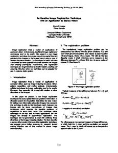
C. Taxonomy of ECC DRAM System Design Space Table I lists a possible design space of ECC schemes for different memory interfaces (e.g. number of channels and DRAM chip widths). We restrict our discussion to memory systems with commodity DDR3 or near future DDR4 DRAM chips and protection schemes with commonly accepted 12.5% ECC storage overhead. 1) x4 DRAM: DRAM chips with a narrow chip interface (x4) provide strong memory protection with high bit efficiency. A x4 ECC DIMM has two ECC DRAM chips so we can implement chipkill-correct with a 64-bit wide channel, which allows a small access granularity (64 bits × burst 8 = 64B). We construct an 8-bit symbol out of 2-burst data from a 4-bit DRAM chip, instead of using a 4-bit symbol, to overcome the codeword length limitation with 4-bit symbols [26]. A 128-bit wide channel with two x4 ECC DIMMs in parallel enables double chipkill-correct. For example, DDDC (double device data correction) or double chip-sparing in Itanium 2 [5] is capable of tolerating up to two x4 DRAM failures using this approach. Even stronger protection of quad chipkill is possible with a 256-bit wide channel. However, these strong protection mechanisms incur a larger access granularity of 128B or 256B for each complete burst operation. 2) x8 and x16 DRAM: High-end servers using DDR and DDR2 memory systems have largely standardized on the use of x4 DRAM devices to obtain the maximum capacity in each rank of memory, with x4 chipkill algorithms and 4 ECC symbols (described in the previous subsection). However, wider DRAM devices (e.g. x8 and x16 DRAMs) have superior pricing and power efficiency than x4 DRAMs [2], [6], [19]. Unfortunately, the wider chip interface demands a wider channel to enable chipkill or double chipkill, compared to x4 DRAMs. With x8 DRAM, chipkill-correct requires a 128bit wide channel, and double chipkill requires a 256-bit wide channel as shown in Table I. x16 DRAM has a much more severe constraint; supporting chipkill demands 256-bit wide channels. Narrow channels with wide DRAM chips (e.g. a 64bit wide channel with x8 or x16, and a 128-bit wide channel with x16) do not have two ECC chips for chipkill correct. Thus, bit error correcting codes have to be used as listed in Table I: an SECDED code for each access in a 64-bit wide channel and a DEC (double bit-bit error correcting) code for each access in a 128-bit wide channel. D. Motivation: System Design Constraints and Trade-offs The different ECC schemes listed in Table I can provide different levels of protection for the memory systems as shown in Figure 1, where normalized MTTF (Mean Time to Failure) is used as the indicator of the protection level. The results are
x8 SECDED chipkill (S-CPK) double chipkill (D-CPK)
x16 SECDED⋆ DEC chipkill (S-CPK)
100 Normalized MTTF
channel count
10 1 0.1
ECC Granularity Chip width
S-CPK D-CPKQ-CPK SEC S-CPK D-CPK SEC
DEC S-CPK
64B 128B 256B 64B 128B 256B 64B 128B 256B x4
x8
x16
Fig. 1. Mean time to failure (MTTF, the higher the better) for design points listed in Table I in the context of a 100 petaflops computing systems (see Section IV for detailed system parameters. SEC refers to SECDED.). The numbers are normalized to the case of 1-channel x4 DRAM data width.
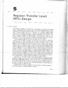
computed by using the system memory failure and reliability models in [24] and [13]. The most important observation is that for the same DRAM chip type (e.g. x4, x8, or x16), ECC schemes with large access granularity at the memory interface can provide stronger memory protection. For example, quadchip kill, requiring 256B data access at the memory interface, has 80X higher MTTF than single chipkill which only requires a 64B data access. Stronger memory protection comes together with a higher overhead. As shown in Table I, strong memory protection requires a wide memory bus, hence, multiple memory channels to work in lock-step. If the access granularity at the processor side, (i.e. the cache line size), does not match the access granularity at the memory subsystem side, significant performance and energy penalties will occur. For instance, chipkill in x8 DRAM uses two memory channels in lockstep mode, increasing the memory access granularity to 128B. If a processor uses 64B cache lines, the memory controller must read twice as much data as the processor requests and then discard half the data after the memory controller computes ECC, wasting power and bandwidth [24]. Similarly, any strong memory protection mechanism with wider DRAM chips (double chipkill for x8, chipkill and double chipkill for x16) necessitates a large access granularity (128B or 256B) and may introduce a granularity mismatch. Unfortunately, matching the granularities at processor side (by using large cache lines) and the memory side cannot guarantee high performance and low energy overhead either, since it adversely impacts performance for applications with low spatial locality. Choosing an optimal access granularity is, in fact, application dependent: an application with low spatial locality favors a smaller access granularity, and one with high spatial locality prefers a larger access granularity. Figure 2 illustrates the instruction per cycle (IPC) variation with data access granularity, assuming matched last-level cache line size and main memory burst data width. For benchmarks such as perlbench and gcc, the IPC drops significantly with increasing
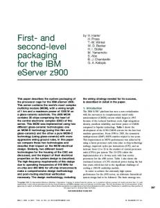
III. MAGE A RCHITECTURE We propose MAGE, a Memory system with Adaptive Granularity and ECC, to provide different combinations of memory access granularity and memory protection techniques (ECC mechanisms). These different combinations are defined as modes in this paper. By selecting an appropriate mode for each application, MAGE can provide high-resiliency, highthroughput, and power-efficient memory systems. Moreover, it can provide an elastic architecture suitable for modern applications with vastly different memory behaviors. MAGE is a hardware-software collaborative solution, consisting of: 1) a smart memory controller that manages data layout, memory scheduling, and memory channel integration (Section III-A); 2) a combination of modified decoupled sector cache [37] and pool-of-subsectors cache [35] that manages data with mixed access granularities in the cache hierarchy (Section III-B); and 3) software support that identifies perpage or per-application access granularity and manages multigranularity physical memory (Section III-C). The modifications to the system stack are minor and can be easily implemented in current mainstream systems. We also briefly review dynamic mode adaption (Section III-D). A. Smart Memory Controller and Main Memory Figure 3 depicts an overview of the proposed MAGE solution applied to a multicore processor, where multi-channel smart memory controllers are shared by all cores and caches via an on-chip network. Each physical memory channel has a standard 72-bit wide bus, with 64-bit data and 8-bit ECC. As shown in Table I, the MAGE architecture supports three memory modes for the memory systems constructed with x4, x8, and x16 DRAM devices. • The fine-grained mode uses each physical memory channel as a 64-bit wide logical channel, enabling 64B memory access. The fine-grained mode uses chipkillcorrect for x4 DRAM systems and SECDED for both x8 and x16 DRAM systems.
64B line 7
64B line 11
Core n-1
72
On-chip Network
MC m-1 72
Common MC logic:
ECC logic
Mode control bit Propagated from Page table Entry (PTE)
Fine-grained mode
ECC logic Medium-grained mode
ECC logic Coarse-grained mode
1
Fine-grained mode
2
64B line 9
MC 1
LLC bank m-1
64B line 8
MC 0
LLC bank i
64B line 5
LLC bank 1
64B line 1
LLC bank 0
64B line 4
access granularity. However, for other benchmarks such as libquantum and soplex, a larger memory access granularity is more favorable and results in higher performance. In summary, an architecture that can give an appropriate access granularity to different applications will fully exploit the application’s locality characteristics and improve the overall system performance. Moreover, the architecture will naturally provide stronger memory protection to the applications that prefer higher granularity as shown in Table I.
Core 2
64B line 0
Fig. 2. Instructions per cycle (IPC, higher is better) variation with access granularity (i.e. the last-level cache line size and matched main memory access data width). The simulation parameters are the same as shown in Table III in Section IV.
Core 1
Core 0
Comodity DIMMs
512B
Comodity DIMMs
128B 256B Cache Line Size
1 2
MC PHY
3
Medium-grained mode
72
Comodity DIMMs
64B
72
64B line 10
450.soplex
64B line 3
462.libquantum
1
64B line 6
403.gcc
3 2
64B line 2
400.perlbench
Cache Line Tag selection bits Valid bit vector 64B cache lines in a set
Tag
Comodity DIMMs
0.8 0.7 0.6 0.5 0.4 0.3 0.2
All tags
IPC
4
3 Coarse-grained mode
MAGE architecture overview. Note that last-level caches (LLCs) can be shared or private, and MCs (memory controllers) can be attached through either LLCs or directly through the NoC. Fig. 3.
•
•
The medium-grained mode ties two physical memory channels in lock-step to construct a 128-bit wide logic channel. This wide memory channel increases memory access granularity to 128B but provides stronger memory protection (double chipkill for x4 DRAMs, chipkill for x8 DRAMs, and DEC for x16 DRAMs) than the fine-grained mode. The coarse-grained mode uses four physical memory channels as a 256-bit wide logical channel, enabling 256B memory access, while providing even stronger memory protection (quad chipkill for x4 DRAMs, double chipkill for x8 DRAMs, and chipkill for x16 DRAMs) than the medium-grained mode.
Although MAGE also can support other modes with even larger granularity and stronger memory protection, we only show these three modes because of the diminishing return (or possible degradation) of the performance and power efficiency with larger granularities. The key idea of MAGE is to use the optimum access granularity and ECC scheme for each memory access. Allowing mode adaptation for each memory access, however, incurs a large storage overhead for managing per-block mode information. Application-level adaptation may ease this burden, but the adaptation is too coarse-grained; often, different memory segments or objects within an application favor different access granularities. The best place to apply MAGE’s mode adaptation is in the virtual memory manager, which manages memory pages and segments and translates memory addresses. In this study, we assume that the virtual memory manager manages the mode information for each physical memory page and propagates this information through the memory hierarchy to the memory controller. For MAGE memory controllers, there are three considerations: ECC and memory channel management, data layout, and memory scheduling.
5
1) ECC and Memory Channel Management: Each smart multi-channel memory controller has ECC logic for different levels of memory protection: SECDED, chipkill, double chipkill, and quad chipkill. As shown in Table I, strong memory protection and its associated large granularity require the memory controller to access multiple memory channels in lock-step, but less strong memory protection and its associated small granularity only need to access a single memory channel. Hence, a smart memory controller in the MAGE architecture can have multiple physical memory channels and control the physical channels independently or simultaneously based on the mode granularity. Figure 3 describes such a memory controller. 2) Data Layout: Since MAGE provides different ECC protections for memory regions with different localities and access granularity preferences, the ECC codes and the data layout need to be adjusted accordingly. It is important to maintain compatible data layouts to reduce dynamic mode switching overhead (we discuss dynamic mode adaption in Section III-D). For example, MAGE with three modes as mentioned above (64B fine-grained mode, 128B mediumgrained mode, and 256B coarse-grained mode) first interleaves data at a 256B boundary among all memory controllers, then interleaves 64B data blocks across all four 64-bit physical channels within the same memory controller as shown in Figure 3. This layout ensures that the data layout does not change in different modes, and dynamic mode switching only incurs ECC reconstruction overhead. 3) Scheduling Policy: In the MAGE architecture, the memory controller may receive requests with different access granularities. This poses a significant challenge in memory scheduling. For instance, even a modern PAR-BS [30] scheduling policy emphasizing fairness may still unfairly defer a coarse-grained request within a batch, which needs to access multiple physical channels, when the memory controller has many pending fine-grained requests that access only one physical channel (and hence are easier to schedule than coarsegrained requests). This unfair service with mixed granularity scheduling is similar to the problem described in AGMS [40]. To avoid unfair scheduling, we prioritize medium-grained and coarse-grained requests when they are delayed due to pending fine-grained requests, as in AGMS [40]. B. Cache Hierarchy MAGE with multi-granularity memory access necessitates a multi-granularity cache hierarchy. Although sector caches [27] can provide this functionality, they cause significantly more cache misses than non-sectored caches. On the other hand, a conventional non-sectored cache can manage multi-granularity data with minimal modification. By default, the cache uses 64B cache lines. When the cache receives a 128B or wider data, it allocates two or more 64B cache lines in the same set of the set-associative cache to store the data and lets the cache lines share the same tag entry. To enable multiple 64B cache lines to share the same tag entry with minimal timing overhead, we leverage the combination of decoupled sector cache [37] and pool-of-subsectors cache [35] and add a bit vector to denote cache lines that share a tag in the same set. A
cache line can easily find its associated tag by the tag selection bits, and all 64B cache lines pointed to by the bit vector are considered as a logical sub-cache line within a larger cache line. This design enables a more elastic mapping between the sectors and tags than either decoupled sector cache or poolof-sectors cache, reducing the miss rate to about the same as that of non-sector caches. The internal bus width in the cache is provisioned based on the smallest granularity (64B) and remains the same for different granularities with different modes. By supporting the critical sector first (i.e. bringing the requested 64B sector first to the cache before fetching the rest of the sectors), and utilizing a pipelined non-blocking cache architecture, the performance degradation caused by fetching the larger cache line can be negligible. The MAGE cache hierarchy does not require changes to the cache coherency protocol, because large cache lines actually consist of smaller independent cache lines (64Byte) and the coherency protocol still applies to the 64B cache lines. C. Software Support In the MAGE architecture, the virtual memory manager is responsible for managing memory pages with different granularities and ECC schemes. We use the virtual memory interface to enable software to specify the preferred mode for each page; a page table entry (PTE) is augmented to incorporate the per-page mode information, which is propagated through the TLB, the cache hierarchy, and the memory controllers. This mechanism of adding a per-page trait is similar to AGMS [40] and Page Attribute Tables (PAT) in the x86 architecture [18]. When the same physical page is mapped to multiple virtual memory pages, all virtual pages need to have the same mode as the first virtual page mapped to the physical memory page. The OS can ensure this when allocating pages and page table entries. Reverse page tables in Linux kernel 2.6 and later can be used to expedite the process. The adaptation of access modes can be done either statically at compile time or dynamically by the OS with the assistance of hardware. In the static approach, the programmer or a compiler provides granularity information when allocating memory objects. For instance, we can define a new array attribute in Fortran or add a new parameter to malloc/new in C/C++. The system or compiler will use strong memory protection ECCs for large access granularities and less strong but more efficient memory protection ECCs for smaller access granularities if the programmer does not choose the ECCs. Although it is natural to assign appropriate modes according to data structure type and the associated access patterns, a programmer can also denote access modes from the memory protection perspective by assigning strong memory protection modes (associated with large access granularity) to critical data or regions (such as OS or mission critical applications) and less strong but more efficient memory protection modes (associated with small access granularity) to temporary data that can be easily reconstructed from the critical data, regardless of the data structure type and the memory access pattern. D. Discussions on Dynamic Adaptive Switching MAGE can also dynamically change memory access granularity and ECC when beneficial. To do this, the OS or run-time
6
IV. E VALUATION M ETHODOLOGY Table I shows that the design space of MAGE can be very large given the different configurations of DRAM devices, memory channels, and cache line sizes. While future memory systems prefer wider DRAM chips because of both cost and energy benefits [19]; memory systems with x16 DRAM chips incur much more storage overhead than systems with x4 and x8 DRAM chips, which makes x16 chips less cost-effective when building large scale systems with strong resiliency requirements. Therefore, in our evaluations of MAGE, we focus on x8 DRAM based memory systems because of their more balanced benefits and overheads. Table II illustrates the three modes we choose for the MAGE architecture in this study, where FG-S denotes fine-grained mode combining 64B granularity with SECDED, MG-C denotes medium-grained mode combining 128B granularity with chipkill, and CG-D denotes coarse-grained mode combining 256B with doublechipkill, respectively. TABLE II BASELINE MEMORY SYSTEM CONFIGURATIONS EVALUATED IN OUR EXPERIMENTS . FG-S, MG-C, CG-D DENOTE FINE - GRAINED MODE , MEDIUM - GRAINED MODE , AND COARSE - GRAINED MODE , RESPECTIVELY. mode FG-S MG-C CG-D
# of channels 1 2 4
cache line 64 byte 128 byte 256 byte
× 8 DRAM ECC SECDED Single ChipKill Double ChipKill
A. System Architecture and Modeling Results MAGE can be used in all systems from individual work stations through petaFLOPS systems and for future exascale systems to provide enhanced performance, resiliency, and power efficiency. In this paper, we study the benefits and impacts of MAGE under the context of near future 100 petaFLOPS supercomputing systems. Figure 4 shows the block diagram of a 100 petaFLOPS system, consisting of O(100K) to O(1M) manycore-processor based nodes connected using fast system interconnects. As shown in Figure 4, we assume each MAGE-enhanced manycore processor consists of multiple clusters connected by a 2D-mesh on-chip network. A cluster has one or more (4 in our study) multithreaded Niagaralike [21] cores (each augmented with a 4-way SIMD unit) and a multi-banked L2 cache. Each core has 4 active threads and 32KB 4-way set-associative L1 I/D caches. All L1D caches use a fixed 64B cache line size because most modern applications will benefit from this L1 cache line size [39].
Memory
Core Cluster
Memory
MC
MC
MC
MC
Memory
Memory
Network
Memory
Memory
MC
MC
Memory
Memory
MC
MC
MC
MC
Memory
Memory
Other sockets/nodes
Router Hub Many-core Chip
Fig. 4.
MC
MC
Memory
Memory
Core Cluster
Core ... Core Core Crossbar L2 L2 L2 ... Bank Bank Bank
module should collect spatial locality information, memory failure rates, memory channel and cache usage, etc. We assume that hardware performance counters can collect these statistics during program execution, and the OS can periodically evaluate and execute dynamic mode switching. Since changing the granularity and ECC requires ECC reconstruction, which incurs streaming memory reads and writes of a memory page, the OS must take into account the cost of this granularity switching. Also, dynamic adaption is only beneficial for applications whose memory pages change access patterns and thus access granularity preferences during execution. We use a static per-memory-page based mode selection in this study and leave exploration of dynamic adaption to future work.
Conceptual view of the target system architecture. TABLE III
PARAMETERS OF
THE TARGET SYSTEM FOR EVALUATION .
Core Technology (nm) L1 Cache L2 Cache Clock rate (GHz) Peak Perf. w. SIMD (GFLOPs) Additional ECC logic Area (mm2 ) Max Dyn power (W) MAGE processor Core count Total threads Peak Perf. w. SIMD (GFLOPs) Memory Controllers (MCs) Memory type Processor Area (mm2 ) Processor TDP Power (W) 100 petaFLOPS system Node count Memory BW/Node (GB/S) Memory Capacity/node (GB) Network BW/Node (GB/S) Memory DIMMs Energy including I/O (pJ/bit)
16 32KB, 16way, 64B block 1MB, MAGE with 3 modes 2.5 10 Double Chipkill 0.0079 0.0096 64 256 640 4 quad-channel MCs DDR4-2133 177.6 87.7 156250 273 32 60 DRAM / PCRAM 35 / 41
As shown in Figure 4, all cores in a cluster share a multibanked L2 cache, with 1MB per bank and the number of L2 banks equal to the number of cores per cluster. The L2 caches are set associative, being 16-way, 8-way, and 4-way for FG-S mode, MG-C mode, and CG-D mode, respectively. A crossbar is used to connect cores and L2 cache banks for intracluster communications. A two-level hierarchical directorybased MESI protocol is used for cache coherency at both L1 and L2 cache levels. Table III lists the detailed system parameters of the MAGE enhanced manycore processor nodes and the 100 petaFLOPS system as projected in supercomputing studies [7], [33]. The 100 petaFLOPS system is projected to be available around the year 2015 to 2017, when 16nm technology will be ready for commercial production. We use a modified McPAT [22] to estimate the power, area, and clock rate of the MAGE
7
TABLE IV B ENCHMARK CHARACTERISTICS : L AST- LEVEL CACHE MPKI AND PAGE ACCESS GRANULARITY PREFERENCE DISTRIBUTION .
hmmer leslie3d sphinx3
Benchmark
MPKI
400.perlbench 401.bzip2 403.gcc 429.mcf 445.gobmk 456.hmmer 458.sjeng 462.libquantum 464.h264ref 483.xalancbmk
1.15 6.15 0.86 52.6 1.39 2.74 0.82 24.88 1.67 5.6
libquantum Soplex
Pages Accessed in 64B, 128B, and 256B 10.5% 24.2% 65.3% 41.3% 29.6% 29.1% 8.9% 4.0% 87.1% 3.9% 7.8% 88.4% 24.4% 37.4% 38.2% 0.6% 6.1% 93.3% 98.5% 0.3% 1.3% 24.4% 15.1% 60.5% 32.1% 43.7% 24.2% 21.8% 12.7% 65.5% perlbench gobmk xalancbmk
milc lbm
Benchmark
MPKI
410.bwaves 433.milc 436.cactusADM 437.leslie3d 447.dealII 450.soplex 459.GemsFDTD 470.lbm 481.wrf 482.sphinx3
13.37 19.93 4.69 8.71 1.27 27.76 18.44 27.11 5.14 16.42
bzip2 sjeng cactusADM
Pages Accessed in 64B, 128B, and 256B 16.7% 4.7% 78.6% 44.1% 6.0% 49.9% 10.3% 0.5% 89.1% 1.9% 1.3% 96.8% 0.0% 19.5% 80.4% 34.7% 26.3% 39.0% 4.7% 12.2% 83.1% 0.1% 99.8% 0.1% 4.4% 28.4% 67.2% 1.9% 30.1% 68.0%
gcc h264ref dealII
mcf
0.9
0.9
bwaves
GemsFDTD
wrf
0.7
0.8 0.5
0.5
IPC
0.7
IPC
IPC
0.7
0.6
0.3
0.5 0.3
0.4 0.1
0.3
0.1 64B
128B 256B Access granularity
512B
(a) Application group of increasing IPC.
64B
128B 256B Access granularity
512B
(b) Application group of decreasing IPC.
64B
128B 256B Access granularity
512B
(c) Application group of non-monotonic IPC.
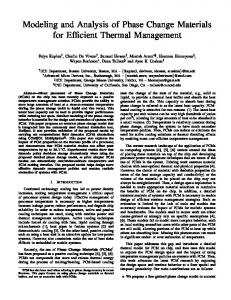
IPC values (higher is better) of SPEC CPU2006 benchmarks with different access granularities. Based on the different behaviors of the IPC curves, the applications are categorized into three groups. Fig. 5.
enhanced manycore architecture. As the modeling results in Table III indicate, a 64-core MAGE processor, with a 176 mm2 die size, can provide an aggregate throughput of 640 GFLOPS. Thus, a 100 petaFLOPS system will require 156250 nodes. According to [7], [33], each processor node needs ∼250 GB/s of memory bandwidth. Based on the JEDEC roadmap [20] and the clock rate of the cores, DDR4-2133 equivalent memory can be used to satisfy the requirement. Thus, each MAGE manycore processor node needs 16 memory channels containing a single rank DDR4-2133 DIMM. The 16 memory channels are connected to four memory controllers with four channels each, where all channels of a memory controller can work independently or in lock-step according to the requirement of different modes as shown in Table II. The overhead of a MAGE memory controller is quite small, as it only needs a 2-4 decoder to decode the mode information in memory requests and two extra sets of ECC logic (an encoder, a decoder, and a corrector). Its impact on processor power and latency is negligible because the 2-4 decoder latency and timing are insignificant compared to a memory access, and only one set of ECC logic is activated for each access. Since each baseline architecture also has and utilizes one set of ECC logic, the power consumption of MAGE memory controller is similar to the baseline architectures. The extra sets of ECC logic only affects the area of the memory controller. Based on the ECC logic implementation in [9], we modified McPAT to compute the area and dynamic power of the delay-optimized RS ECC logic at 16nm. As shown in Table III, the double chipkill (in CG-D) ECC logic has area of 0.0079 mm2 and max dynamic power of 9.6mW. Both area and power of the ECC logic is negligible compared to the total processor area and power, which further confirms the low overhead of MAGE memory controllers. The memory
controller is modeled to support the PAR-BS [30] scheduling policy. In large scale systems, checkpointing is another standard way to improve system resiliency by recovering the system state in the event of an uncorrectable error. We model an advanced two-level checkpointing scheme and store checkpoints both locally within a node and globally in neighboring nodes [13]. Both local and global checkpoints are assumed to be stored in emerging non-volatile PCRAM DIMMs connected to memory controllers as in [13] since hard disk drives (HDD) have been shown to be too slow for systems at the 100 petaFLOPS scale and beyond [13]. We run CACTI [23] and NVSim [12] to compute the energy per access of the main memory DRAM DIMMs and checkpointing PCRAM DIMMs and list the modeling results in Table III. The architecture parameters and modeling results listed in Table III are used in our evaluations. B. Simulation Setup and Workload Profiling We evaluate MAGE using a combination of application characteristic profiling and cycle-level simulations. For the cycle-accurate simulations, we use McSim [1], a Pin [28] based manycore simulation infrastructure. McSim models multithreaded in-order cores, caches, directories, on-chip networks, and memory channels in detail. We modified McSim to support the changes in caches and memory controllers. We find the representative simulation phases of each application and their weights using Simpoint 3.0 [38]. Each hardware thread runs a simulation phase and the number of instances per phase is proportional to its weight. We skip the initialization phases of each workload and simulate 2 billion instructions unless it finishes earlier. Before evaluating our MAGE architecture, we profile the performance and memory access behavior of all applications
8
and use the profiling results to guide workload construction, cycle-accurate simulations, and overall system evaluations. We select 20 applications from both CINT (integer benchmarks) and CFP (floating point benchmarks) of the SPEC CPU2006 benchmark suite [29], with 10 benchmarks from each category. We use PIN [28] to collect profiling information, and emulate a system with a 1MB last level cache. For each application, we obtain access granularity preferences of all data memory pages touched during the execution of the application and misses per kilo instructions (MPKI) at the LLC as the indicator of the memory bandwidth demand. To obtain the access granularity preference of each memory page, we profile which 64B data cache lines are referenced within each memory page. We then aggregate the per-cache line access count across each 4kB page boundary to determine the preferred access granularity of the page. The per-page access preference is then fed into McSim to determine the appropriate mode of each page during the cycleaccurate simulations. In practical systems, this information can be provided by the OS or marked at compile time as mentioned in Section III. Since the focus of this work is architecture design, we do not discuss the OS or compiler implementation. Instead, we use the profiling results to guide our simulations. The distributions of access granularity preferences of memory pages are also used in evaluating the system memory MTTF in Section V, where the MAGE architecture applies different levels of memory protection to different memory regions, based on the access granularity preference distribution. Table IV summarizes our profiling results on MPKI at the LLC and the distribution of page access granularity preference. The three applications with the highest MPKI are mcf, soplex, and lbm. Other applications, such as gcc and sjeng, are less memory intensive and tend to have quite low MPKI. Some of the applications, such as hmmer, always access the memory in large granularity. In contrast, the memory accesses of sjeng are mostly in small granularity. Since an application may not evenly access all memory pages, the overall access granularity preference at the application level may not be the same as that at the average of the individual memory pages. Thus, when mixing applications according to their overall access granularity preferences, the access granularity preference of each memory page is not sufficient. Hence, we also run simulations for each SPECCPU2006 benchmark to find instruction per cycles (IPCs) with different access granularities, as an indicator of the preferred memory access granularity at the application level. The architecture configurations used in these simulations are the same as in Section IV-A, assuming static baseline architectures with no mode adaption. Figure 5 illustrates the simulation results of individual applications with different memory access granularities. We categorize all the applications into three types, as shown in Figure 5. Figure 5(a) shows 7 applications with an increasing IPC as the access granularity increases. Figure 5(b) shows 9 applications with lower IPC at larger access granularities. Some applications demonstrate non-monotonic IPC variations in the considered range of memory access granularity, for which we can observe that each IPC curve has a sweet spot at a medium cache line size as illustrated in Figure 5(c).
Mixed workloads used in the experiments. The column of “Applicaton% with large granularity” represents the percentage of applications that prefer memory accesses with a large granularity (>64B). For example, each workload in G-2 includes 2 applications that prefer the large memory access granularity (>64B). Fig. 6.
Based on the single application profiling and simulation results, we construct 11 mixed workloads with different memory bandwidth demands and access granularity preferences. As listed in Figure 6, each shadowed square represents a selected application in a specific workload. The mixed workloads can be further divided into 5 groups (G-1 to G-5). The portion of applications that favor the large memory access granularity increases among the groups from 0% (G-1) to 100% (G-5). Within each group, the workloads are sorted in the order of increased memory bandwidth demand. For example, in group G-2, WL-02 and WL-04 have the lowest and highest average memory bandwidth demand, respectively. V. R ESULTS We first present and analyze the performance and power efficiency of MAGE as a single manycore processor node, and then study the system implications of MAGE architecture on resiliency, performance, and power efficiency in the context of a near-future 100 petaFLOPS system. A. Performance and Power Advantages of MAGE Figure 7 shows the power, instructions per cycle (IPC), and system energy-delay product (EDP) of the baseline architecture and the MAGE architecture running all 11 mixed workloads. In order to match the three modes supported by the MAGE architecture as shown in Table II and III, the baseline architecture is assumed to run all applications in a single fixed mode: FG-S, MG-C, or CG-D, while the MAGE architecture accesses different memory pages of the applications using adaptive modes. Figure 7(a) shows the IPC and the dynamic power breakdown of the architectures. As mentioned in Section IV-B, the memory bandwidth demands of the constructed workloads increase both across workload groups (from G-1 to G-5) and within the same group (e.g. from WL-02 to WL-05). Thus, as moving from WL-01 to WL-11, the workloads are increasingly memory-bound and limited by the memory bandwidth, which causes the general decreasing trend in overall IPCs. As shown in Figure 7(a), the advantages of MAGE are demonstrated by its superior performance and power consumption. MAGE always achieves the best IPC and power consumption, compared to all baseline configurations across all workloads. For workloads composed of applications with
50
50 L2 Dynamic
(NoC + MC) Dynamic
IPC
40
WL-01
WL-02
G-1
WL-03
WL-04
WL-05
WL-06
G-2
WL-07
WL-08
WL-09
G-3
WL-10
G-4
FG-S MG-C CG-D MAGE
FG-S MG-C CG-D MAGE
FG-S MG-C CG-D MAGE
FG-S MG-C CG-D MAGE
FG-S MG-C CG-D MAGE
FG-S MG-C CG-D MAGE
FG-S MG-C CG-D MAGE
0
FG-S MG-C CG-D MAGE
10
0
FG-S MG-C CG-D MAGE
20
10
FG-S MG-C CG-D MAGE
30
20
FG-S MG-C CG-D MAGE
30
IPC
Core Dynamic
40
FG-S MG-C CG-D MAGE
Processor Dyanmic Power (W)
9
WL-11 G-5
Average
Processor Dynamic
Processor Leakage
Mem Dynamic
Mem Leakage
2.5 2 1.5 1 0.5 0
Normalized EDP
60 40 20
WL-01 G-1
WL-02
WL-03 G-2
WL-04
WL-05
WL-06 G-3
WL-07
WL-08
WL-09 G-4
WL-10
FG-S MG-C CG-D MAGE
FG-S MG-C CG-D MAGE
FG-S MG-C CG-D MAGE
FG-S MG-C CG-D MAGE
FG-S MG-C CG-D MAGE
FG-S MG-C CG-D MAGE
FG-S MG-C CG-D MAGE
FG-S MG-C CG-D MAGE
FG-S MG-C CG-D MAGE
FG-S MG-C CG-D MAGE
FG-S MG-C CG-D MAGE
0
WL-11 G-5
Average
(b) System power and normalized EDP (normalized against FG-S for each workload) Fig. 7. Power (lower is better), IPC (higher is better), and normalized EDP (lower is better) of the baseline and MAGE-enhanced manycore
systems running the mixed workloads from WL-01 to WL-11, with all workloads being categorized into 5 groups from G-1 to G-5 as described in Section IV-B. ‘FG-S’, ‘MG-C’, ‘CG-D’, and ‘MAGE’ denote baseline systems running in each mode and the MAGE system with mode adaption, respectively.
different access granularity preferences (WL-02 to WL-09), MAGE demonstrated 3.5% to 26.4% improvements in performance (15.6% on average) and 1.2% to 8.9% improvements in dynamic processor power consumption (6.7% on average), compared to the best baseline architecture. Even for the workloads composed of applications with uniform access granularity preferences, MAGE still achieves better performance and power consumption than all the baseline architectures. This is because even if an application demonstrated no overall diverged granularity preference at the application level, there are still memory pages that prefer different granularities within the same application. The per-page mode adaptation feature supported by MAGE can fully exploit the different preferences, thus further improving the performance and power efficiency. By assigning appropriate modes to memory pages of the mixed applications, MAGE significantly reduces L2 cache misses, which leads to better performance and power efficiency. The baseline architectures have higher L2 miss rates than the MAGE architecture because of the mismatch between the architecture access granularity and the preferred access granularity of applications’ memory pages, which causes more traffic not only to the NoC and the main memory system but also to L1 caches since each L2 miss and replacement can cause multiple inclusive L1 cache lines to be invalidated and fetched again. The extra traffic to L1 caches, L2 caches, directories, NoC, and memory controllers leads to the degraded performance and power efficiency of the baseline architectures, compared to the MAGE architecture as shown in Figure 7(a). Figure 7(b) shows the normalized EDP and total system power with both dynamic and leakage power of the manycore processor and main memory modules. The higher L2 cache miss rates of the baseline architectures also lead to
higher main memory dynamic power consumption, compared to the MAGE architecture. MAGE further demonstrates its advantage through its best system EDP for all workloads with improvements ranging from 4.5% to 41%, compared to the best baseline configuration. B. From Single Node to Large-scale System In this section we evaluate reliability, performance, and power efficiency of baseline architectures with fixed modes and MAGE in the context of near-future 100 petaFLOPS systems as mentioned in Section IV. Figure 8 shows the normalized mean time to failure (MTTF) of all architecture at the overall 100 petaFLOPS system level. The MTTF values are computed using the failure and reliability models in [24], [25], [36], and the access granularity preferences of all memory pages as shown in Table IV. MAGE’s MTTF is higher than FG-S and MG-C, but 5X lower than CG-D. This is because MAGE does not provide all memory pages with the highest protection level of double-chipkill as CG-D does. However, CG-D provides the highest reliability at the cost of the highest penalties on performance and power efficiency of all configurations as shown in Figure 7. If the CG-D configuration is out of consideration because of its prohibitively high overhead on performance and power, MAGE outperforms both FG-S and MG-C configurations in all aspects, including performance, power efficiency, and reliability. Although MAGE has lower MTTF than CG-D, this drawback can be compensated by checkpointing that is standard in all large-scale computing systems for system resiliency. A checkpointing scheme provides both MAGE and the baseline configurations with the same system reliability, but at different performance and energy overheads. Figure 9 shows a complete view of overall timing, energy, and EDP, including both native
Normalized EDP
80
FG-S MG-C CG-D MAGE
System Power (W)
(a) Processor dynamic power and IPC
Normalized MTTF
100 10 1 0.1 FG-S
MG-C
CG-D
MAGE
Fig. 8. MTTF (higher is better) for computing systems with baseline
Normalized to FG-S Execu!on
10 1.4 1.2 1 0.8 0.6 0.4 0.2 0
architecture and MAGE at 100 petaFLOPS scale.
error free execution and checkpointing operations, for the target 100 petaFLOPS system. The native execution results of performance and power are averaged over all workloads’ simulation results as shown in Figure 7. The checkpointing overhead is calculated with the checkpointing optimization and evaluation modeling tools in [13], [24] under the same assumption of hybrid checkpointing strategy as in [13], [24] and Section IV-A. As seen in Figure 9, regardless whether accounting for checkpointing overhead or not, MAGE achieves the best performance (total execution time), energy consumption, and energy-delay-product (EDP). This is due to the synergy of: 1) performance and energy improvements for the error free execution on MAGE; 2) the balance of errorfree execution and system checkpointing overhead on MAGE. Overall, MAGE outperforms the FG-S, MG-C, and CG-D baseline configurations by 24%, 26%, and 28% respectively on overall system EDP. The native execution time and energy of MAGE are much less than those of the three baseline configurations. Although CG-D’s checkpointing overhead is noticeably lower than that of MAGE and other configurations because of its relatively high MTTF as shown in Figure 8, its high native execution time and energy consumption result in the highest EDP consumption among all configurations. In summary, MAGE achieves both the best performance and energy efficiency in the context of the entire large-scale system with checkpointing. C. Supporting Graceful System Burn-in and Aging Another benefit of MAGE is its ability to tune the ECCgranularity modes with DRAM memory aging. The DRAM hard error rate follows the Weibull Distribution [25] and has high error rate both at the beginning and the end of lifetime. MAGE is able to adjust the appropriate ECC schemes for different error rates and distributions at any stage of the DRAM life cycle to retain high overall reliability, performance, and energy efficiency. For example, at both the beginning and the end of DRAM life cycle when hard error rates are high, MAGE can adaptively tune up the protection level with the stronger ECC to achieve higher reliability; for mid-aged memories with a relatively low error rate, MAGE can achieve better performance and energy efficiency by adaptively tuning down the memory protection level. On the contrary, architectures without mode adaption either suffer from low performance and energy efficiency at the mid-aged phase because of the overdesigned memory protection, or suffer from frequent system failures because of insufficient memory protection at the burnin and age-out phases. VI. R ELATED W ORK There have been studies of many kinds of ECCs, which provide the memory systems with different levels of relia-
Execu on
FG-S MG-CCG-DMAGE Timing
Checkpoi ng
FG-S MG-CCG-DMAGE Energy
FG-S MG-CCG-DMAGE EDP
The complete view of overall system timing, energy, and EDP (lower is better) of MAGE and baseline architectures with static modes for hundred petaFLOPS supercomputing systems. The values include both checkpointing overhead and native execution, and are normalized against native execution of FG-S. Fig. 9.
bility. SECDED [14], [16] is the industrial standard ECC, but can only correct single-bit errors. Chipkill ECCs have been implemented by multiple industry vendors in various forms to address DRAM chip failures, including interleaved ECC by IBM [11], symbol-based ECC by AMD [34] and advanced ECC by HP [3]. However, the power and performance overhead of chipkill ECC schemes is high, because they all require two or more DIMMs to work in lock-step. To overcome this problem, Li et al. [24] proposed memory protection using a BCH (Bose-Chaudhuri-Hocquenghem) [8], [15] code to maintain high reliability, while reducing performance and power overhead in comparison to chipkill ECCs. Yoon et al. proposed dynamic/adaptive granularity memory systems (AGMS [40] and DGMS [41]) that selectively use fine-grained 8-byte access and coarse-grained 64-byte access for applications with different locality. However, neither AGMS nor DGMS considered granularities larger than 64 bytes. Based on a prior study [39], many applications can benefit significantly from a larger access granularity than 64-byte access. Moreover, AGMS and DGMS only work with memory systems with single bit-error protection, which is insufficient for systems for 64 petaFLOPS and beyond [7], [24]. Previous work looked at either ECC or access granularity in isolation for memory systems, but not both at the same time. To the best of our knowledge, this work is the first attempt to study the interaction of ECC and memory access granularity. It is also the first to propose combining access granularity and ECC into modes and taking advantage of flexible mode switching to achieve high system performance, power efficiency, and resiliency. VII. C ONCLUSIONS With this work, we have identified the key relationships between ECC and memory access granularity. We proposed MAGE, a Memory system with Adaptive Granularity and ECC, to achieve high performance, power efficiency, and resiliency for large-scale computing systems. MAGE enables adaptive selection of appropriate modes that combine different access granularities and ECC schemes for applications with different memory behaviors. MAGE concurrently satisfies three key requirements: improved performance, power-efficiency, and resiliency for future large-scale computing systems. Our simulation results show that MAGE achieves more than a 28% improvement in energydelay product compared to the best existing systems with static granularity and ECC.
11
R EFERENCES [1] “McSim: A Manycore Simulation Infrastructure,” http://scale.snu.ac.kr/mcsim. [2] “Micron system power calculator,” http://www.micron.com/support /designsupport/tools/powercalc/powercalc.aspx. [3] D. G. Abdoo and D. Cabello, “Error correction system for N bits using error correcting code designed for fewer than N bits,” U.S. Patent 5,490,155, Feb. 1996. [4] AMD, “BIOS and Kernel Developer’s Guide for AMD NPT Family 0Fh Processors, Technical Report,” Nov. 2009. R R [5] R. Angy, E. DeLano, and M. Kumar, “The Intel Itanium
Processor 9300 Series: A Technical Overview for IT Decision-Makers,” http://download.intel.com/pressroom/archive/reference/Tukwila Whitepaper.pdf. [6] S. Ankireddi and T. Chen, “Challenges in thermal management of memory modules,” http://electronics-cooling.com/html/2008 feb a3.php. [7] K. Bergman, et al., “ExaScale Computing Study: Technology Challenges in Achieving Exascale Systems.” 2008, DARPA IPTO sponsored report. [8] R. C. Bose and D. K. Ray-Chaudhuri, “On a class of error correcting binary group codes,” Information and Control, vol. 3, pp. 68–79, 1960. [9] B. Chen, “Hardware implementation of error control decoders,” Computer Engineering, Case Western Reserve University,” Technical Report (Master Thesis), 2008. [10] C. L. Chen and M. Y. Hsiao, “Error-correcting codes for semiconductor memory applications: A state-of-the-art review,” IBM J. Research and Development, vol. 28, no. 2, pp. 124–134, Mar. 1984. [11] T. Dell, “A White Paper On The Benefits Of Chipkill-Correct ECC for PC Server Main Memory,” IBM Microelectronics Division,” Technical Report, Nov. 1997. [12] X. Dong, N. P. Jouppi, and Y. Xie, “PCRAMsim: System-Level Performance, Energy, and Area Modeling for Phase-Change RAM,” in Proceedings of the 2009 International Conference on Computer-Aided Design, 2009. [13] X. Dong, N. Muralimanohar, N. Jouppi, R. Kaufmann, and Y. Xie, “Leveraging 3D PCRAM Technologies to Reduce Checkpoint Overhead for Future Exascale Systems,” in Proceedings of the Conference on High Performance Computing Networking, Storage and Analysis, 2009. [14] R. W. Hamming, “Error correcting and error detecting codes,” Bell System Technical J., vol. 29, pp. 147–160, Apr. 1950. [15] A. Hocquenghem, “Codes correcteurs d’erreurs,” Chiffres (Paris), vol. 2, pp. 147–156, 1959. [16] M. Y. Hsiao, “A class of optimal minimum odd-weight-column SECDED codes,” IBM J. Research and Development, vol. 14, pp. 395–301, 1970. [17] A. Hwang, I. Stefanovici, and B. Schroeder, “Cosmic rays don’t strike twice: Understanding the characteristics of DRAM errors and the implications for system design,” in Proc. the 17th Int’l Conf. Architectural Support for Programming Languages and Operating Systems (ASPLOS), Mar. 2012. R [18] Intel IA-64 and IA-32 Architecture Software Developer’s Manual, Intel Corp., Mar. 2010. [19] B. Jacob, S. Ng, and D. Wang, Memory Systems: Cache, DRAM, Disk. San Francisco, CA, USA: Morgan Kaufmann Publishers Inc., 2007. [20] JEDEC, “http://www.jedec.org/.” [21] P. Kongetira, K. Aingaran, and K. Olukotun, “Niagara: A 32-Way Multithreaded Sparc Processor,” IEEE Micro, vol. 25, no. 2, 2005. [22] S. Li, et al., “McPAT: An Integrated Power, Area, and Timing Modeling Framework for Multicore and Manycore Architectures,” in Proceedings of the 42nd Annual IEEE/ACM International Symposium on Microarchitecture, 2009. [23] S. Li, K. Chen, J. Ahn, J. B. Brockman, and N. P. Jouppi, “CACTIP: Architecture-Level Modeling for SRAM-based Structures with Advanced Leakage Reduction Techniques,” in ICCAD, 2011. [24] S. Li, et al., “System Implications of Memory Reliability in Exascale Computing,” in Proc. the Conf. High Performance Computing, Networking, Storage and Analysis (SC), 2011. [25] X. Li, M. C. Huang, and K. Shen, “A Realistic Evaluation of Memory Hardware Errors and Software System Susceptibility,” in Proceedings of the 2010 USENIX conference on USENIX annual technical conference, ser. USENIXATC’10, 2010, pp. 6–6. [26] S. Lin and D. J. Costello Jr., Error Control Coding: Fundamentals and Applications. Prentice-Hall, Inc., Englewood Cliffs, NJ, 1983. [27] J. S. Liptay, “Structural aspects of the system/360 model 85, part II: The cache,” IBM Systems Journal, vol. 7, pp. 15–21, 1968. [28] C.-K. Luk, et al., “Pin: Building Customized Program Analysis Tools with Dynamic Instrumentation,” in PLDI, Jun 2005.
[29] H. McGhan, “SPEC CPU2006 Benchmark Suite,” in Microprocessor Report, Oct 2006. [30] O. Mutlu and T. Moscibroda, “Parallelism-aware batch scheduling: Enhancing both performance and fairness of shared dram systems,” in Proc. the 35th Int’l Symp. Computer Architecture (ISCA), June 2008. [31] J. A. Nerl, K. Pomaranski, G. Gostin, A. Walton, and D. Soper, “System and method for controlling application of an error correction code,” US Patent, US 7,437,651, Oct. 2004. [32] ——, “System and method for applying error correction code (ECC) erasure mode and clearing recorded information from a page deallocation page,” US Patent, US 7,313,749, Dec. 2007. [33] R. Stevens and A. White, “A DOE laboratory plan for providing exascale applications and technologies for critical DOE mission needs,” in SciDAC Workshop, June 2010. [Online]. Available: {http://computing.ornl.gov/workshops/scidac2010/ presentations/r stevens.pdf,July2010.SciDACWorkshop} [34] I. S. Reed and G. Solomon, “Polynomial codes over certain finite fields,” J. Soc. for Industrial and Applied Math., vol. 8, pp. 300–304, Jun. 1960. [35] J. B. Rothman and A. J. Smith, “The pool of subsectors cache design,” in Proceedings of the International Conference on Supercomputing, 1999, pp. 31–42. [36] B. Schroeder, E. Pinheiro, and W.-D. Weber, “DRAM errors in the wild: A large-scale field study,” in Proc. the 11th Int’l Joint Conf. Measurement and Modeling of Computer Systems (SIGMETRICS), Jun. 2009. [37] A. Seznec, “Decoupled sectored caches: conciliating low tag implementation cost,” in Proc. the 21st Int’l Symp. Computer Archtiecture (ISCA), April 1994. [38] T. Sherwood, E. Perelman, G. Hamerly, and B. Calder, “Automatically Characterizing Large Scale Program Behavior,” in ASPLOS, Oct 2002. [39] D. H. Woo, N. H. Seong, D. L. Lewis, and H.-H. S. Lee, “An Optimized 3D-Stacked Memory Architecture by Exploiting Excessive, High-Density TSV Bandwidth,” in HPCA, 2010. [40] D. H. Yoon, M. K. Jeong, and M. Erez, “Adaptive granularity memory systems: A tradeoff between storage efficiency and throughput,” in Proc. the Int’l Symp. Computer Architecture (ISCA), June 2011. [41] D. H. Yoon, M. Sullivan, M. K. Jeong, and M. Erez, “The dynamic granularity memory system,” in Proc. the Int’l Symp. Computer Architecture (ISCA), June 2012.