Feb 8, 2000 ... 1/1995 Haidos et al. 5,474,623 A * 12/1995 Ma etal. .................. .. 148/101.
5,496,607 A. 3/1996 Inaba et al. 5,637,390 A * 6/1997 Isobe et a1.
US006517934B1
(12) United States Patent
(10) Patent N0.: (45) Date of Patent:
Kishimoto
(54) MAGNETIC RECORDING MEDIUM
4,963,433 A 5,156,922 A
CONTAINING NANOMETER-SIZE SUBSTANTIALLY SPHERICAL OR ELLIPSOIDAL FE-B-RE MAGNETIC POWDER AND METHOD FOR PRODUCING MAGNETIC POWDER
* 12/1995
5,872,501 A 5,935,674 A 6,103,021 A
(73) Assignee; Hitachi MaXell, Ltd., Osaka (JP) *
N' ot1ce:
Sbj u ect to an yd'l' 1sc a1mer, t h e term 0 fh' t is patent is extended or adjusted under 35
U.S.C. 154(b) by 0 days. (21) Appl. No.: 09/673,028 (22) PCT Filed:
Feb. 8, 2000
(86) PCT No.:
PCT/JP00/00661
§ 371 (6X1), (2), (4) Date:
*
6/1997
Isobe et a1. ............... .. 428/323
7/1997 Ejiri et a1. * * *
2/1999 8/1999 8/2000
Hamano et al. .......... .. 335/302 Sato et a1. ........ .. 428/653 Sekine et a1. ............. .. 148/105
FOREIGN PATENT DOCUMENTS JP JP JP JP JP JP JP
6050323 419815 A5152115 5234064 625702 618062 6139553
JP
06—199525 A
JP
A9251910
Oct. 10, 2000
11/1985 1/1992 6/1993 9/1993 2/1994 3/1994 5/1994 *
7/1994
9/1997
OTHER PUBLICATIONS
(87) PCT Pub. No.: WO00/48210
Machine translation of JP 09—251910 A.* Machine translation of JP 05—152115 A.*
PCT Pub. Date: Aug. 17, 2000
(30)
Ma etal. .................. .. 148/101
3/1996 Inaba et al.
5,645,917 A
(75) Inventor: Mikio Kishimoto, Ibaraki (JP)
Mishima et a1. .......... .. 428/570
10/1993 NakaZumi et al. 1/1995 Haidos et al.
5,496,607 A 5,637,390 A
Feb. 11,2003
10/1990 Ogawa et al. * 10/1992
5,252,380 A 5,380,905 A 5,474,623 A
US 6,517,934 B1
J PO Abstract Translation of JP 06—199525 A (Clipped Image
No. JP406199525 A).*
Foreign Application Priority Data
Machine Translation of JP 06—199525 A.* Feb. 10, 1999 Jun. 4, 1999 Oct. 12, 1999
(51) (52)
(JP) ........................................... .. 11/33018 (JP) .... .. 11/157202 (JP) ......................................... .. 11/290283
Int. Cl.7 .............................................. .. G11B 5/706 U.S. Cl. ..................... .. 428/323; 428/336; 428/402;
428/694 BA; 252/62.58; 148/100; 148/105; 148/301; 148/302; 148/306; 148/331; 75/349; 75/350 (58)
Field of Search ............................... .. 428/323, 332,
428/334, 402, 403, 694 B, 694 BS, 694 BA,
900; 252/6258; 148/100, 105, 301, 302, 306, 331; 75/348, 349, 350 (56)
References Cited U.S. PATENT DOCUMENTS 4,020,236 A
4,324,177 A 4,863,793 A 4,952,444 A
*
4/1977 Aonuma et al. .......... .. 428/457
4/1982 Tsuji et 211. 9/1989 Ogawa et al. 8/1990 Kawamata et al.
* cited by examiner
Primary Examiner—Stevan A. Resan Assistant Examiner—Kevin M. BernatZ
(74) Attorney, Agent, or Firm—Birch, SteWart, Kolasch & Birch, LLP
(57)
ABSTRACT
A rare earth-iron-boron magnetic poWder comprising a rare earth element, iron and boron, Which has a coercive force of 80 to 400 kA/m, a saturation magnetization of 10 to 25 nW/g, an average particle siZe of 5 to 200 nm, and a
particulate or ellipsoidal particle shape, and a magnetic recording medium having a magnetic layer Which contains this magnetic poWder and a binder, in Which magnetic recording medium it is possible to practically use a very thin magnetic layer of 0.3 pm or less.
15 Claims, 1 Drawing Sheet
3013.113
U.S. Patent
Feb. 11, 2003
US 6,517,934 B1
2%
US 6,517,934 B1 1
2
MAGNETIC RECORDING MEDIUM CONTAINING NANOMETER-SIZE SUBSTANTIALLY SPHERICAL OR ELLIPSOIDAL FE-B-RE MAGNETIC POWDER AND METHOD FOR PRODUCING MAGNETIC POWDER
thickness of a magnetic layer is large, an output decreases only to 10 to 20% in the shortest recording Wavelength range With the saturation magnetiZation or the coercive force of the conventional magnetic poWders. In addition, since a very
short recording Wavelength is used, the in?uences of self demagnetiZation loss in the course of Writing and reading and thickness loss due to the thickness of the magnetic layer,
FIELD OF THE INVENTION
The present invention relates to a magnetic recording medium, a magnetic powder, and a method for producing a
10
magnetic poWder. In particular, the present invention relates 15
a digital video tape, a backup tape of a computer, a large BACKGROUND ART 20
increased recording density With the shift of a Writing reading system from an analog system to a digital system. In
particular, When video tapes and backup tapes of computers, Which face severe competition With hard discs or optical
discs, cannot satisfy the above requirement, the continuance of the products may be endangered. To satisfy the requirement to the increase the recording density, magnetic recording media comprising a thin ?lm of a magnetic layer are proposed. HoWever, so-called coating
25
dispersed in a binder on a non-magnetic support, are supe
in?uence on the surface of the magnetic layer and thus the surface properties of the magnetic layer tend to deteriorate. Furthermore, When the thickness of a single magnetic layer is decreased, it may be contemplated to decrease the solid
productivity, and practical reliability such as corrosion resis
tance. Roughly speaking, the electromagnetic conversion characteristic of the coating type magnetic recording media has been improved by the improvement of magnetic poW ders and the improvement of production methods.
concentration of a magnetic paint or to decrease the amount
of the magnetic paint applied. HoWever, these methods cannot prevent defects formed in the course of application, 40
in conjunction With the miniaturiZation of the particle siZe to
cope With the short-Wavelength recording. Formerly, mag netic poWders such as ferromagnetic iron oXide poWder, cobalt-modi?ed ferromagnetic iron oXide poWder and chro
ing capacity per unit volume. Consequently, the thickness of the magnetic layer should be decreased. In addition, to increase the recording density, the area of a Writing magnetic ?uX, Which is generated With a magnetic head, should be decreased, and thus the magnetic head is miniaturiZed. Therefore, the amount of the generated magnetic ?uX decreases. Accordingly, the magnetic layer should be made thin to cause complete reversal of magnetiZation With the
rior to the thin metal ?lm type ones in vieW of the
In connection With the improvement of the magnetic
should be about 0.3 pm. Furthermore, With the miniaturiZa tion of a cassette, the Whole thickness of the magnetic recording medium should be decreased to increase a record
minute magnetic ?uX. When the thickness of the magnetic layer is decreased, the surface roughness of the non-magnetic support has some
type magnetic recording media, Which are produced by applying a magnetic paint containing a magnetic poWder
poWders, the magnetic properties are year-by-year improved
thickness of the magnetic layer. In general, the effective thickness of the magnetic layer is about one third (1/3) of the shortest recording Wavelength used in a system. For example, With the shortest recording Wavelength of 1.0 pm, the thickness of the magnetic layer
capacity ?oppy disc, etc. Magnetic recording media are required to have a further
magnetic properties of the magnetic poWders or the increase of the surface properties achieved by the production meth ods of the media. Thus, it is proposed to decrease the
to a magnetic recording medium comprising a rare earth
element-iron-boron magnetic poWder, Which is particularly suitable for use in ultra-high density recording, for eXample,
Which have not caused any problem, increase, and thus suf?cient dissolution may not be attained. Such problems cannot be solved by the above-described improvement of the
45
or achieve the increase of the ?lling of the magnetic poWder. Therefore, the strength of the coated ?lm may deteriorate. Accordingly, to decrease the thickness of the magnetic layer by the improvement of the production methods of the magnetic recording media, a so-called simultaneous mul
tiple layer coating method is proposed, Which comprises
mium oXide poWder, Which are used for audio tapes or
providing an undercoat layer betWeen a non-magnetic sup
domestic video tapes, are mainly used, but recently acicular metal magnetic poWders having a particle siZe of about 0.1
port and a magnetic layer, and applying a magnetic paint of the upper magnetic layer While the undercoat layer is still Wet (see US. Pat. Nos. 4,863,793, 4,963,433, 5,645,917,
pm is proposed for the high density recording magnetic recording media.
50
To prevent the decrease of output due to the demagneti Zation in the short Wavelength recording, a coercive force has been increased year-by-year, and the alloy of iron-cobalt achieved a coercive force of about 198.9 kA/m (see US. Pat.
No. 5,252,380, JP-A-5-234064, JP-A-6-25702, JP-A-6
With such improvements of the coating methods, it becomes possible to thinly coat a magnetic layer having a thickness of about 1.0 pm, and such thin ?lm-coating methods and the above-described improvement of the mag 55
139553, etc.)
netic poWders can solve the various problems such as the
decrease of the output caused by the demagnetiZation, Which is the essential problem of longitudinal recording. HoWever, in these days, the improvements of the mag netic poWders and the production methods of the magnetic
In connection With the improvement of the production methods of the magnetic recording media, the use of binders having various functional groups, the improvement of the
dispersing technique of the above magnetic poWders, and the improvement of the calendering method after the appli
5,380,905, 5,496,607, etc.)
60
recording media reach the limits. In particular, in the case of the improvement of the magnetic poWders, insofar as the
cation process can remarkably increase the surface smooth
acicular magnetic poWder is used, the practical loWer limit
ness of the magnetic layers, and thus greatly contribute to the increase of the output in the short Wavelength range (see
of the particle siZe is about 0.1 pm, because When t he particle siZe is less than about 0.1 pm, a speci?c surface area
US. Pat. Nos. 4,324,177, 4,952,444, JP-A-4-19815, etc.) HoWever, since the recording Wavelength is shortened With the recent increase of the recording density, When the
65
of the particle increases greatly, and thus not only the saturation magnetiZation decreases but also the dispersion of the magnetic poWder in the binder becomes very dif?cult.
US 6,517,934 B1 3
4
In connection With the coercive force, signals can be recorded on magnetic recording media having a very high coercive force because of the technical innovation of the magnetic heads. In particular, in the case of the longitudinal recording system, it is desirable to increase the coercive force to as high as possible to prevent the deterioration of the
recording media. For the above reason, the above-described acicular magnetic poWders has been dominantly used as the
magnetic poWders for the high recording density magnetic recording media. As explained above, it is a very important problem to reduce the particle siZe of a magnetic poWder While main taining the coercive force and saturation magnetiZation at a as high level as possible to reduce thickness of the magnetic
output due to the Writing and reading demagnetiZation, insofar as the recorded signals can be erased With the
magnetic head. Accordingly, the realistic and most effective method to increase the recording density of the magnetic
layer, Which is an effective measure to increase the recording 10
recording media is to increase the coercive force of the media. It is effective to further decrease the thickness of the magnetic layer to suppress the in?uence of the decrease of
the output caused by the Writing and reading
tional magnetic poWders are discussed. In the case of the
currently used acicular magnetic poWders, the increase of the coercive force has a limit theoretically, since its coercive force is based on the shape anisotropy of the acicular 15
demagnetiZation, Which is the essential problem of the longitudinal recording. HoWever, the thickness of the mag netic layer Will reach the limit, insofar as the above about 0.1 pm is used. The reason is as folloWs: the acicular
20
magnetic poWder particles tend to cause the agglomeration of the magnetic paint. In addition, since a large amount of the organic solvent is evaporated When the applied magnetic paint is dried, the orientation of the magnetic poWder
25
30
HoWever, as already explained, insofar as the acicular mag netic poWders are used, the theoretical limit of the coercive force is about 198.9 kA/m, and it is difficult to attain the
higher coercive force. In addition, such acicular magnetic poWders are not suitable for the thin layer coating type
magnetic recording media. 35
The magnitude of the magnetic anisotropy based on the
shape anisotropy is expressed by 27515 as explained above. The factor is 275 When the acicular ratio (particle length/ particle diameter) of the magnetic poWder is about 5 or
tape-form media Which are longitudinally recorded, the
more, but the factor quickly decreases When the acicular 40
surface properties, even if the magnetic layer is made thin.
ratio is less than about 5. Finally the anisotropy disappears, When the particle becomes a sphere. That is, insofar as magnetic materials of metal iron or Fe—Co alloys are used
Thus, it is very difficult to produce coating type magnetic recording media having the further decreased thickness of the magnetic layer, insofar as the conventional acicular
magnetic poWder is used, although it is knoWn that the decrease of the thickness of the magnetic layer is effective
Pauling’s curve. Therefore, the coercive force also reaches the maximum at the above composition of the alloy. The acicular magnetic poWder of such a Fe—Co alloy having a
Fe/Co ratio of about 70/30 is already practically used.
particles is tend to be disturbed. Thus, in the case of
desired electromagnetic conversion may not be attained because of the deterioration of the orientation and the
acicular magnetic poWders the coercive force of Which is based on the shape anisotropy. The saturation magnetiZation of a magnetic metal or alloy, for example, an Fe—Co ally reaches the maximum near a Fe/Co ratio of 70/30, as is Well knoWn from the Slater
ness of the medium and may increase noise. Such problems become more serious as the thickness of the magnetic layer decreases.
When the magnetic layer is made thin, it is necessary to dilute the magnetic paint With a large amount of an organic solvent. HoWever, the conventional miniaturiZed acicular
particles. That is, the magnetic anisotropy based on the shape anisotropy is expressed by 27515 Wherein I5 is a saturation magnetiZation, and thus proportional to the satu ration magnetiZation. Thus, the coercive force increases as the saturation magnetiZation increases in the case of the
described acicular magnetic poWder having a particle siZe of particles are aligned in the plane direction of the magnetic recording medium on the average by longitudinal orientation, but some particles may be aligned in the direc tion perpendicular to the plane of the medium since the orientation of the particles has distribution. When such particles are contained, they deteriorate the surface smooth
density of the magnetic recording media. To solve such a problem, ?rstly, the magnetic characteristics of the conven
45
as the magnetic poWders, the shape of the magnetic poWder particles should be in the acicular form (needle form) from the theoretical vieWpoint. DISCLOSURE OF THE INVENTION
to increase the recording characteristics of the media in the
In vieW of the above circumstances, it may be inevitable
case of longitudinal recording.
Among the already proposed magnetic poWders, the barium ferrite magnetic poWders having platelet particle
to create a novel magnetic poWder Which is based on a neW 50
shapes, and comprising very ?ne magnetic particles With a
The ?rst object of the present invention is to provide a
JP-B-6-18062, etc.) The shapes and particle siZes of the
novel magnetic poWder, Which is entirely different from the
barium ferrite magnetic poWders are more suitable for the 55
conventional magnetic poWders, as a magnetic poWder for a
magnetic recording medium having a very thin magnetic
media than the acicular magnetic poWders. HoWever, since the barium ferrite magnetic poWder is an oxide, its saturation magnetiZation is at most about 7.5 pWb/g, and thus it is theoretically impossible to achieve a saturation magnetiZa tion of 12.6 pWb/g or more, Which is the level of the saturation magnetiZation of acicular metal or alloy magnetic
magnetic poWder to attain the breakthrough of the coating
type magnetic recording media.
particle siZe of 50 nm are knoWn (see JP-B-60-50323,
production of the thin-layer coating type magnetic recording
concept different from the above-described conventional
layer. The second object of the present invention is to provide a 60
coating type magnetic recording medium comprising such a novel magnetic poWder and having excellent magnetic char acteristics Which cannot be achieved by the conventional
poWders. Therefore, When the barium ferrite magnetic poW der is used, the high output cannot be attained since the
magnetic poWders.
saturation magnetiZation is loW, although the coating type magnetic recording media comprising a thin magnetic layer
magnetic recording medium having much improved Writing
may be produced. Thus, the barium ferrite magnetic poW ders are not suitable for the high recording density magnetic
The third object of the present invention is to provide a 65
reading characteristics in comparison With the coating type recording media comprising the conventional magnetic
poWders.
US 6,517,934 B1 6
5
Which cannot be achieved by the conventional magnetic
To achieve the above objects, the inventors set forth the
basic guideline that the properties of magnetic poWders
recording media, When it satis?es the folloWing require
necessary to remarkably increase the recording density of the coating type magnetic recording medium having a thin
ments:
A) A magnetic recording medium has at least one under coat layer comprising an inorganic poWder and a binder
magnetic layer are the folloWing properties (1) through (6), and have screened raW materials and studied methods for the
on a non-magnetic support, and a magnetic layer com prising a magnetic poWder and a binder on the under
production of magnetic poWders suitable for such a mag netic recording medium: (1) A coercive force is made as high as possible in the
coat layer, and the magnetic layer has an average thickness of 0.3 pm or less;
range Where the recorded signals can be erased With a
B) The anisotropic magnetic ?eld distribution of a mag
magnetic head;
netic layer is set in a speci?c range;
(2) A magnetic poWder comprises iron, Which has the largest saturation magnetiZation among single elements
C) The magnetiZation-easy-aXis of a magnetic layer is in the machine (longitudinal) direction of the medium, a
and is abundantly available as a natural resource;
coercive force is from 80 to 400 kA/m, a squareness is
(3) A magnetic poWder is that of a metal, a metal alloy or a metal compound to achieve high saturation magne
from 0.6 to 0.9, and a saturated magnetic ?uX density is from 0.1 to 0.5 T, in the machine direction;
tiZation; (4) The particle shape of a magnetic poWder is close to a sphere having the minimum speci?c surface area; (5) The particle siZe of a magnetic poWder is made as small as possible While maintaining saturation magne tiZation; and
D) For applications in Which the short Wavelength char acteristics are important, the magnetiZation-easy 20
a squareness is from 0.5 T to 0.8, and a saturated
magnetic ?uX density is from 0.1 to 0.5 T, in the
perpendicular direction.
(6) Amagnetic poWder has a uniaXial magnetic anisotropy one direction (aXis) of Which is a magnetiZation easy
25
direction (aXis). When the present inventors have made study to develop a magnetic poWder Which satis?es all the above properties, 30
directions in the magnetic layer plane and the direction
recording medium can be obtained When a thin layer coating
type magnetic recording medium is produced using such a 35
When the magnetic poWder of the present invention is used,
iron-boron magnetic poWder can provide a magnetic record ing medium having a high coercive force and a high mag netic ?uX density, although it consists of particulate or
such deorientation may not be necessary, Which is one of the
large advantages of the present invention. 40
With a magnetic recording medium comprising a mag
netic poWder of particulate or ellipsoidal ?ne particles having a very small particle siZe like the magnetic poWder of the present invention, magnetic interactions betWeen the magnetic poWder particles and thus it is possible to effect
invention achieves the intended effects, particularly When the thickness of the magnetic layer is 3 pm or less, and the magnetic recording medium having such a thin magnetic layer is less in?uenced by a demagnetiZing ?eld, and eXhib
above thin layer coating type magnetic recording media
45
Furthermore, the magnetic poWder particles of the present 50
ies have been made to make use of the properties of the
55
transverse direction of the magnetic recording medium so that a good head touch, Which is required to improve the properties in a helical scan system, is achieved. BRIEF DESCRIPTION OF THE DRAWINGS
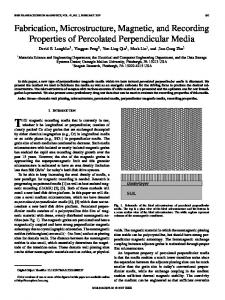
FIG. 1 is a transmission electron microscopic photograph 60
digital recording systems have become predominant as described above. Thus, magnetic recording media are required to have a loW error rate. From the above vieWpoint, 65
medium for digital recording having the eXcellent properties
they are aligned in parallel With the in-plane direction of the magnetic layer along the machine direction. Thus, the stud particulate or ellipsoidal magnetic poWder. As a result, it has been found that G) a high elasticity is achieved in the
As a result of the further studies based on the above
the present invention can provide a magnetic recording
it has been found that the high output can be obtained When a P-V value (in terms of the optical interference type three-dimensional surface roughness) is 50 nm or less. invention are substantially not mechanically oriented so that
its good recording properties even at a coercive force of about 80 kA/m.
?ndings, it has been found that a magnetic recording medium having the folloWing characteristics can exhibit remarkable characteristics. With the recent trend to the high recording density, the
In the system using the recording With a short Wavelength of 1.0 pm for the purpose of the high density recording, the
have been improved to attain the high output. As a result, F)
very quick reversal of magnetiZation so that the range of the reversal of magnetiZation is narroWed. Accordingly, such a
magnetic recording medium has much better recording characteristics than magnetic recording media comprising the conventional acicular magnetic poWders. Furthermore, the magnetic recording medium according to the present
In the case of the magnetic recording media comprising the conventional acicular magnetic poWders, since the mag netic poWder particles are mechanically oriented in a spe ci?c direction, a certain deorientation treatment is necessary.
Furthermore, it has been revealed that the rare earth element
ellipsoidal ?ne particles.
saturated magnetic ?uX density is from 0.1 to 0.5 T, in any
perpendicular to the magnetic layer plane.
properties, and that a high recording density magnetic rare earth element-iron-boron magnetic poWder.
When the magnetic recording medium of the present invention is used in a disc form, it is preferable that E) the magnetiZation-easy-directions are randomly distributed in the magnetic layer plane, and that a coercive force is from 60 to 380 kA/m, a squareness is from 0.4 to 0.7, and a
it has been found that only a rare earth element-iron-boron
magnetic poWder comprising a rear earth metal, iron and boron and having a speci?c structure satis?es all these
direction is in a direction perpendicular to the magnetic layer plane, a coercive force is from 60 to 320 kA/m,
(magni?cation: 100,000 times) of the neodymium-iron boron magnetic poWder having particulate or ellipsoidal particles, Which is produced in EXample 1. EMBODIMENTS FOR CARRYING OUT THE INVENTION
With the conventional acicular iron-cobalt alloy magnetic poWder, Which is used for high density coating type mag
US 6,517,934 B1 7
8
netic recording medium, the coercive force (1) is reaching
comparison With the rare earth element-iron-boron magnetic
the theoretical limit among the above basic properties (1) through In connection With the particle siZe (5), it is dif?cult to disperse the poWder in a binder, if the particle siZe
materials for the permanent magnets. Hitherto, neodymium attracts attention as the rare earth element, but rare earth
elements other than neodymium can be used for the mag
is further decreased from the current particle siZe. In addition, the most serious problem is that it is impossible to
netic recording media.
achieve the properties (4) and (6) at the same time, because
neodymium, for example, samarium, terbium, yttrium, etc.
the acicular ratio can be reduced only to about 5 since the
can achieve the same effects as neodymium Which is knoWn
coercive force is based on the shape anisotropy, that is, the acicular shape, and if the acicular ratio is further decreased to less than 5, the uniaXial anisotropy deteriorates and thus
The reason Why the rare earth elements other than
as the rare earth element constituting the permanent magnets 10
the coercive force becomes too small.
From the vieWpoint different from the magnetic poWders based on the shape magnetic anisotropy, the present inven tors have synthesiZed various magnetic poWders to improve the magnetic properties in accordance With the above described basic guideline, and checked the magnetic anisot ropy of the magnetic poWders. Then, it has been found that
has not bee clari?ed, but it may be presumed that, When the particle siZe is very small like the magnetic poWder of the present invention, the surface effects may be intensi?ed, and thus the reaction among the rare earth element, a transition metal and boron may be eXcited.
15
That is, according to the present invention, the rare earth element-iron-boron magnetic materials, Which have been regarded and studied as the permanent magnet materials, can be practically used as the magnetic materials for the mag netic recording media in the coercive force range loWer than that of the permanent magnets.
the rare earth element-iron-boron magnetic materials com prising a rare earth element, iron and boron as constituent
elements have large crystalline magnetic anisotropy, and
According to the present invention, the high coercive
therefore it is not necessary to form the particles in an
force is achieved in the range Where the recorded signals can
acicular shape and that, When the particles are in the particulate or ellipsoidal shape, the magnetic poWder has a large coercive force in one direction. Herein, the ellipsoidal magnetic poWder particles mean those having a ratio of the
be erased With the magnetic head, and also the eXcellent electromagnetic conversion characteristics as the thin layer
25
major aXis to the minor aXis of 2 or less. Therefore, the
boron magnetic poWder having an average particle siZe of 5 to 200 nm is produced by greatly decreasing the content of
magnetic poWder particles of the present invention have essentially different shapes from those of the conventional
the rare earth element from the composition knoWn for the materials of the permanent magnets or forming the core parts of the magnetic poWder particles from metal iron or an
poWder particles for the magnetic recording media. The rare earth element-iron-boron magnetic materials are
knoWn as high performance magnetic materials comprising particles of a submicron order, Which are produced by
poWder metallurgical methods. For eXample, a neodymium-iron-boron magnetic material for a permanent magnet has a composition represented by
iron alloy While forming the shell parts of the particles from 35
the rare earth element-iron-boron magnetic material. As the rare earth element contained in such magnetic poWders, at least one element selected from the group
consisting of yttrium, ytterbium, cesium, praseodymium, samarium, lanthanum, europium, neodymium and terbium is used. Among them, When neodymium, samarium, yttrium or
Nd2Fe14B, and a very large coercive force of 800 kA/m or
more. HoWever, the coercive force of the magnetic recording medium is determined in relation With a magnetic head, and it is said that the recording is possible With magnetic recording media having a coercive force Which is up to about one siXth (1/6) of the saturated magnetic ?uX density of the magnetic head. Therefore, it is impossible to erase the recorded signals With the magnetic head When the magnetic poWder has such a high coercive force as described above, and thus the magnetic poWder cannot be used as a magnetic
coating type magnetic recording media can be attained, When the particulate or ellipsoidal rare earth element-iron
terbium is used, a high coercive force can be easily attained. When the speci?c rare earth element-iron-boron magnetic
poWder is used to produce the thin layer coating type magnetic recording media, the high coercive force and the high saturation magnetiZation can be achieved at the same 45
time. That is, this type of the magnetic poWder has the speci?c high saturation magnetiZation, since it contains the greatly decreased amount of the rare earth element and
poWder for the magnetic recording media.
predominantly metal iron or the iron alloy. In particular, it has the highest saturation magnetiZation When the core part
The rare earth element-iron-boron magnetic material hav
ing the composition of Nd2Fe14B has the very high coercive
of the particle is formed from metal iron or an iron alloy, in
force as described above. According to the present
particular, the iron-cobalt alloy.
invention, When samarium (Sm), terbium
Metal iron or the iron alloy alone has a loW coercive force, since it has no shape anisotropy, but When the small amounts
or yttrium
(Y) is used as a rare earth element in place of Nd, the magnetic poWder has a coercive force suf?cient for use in
the magnetic recording media. Since the rare earth element-iron-boron magnetic mate rials have attracted attentions as permanent magnet materials and have been studied, it has been revealed that Nd—Fe—B
magnetic materials have particularly large magnetic anisotropy, and practically used. HoWever, When the rare earth element-iron-boron magnetic materials are used in the
magnetic recording media, the coercive force of the perma nent magnets is too large and thus the recorded signals cannot be erased With the magnetic head. To achieve a
coercive force suitable for the magnetic recording media, it is effective to decrease the amount of the rare earth element
and increase the amount of boron in relation to iron, in
of the rare earth metal and boron are added thereto, the 55
coercive-force greatly increases. In addition, When the core part of the particle is formed from metal iron or an iron alloy While the shell part surrounding the core part is formed from the rare earth element-iron-boron material, the magnetic poWder has the large coercive force as a Whole, since this material has the large coercive force. In this case, the material itself has a relatively loW saturation magnetiZation, but the high saturation magnetiZation of metal iron or the iron alloy is maintained. As a result, the high saturation magnetiZation and the high coercive force are achieved at
65 the same time.
The speci?c rare earth-iron-boron magnetic poWder used according to the present invention may integrate the mag
US 6,517,934 B1 9
10 NoW, the particle shape of the rare earth element-iron
netic anisotropy of metal iron or the iron alloy and the magnetic anisotropy of the rare earth element-iron-boron
boron magnetic poWder is explained from the vieWpoint of the dispersion of the poWder in the magnetic paint and the properties required to form the thin magnetic layer.
material through the magnetic interaction, and may behave like a single magnetic material to exhibit the good electro magnetic properties even When it has the particle structure consisting of the core part and the shell part. The combina tion of a plurality of magnetic anisotropies in the particle
In the case of the conventional acicular magnetic
poWders, the particle siZe is decreased to improve the recording properties such as the decrease of noise. As a
result, the speci?c surface area of the particles inevitably
through the magnetic interaction is ?rstly found in the present invention. As a result of the studies on the particle siZe of the rare
10
earth element-iron-boron magnetic poWder, it has been
found that the magnetic layer has good magnetic properties
When the magnetic poWder is dispersed in the binder. Furthermore, When the magnetic paint dispersion is diluted With a large amount of an organic solvent to apply a thin
When the average particle siZe of the material is in the range
layer, the magnetic poWder particles tend to agglomerate,
betWeen 5 and 200 nm. With the conventional acicular
magnetic poWder, the loWer limit of the average particle siZe
increases. Thus, the interaction With the binder increases so that it becomes dif?cult to obtain a homogeneous dispersion
and therefore the orientation and surface properties deterio 15
rate. Consequently, the particle siZe of the magnetic poWder,
is about 0.1 pm to maintain the high coercive force.
Which can be used in the production of the coating type
HoWever, the magnetic poWder of the present invention can
magnetic recording media, is limited.
be made very ?ne to have the average particle siZe of at least
In contrast to the conventional magnetic poWders, the rare
5 nm, and such ?ne particles can exhibit good magnetic properties, since the coercive force is mainly based on the
earth element-iron-boron magnetic poWder of the present invention has the particulate or acicular particle shape, and
20
crystalline magnetic anisotropy. In particular, the average
thus it can have a shape close to a sphere having the smallest
particle siZe is preferably at least 8 nm, more preferably at
speci?c surface area. Therefore, in comparison With the
least 10 nm.
conventional magnetic poWders, the magnetic poWder of the
When the average particle siZe of the magnetic poWder is too large, the ?lling properties of the magnetic poWder in the magnetic layer deteriorate, and also the surface properties
present invention has a small interaction With the binder and 25
deteriorate When the magnetic layer is made thin. In addition, the particle noise due to the particle siZe increases
When the magnetic recording medium is produced using such a magnetic poWder having a large average particle siZe.
30
The decrease of the thickness of the magnetic layer is effective to suppress the decrease of the output due to the 35
in the transmission electron microscopic (TEM) photograph taken at a magni?cation of 100,000 times and averaging the
measured particle siZes.
40
When the iron alloy is selected from metal iron and the iron alloy Which contribute to the increase of the saturation magnetiZation in the rare earth element-iron-boron magnetic
poWder, examples of metals Which form alloys With iron include magnetic transition metals such as Mn, Zn, Ni, Cu, Co, etc. Among them, Co and Ni are preferable. In particular, Co is preferable since it can increase also the saturation magnetiZation. The amount of the transition metal is preferably from 5 to 50 atomic %, more preferably from
sion of the particles is easy. Thus, the magnetic poWder of the present invention can provide the magnetic paint Which is particularly suitable for the formation of the thin magnetic layer. As a result, the magnetic poWder having the average particle siZe of about 5 nm can be practically used.
Accordingly, the average particle siZe should be 200 nm or less and is preferably 100 nm or less, more preferably 50 nm or less. When the average particle siZe is adjusted in such a
range, the very high ?lling properties are attained, and the excellent saturated magnetic ?ux density is achieved. Herein, the average particle siZe of the magnetic poWder is obtained by measuring the particle siZes of 500 particles
can provide a magnetic paint With good ?oWability. If the
magnetic poWder particles are agglomerated, the redisper
45
Writing and reading demagnetiZation, Which is the essential problem of the longitudinal recording. Insofar as the acicular magnetic poWder having the particle siZe of about 0.1 pm is used, the thickness of the magnetic layer is limited, because the acicular particles are aligned in the plane direction of the magnetic recording medium on the average by the orienta tion in the magnetic ?eld, but some particles may be aligned in the direction perpendicular to the plane of the medium since the orientation of the particles has distribution. When such particles are contained, they protrude from the surface of the magnetic layer and deteriorate the surface properties of the medium and may increase noise. Such problems become more serious as the thickness of. the magnetic layer decreases. Thus, it is difficult to produce the coated ?lm having a thickness of about 0.3 pm or less and also the
smooth surface, insofar as the acicular magnetic poWder is 50
10 to 30 atomic %, based on iron. The amount of the rare earth element constituting the rare earth element-iron-boron material is from 0.2 to 20 atomic
used. When an undercoat layer is provided betWeen the non
magnetic support and the magnetic layer to reduce the thickness of the magnetic layer as explained beloW, and the
%, preferably from 0.3 to 15 atomic %, more preferably from 0.5 to 10 atomic %, based on iron in the While magnetic poWder. The amount of the boron is from 0.5 to 30 atomic %, preferably from 1 to 25 atomic %, more preferably from 2 to 20 atomic %, based on iron in the Whole magnetic poWder. The atomic percentages of the rare earth element
55
and boron are measured by the X-ray ?uorescence analysis.
60
undercoat layer is formed by the simultaneous multiple layer coating method in Which the magnetic paint for the magnetic layer containing the dispersed acicular magnetic poWder is coated over the undercoat layer While the undercoat layer is
still Wet, the magnetic poWder is entrained by the undercoat layer so that the acicular magnetic poWder particles tend to penetrate into the undercoat layer at the interface betWeen
When the above amounts of the rare earth metal and boron are contained in the material, the bonds of the atoms in the
the magnetic poWder and the undercoat layer. Thus, the orientation of the magnetic poWder particles is further
particles are enhanced by the magnetic interaction of a
disturbed, so that the desired squareness is not attained, and
plurality of magnetic anisotropies, and thus the particles are united so that the coercive force of 80 to 400 kA/m, Which
is most suitable as the magnetic poWder for the high per formance magnetic recording media, can be achieved.
the surface smoothness of the magnetic layer deteriorates. 65
Accordingly, the above problem may be one of the causes for a bar to the increase of the recording density by the thin
layer coating When the acicular magnetic poWder is used.
US 6,517,934 B1 11
12
element-iron-boron magnetic powder of the present inven
sample-vibration type magnetometer at 25° C. in an applied magnetic ?eld of 1,273.3 kA/m and compensated using a
tion has a small particle siZe and also the particulate or
standard sample.
In contrast to the acicular magnetic powder, the rare earth
ellipsoidal particle shape and can have the particle shape close to the sphere. Therefore, the poWder particles do not protrude from the surface of the magnetic layer. When the undercoat layer is provided, the penetration of the magnetic poWder particles into the undercoat layer can be suppressed in contrast With the acicular magnetic poWder. Accordingly, the magnetic layer having the extremely smooth surface can
The rare earth element-iron-boron magnetic poWder of the
present invention may be prepared by the folloWing method: Firstly, an aqueous solution containing the rare earth element ion such as neodymium, samarium, etc., the iron ion and optionally a transition metal ion such as Mn, Zn, Ni, Cu, Co, etc., and an aqueous solution of an alkali are mixed to 10
be formed.
As the thickness of the magnetic layer decreases, the magnetic ?ux from the magnetic layer decreases and thus the output decreases. Since the magnetic poWder of the present invention has the particulate or ellipsoidal particle shape and can have the particle shape close to the sphere, it
optional transition metal. As the sources of the rare earth
element ion, iron ion and transition metal ion, iron sulfate, iron nitrate and the like are used. 15
has an advantage such that the magnetic poWder can be contained in the magnetic layer at a higher ?lling rate than
Next, a boron compound is mixed With the coprecipitate, and the mixture is heated at a temperature of 60 to 400° C. to obtain the oxide of the rare earth metal, iron and option
ally the transition metal containing boron. The boron compound serves as the source of boron and
the acicular magnetic poWder and thus the high magnetic ?ux density can be easily attained. Furthermore, With respect to the saturation magnetiZation, in general, the metal or metal alloy magnetic poWders have the larger speci?c surface area as the particle siZe decreases,
form the coprecipitate of the rare earth element, iron and the
20
so that the ratio of the surface oxide layer Which does not
contribute to the saturation magnetiZation increases, While the magnet part contributing to the saturation magnetiZation decreases. That is, as the particle siZe decreases, the satu ration magnetiZation decreases. This tendency is remarkable With the acicular magnetic poWders, and the saturation
25
magnetiZation suddenly decreases, When the major axis of
30
also functions as a ?ux Which facilitates the crystal groWth
to the desired particle siZe While preventing the excessive sintering of the particles. The kind of the boron compound is not limited. Preferably, H3BO3, BO2, etc. are used. Although the boron compound in the solid state may be mixed With the coprecipitate, the boron compound is dis solved in the aqueous suspension of the coprecipitate, the suspension is dried to remove Water, and then the residue is heated so that the coprecipitate and boron are homoge
neously mixed. Thereby, the magnetic poWder having the better properties can be obtained.
the acicular particle is 0.1 pm or less. Such decrease of the
The heated mixture is Washed With Water to remove the
saturation magnetiZation is taken into consideration, When the limit of the usable particle siZe is determined. Since the rare earth element-iron-boron magnetic poWder of the present invention has the particular or ellipsoidal particle shape, the speci?c surface area is minimum among the particles having the same volume. Therefore, the magnetic poWder of the present invention can maintain the high saturation magnetiZation in spite of the ?ne particle. In the present invention, the particle shape of the rare
excessive boron, dried and then reduced by heating in a reducing atmosphere such as hydrogen gas at a temperature of 400 to 800° C. to obtain the rare earth element-iron-boron 35
magnetic poWder. The magnetic poWder of the present invention may con tain other element to improve, for example, corrosion resis tance. In this case, the amounts of the rare earth element and
40
boron in the Whole magnetic poWder are preferably from 0.2 to 20 atomic % and from 0.5 to 30 atomic %, respectively,
earth element-iron-boron magnetic poWder is expressed by
based on iron.
“particulate or ellipsoidal”. This intends to include any
Alternatively, the rare earth element-iron-boron magnetic poWder of the present invention may be produced as fol loWs: An aqueous solution containing the iron ion and option ally the transition metal ion such as Mn, Zn, Ni, Cu, Co, etc.
shape from substantially particulate to the ellipsoid includ ing any intermediate shapes betWeen the particle and the ellipsoid. That is, the above expression is intended to exclude the “acicular” shape of the conventional magnetic poWders. Among various shapes, a sphere having the small
45
and an aqueous solution of an alkali are mixed to form a
est speci?c surface area to an ellipsoid are preferable. The
particle shapes can be observed using the scanning electron
microscope.
precipitate of iron and the optional transition metal. Also in 50
As explained above, the rare earth element-iron-boron
magnetic poWder of the present invention has the saturation
magnetiZation, coercive force, particle siZe and particle shape, all of Which are essentially suitable to form the thin
55
this method, iron sulfate, iron nitrate and the like are used as the sources of the iron ion and transition metal ion. Then, the salt of the rare earth element such as neodymium, samarium, etc. and the boron compound are mixed With the precipitate, and the mixture is heated at a temperature of 60 to 400° C. to obtain the oxide of the rare earth metal, iron and option
magnetic layer, and particularly good Writing-reading char
ally the transition metal containing boron.
acteristics can be achieved, When the magnetic recording medium having the magnetic layer With an average thick
Next, excessive boron is removed, and the oxide is heated and reduced in the hydrogen gas like the above-described
ness of 0.3 pm or less is produced using such a magnetic
poWder. Among the magnetic poWders of the present
method to obtain the rare earth element-iron-boron magnetic 60
invention, those having a saturation magnetiZation of 10 to 25 pWb/g are preferably used to improve the characteristics in the high recording density range in the case of the
The latter method is suitable to obtain the rare earth
element-iron-boron magnetic poWder having a structure comprising a core part mainly formed of metal iron or the
magnetic recording medium having the magnetic layer With the average thickness of 0.3 pm or less.
Herein, the coercive force and saturation magnetiZation of the magnetic poWder are values, Which are measured With a
poWder.
iron alloy With the transition metal and an outer part mainly 65
formed of the rare earth element-iron-boron material. Also in
this method, the magnetic poWder of the present invention may contain other element to improve, for example, corro
US 6,517,934 B1 13
14
sion resistance. Again, the amounts of the rare earth element
abrasive) may be used. Among them, alumina particles are preferred, and examples of the commercially available alu mina particles are “AKP-10”, “AKP-12”, “AKP-15”, “AKP 30”, “AKP-50”, “HIT-82” and “HIT-60 (all available from Sumitomo Chemical Co., Ltd.), “UB 40B” (manufactured by Murakami Industries, Ltd.), and the like. The particle siZe of the abrasive is preferably from 0.01 to 1 pm. If necessary, abrasives having different particles siZes,
and boron in the Whole magnetic powder are preferable from 0.2 to 20 atomic % and from 0.5 to 30 atomic %, respectively, based on iron.
In the magnetic recording medium of the present
invention, the magnetic layer is formed by mixing and dispersing the rare earth element-iron-boron magnetic poWder, the binder and usually additives such as an abrasive, a dispersant, a lubricant, etc. as Well as carbon black in an
organic solvent to obtain the magnetic paint, applying the
10
magnetic paint on the non-magnetic support With or Without
inserting the undercoat layer betWeen them, and drying the
applied magnetic paint.
or a single abrasive having a particle siZe distribution may be used to achieve the same effects. The particle shape of the abrasive may be a needle form, a sphere, a cube, etc. and those having a corner in the shape are preferable since the
abrasive having such shape has high abrading properties.
nation of a polyurethane resin and at least one resin selected 15
The amount of the abrasive is usually from 6 to 20 Wt. parts, preferably from 8 to 15 Wt. parts, per 100 Wt. parts of the
from the group consisting of vinyl chloride resins, vinyl chloride-vinyl acetate copolymer resins, vinyl chloride
conversion properties and the contamination of the magnetic
The binder used in the magnetic layer may be a combi
magnetic poWder from the vieWpoint of the electromagnetic head. Examples of the method for adding the abrasives such as
vinyl alcohol copolymer resins, vinyl chloride-vinyl acetate maleic anhydride copolymer resin, vinyl chloride hydroxyalkyl acrylate copolymer resins and nitrocellulose
alumina poWder include a method comprising adding the abrasive directly to the magnetic paint containing the mag netic poWder and the binder in the kneading step using a
resins. Among them, the polyurethane resin and the vinyl chloride-hydroxyalkyl acrylate copolymer resin are prefer ably used in combination. Examples of the polyurethane
resin include polyester plyurethane, polyether polyurethane,
polyetherpolyester polyurethane, polycarbonate
kneader or the pre-mixing step in the course of the prepa 25
polyurethane, polyesterpolycarbonate polyurethane, etc. Preferably, the binder resins have a functional group to
improve the dispersibility of the magnetic poWder and increase the ?lling rate of the magnetic poWder. Examples of the functional group include —COOM, —SO3M,
30
—OSO3M, —P=O(OM)3, —O—P=O(OM)2 (Wherein M
ration of the magnetic paint; a method comprising separately preparing a dispersion containing the abrasive and adding the dispersion to the magnetic paint; etc. The former method, Which requires no separate step, is preferably used from the vieWpoint of the productivity. As one of the additives, a dispersant is preferably used.
Examples of the dispersant include nonionic surfactants such as alkylene oxide base surfactants, glycerin base
is a hydrogen atom, an alkali metal or an amine group),
surfactants, glycidol base surfactants, alkylphenol-ethylene
—OH, —NR2, —NJ'R3 (Wherein R is a hydrogen atom or a
oxide adducts, etc.; cationic surfactants such as cyclic
hydrocarbon group), an epoxy group, etc. When tWo or more 35
amines, ester amides, quaternary ammonium salts, hydan
resins are used in combination, they preferably have the
toin derivatives, heterocyclic compounds, phosphonium
same functional group.
salts, sulfonium salts, etc.; anionic surfactants having an
The amount of the binder is usually from 5 to 50 Wt. parts, preferably from 10 to 35 Wt. parts, based on 100 Wt. parts of
acid group such as a carboxylic acid group, a sulfonic acid group, a phosphoric acid group, a sulfate ester group, a
the magnetic poWder. In particular, When the vinyl chloride
40
resin is used as the binder, its amount is from 5 to 30 Wt.
parts, and When the polyurethane resin is used, its amount is from 2 to 20 Wt. parts. Most preferably, the vinyl chloride resin and the polyurethane resin are used in combination in the above amounts. It is preferable to use the binder in combination With a
As other dispersants, Ti-containing dispersants, 45
P-containing dispersants, etc. may be used. Examples of the Ti-containing dispersants are titanate coupling agents such as “PLENACT KR-38S”, “PLENACT KR-TTS”,
thermally curing crosslinking agent Which bonds With the
“PLENACT KR-46B”, “PLENACT KR-55”, “PLENACT KR-41B”, “PLENACT KR-138S”, “PLENACT KR-238S”, “PLENACT KR-44” and “PLENACT KR-9SA” (all avail
functional group in the binder to crosslink the binder resin.
Preferable examples of the crosslinking agent include poly isocyanates such as isocyanates (e.g. tolylenediisocyanate,
phosphate ester group, etc.; amphoteric surfactants such as amino acids, aminosulfonic acid, sulfate or phosphate esters of aminoalcohols, etc.; and the like.
hexamethylenediisocyanate, isophoronediisocyanate, etc.),
able from AJINOMOTO). Examples of the P-containing dispersants include alkyl phosphates such as monomethyl
reaction products of such isocyanates With a compound
phosphate, dimethyl phosphate, monoethyl phosphate,
having a plurality of hydroxyl groups (e.g. trimethylolpropane, etc.), condensation products of such
diethyl phosphate, etc.; and aromatic phosphates such as phenyl phosphate, etc. Examples of the commercially avail
50
isocyanates, and the like. The amount of the crosslinking agent is usually from 15 to 70 Wt. parts per 100 Wt. parts of the binder. To increase the strength of the magnetic layer, abrasives With high hardness is preferably used. As the abrasive, there
55
may be used materials having a Mohs hardness of atl least
60
6, for example, ot-alumina having an alphatiZation degree of at least 90%, [3-alumina, silicon carbide, chromium oxide, cerium oxide, ot-iron oxide, corrundom, arti?cial diamond, silicon nitride, silicon carbide, titanium carbide, titanium oxide, silicon dioxide, boron nitride, and mixtures thereof. Furthermore, complexes of these abrasives (for example, an abrasive the particle surfaces of Which are treated With other
able P-containing dispersants are “GARFAC RS410”
(manufactured by TOHO CHEMICAL), “JP-502” and “JP 508” (both manufactured by JOHOKU CHEMICAL INDUSTRIES), etc. A further additive contained in the magnetic layer is preferably a lubricant. Examples of the lubricant include
knoWn fatty acids, fatty acid esters, fatty acid amides, metal salts of fatty acids, hydrocarbon, and mixtures of tWo or more of them. Among them, fatty acids having at least 10 carbon atoms, preferably 12 to 24 carbon atoms are prefer 65
ably used. Such fatty acids partly adhere to the magnetic poWder to facilitate the dispersing of the magnetic poWder and also soften the contact betWeen the medium and the
US 6,517,934 B1 15
16
magnetic head in the initial abrading state to decrease a coefficient of friction. Thus, the fatty acids contribute to the
include a coercive force of from 80 to 400 kA/m, particu larly from 95 to 320 kA/m in the machine direction of the
suppression of the head contamination.
magnetic recording medium, and a saturated magnetic ?ux
The fatty acids may be linear or branched and unsaturated or saturated ones. The linear fatty acids are preferable since
density of from 0.1 to 0.5 T, particularly from 0.2 to 0.4 T, When the magnetiZation-easy-axis is in the machine direc tion. When the magnetiZation-easy-axis is in the direction perpendicular to the magnetic layer, the coercive force in the perpendicular direction is preferably from 60 to 320 kA/m, particularly from 70 to 300 kA/m, and the saturated mag netic ?ux density is preferably from 0.1 to 0.5 T, more preferably from 0.2 to 0.5 T. Furthermore, in the case of the
they have good lubrication properties. Examples of the linear fatty acids include lauric acid, myristic acid, stearic acid, palmitic acid, oleic acid, isostearic acid, etc. The amount of the dispersant is preferably from 0.5 to 5 Wt. parts, more preferably from 1 to 4 Wt. parts, per 100 Wt.
parts of the magnetic poWder. The amount of the lubricant is preferably from 0.2 to 10 Wt. parts, more preferably from 0.5 to 5 Wt. parts, per 100 Wt. parts of the magnetic poWder. To decrease the coefficient of friction of the magnetic layer and prevent the electrostatic charge, carbon black is preferably used. Examples of the carbon black include furnace black for rubbers, thermal black for rubbers, carbon black for coloring, acetylene black, etc. The carbon black
10
magnetic recording medium in Which the magnetiZation 15
preferably has a speci?c surface area of 5 to 500 m2/g, a DBP oil absorption of 10 to 400 ml/100 g, a particle siZe of 5 to 400 nm, pH of 2 to 10, a Water content of 0.1 to 10 Wt.
a sample-vibration type magnetometer at 25° C. in an external magnetic ?eld of 1273.3 kA/m like in the case of the
%, and a tap density of 0.1 to 1 g/cc. Examples of the commercially available carbon black are “SEVACARB
MTCI” (manufactured by Columbian Carbon), “Thermax PoWder N-991” (manufactured by CANCARB), etc.
magnetic poWder With a laminated sample having 20 mag 25
netic layer planes and a diameter of 8 mm. The measured
values are compensated using the standard sample. As explained in the above, When the magnetic recording
The amount of the carbon black added is usually 3 Wt. % or less based on the magnetic poWder.
media are produced using the rare earth element-iron-boron
In the formation of the magnetic layer, any conventionally used organic solvent may be used as the organic solvent
easy-axes are randomly distributed in the plane of the magnetic layer, the coercive force is preferably from 60 to 380 kA/m, particularly from 70 to 300 kA/m, and the saturated magnetic ?ux density is preferably from 0.1 to 0.5 T, particularly from 0.2 to 0.4 T in any directions in the plane of the magnetic layer and also in the direction perpendicular to the magnetic layer. Herein, the above magnetic properties are measured using
magnetic poWder according to the present invention, it does 30
not require such a large saturation magnetiZation as required
Which is used in the preparation of the magnetic paint and the lubricant solution. Examples of the organic solvent
by the acicular magnetic poWder. When the signals are recorded on the magnetic recording media, the domains of
include aromatic solvents (e.g. benZene, toluene, xylene, etc.), ketone solvents (e.g. acetone, cyclohexanone, methyl ethyl ketone, methyl isobutyl ketone, etc.), acetate solvents (e.g. ethyl acetate, butyl acetate, tec.), carbonate solvents (e.g. dimethyl carbonate, diethyl carbonate, etc.), alcohols
the reversal of magnetiZation in the media do not contribute to the output. Thus, such domains are preferably made as small as possible. HoWever, With the conventional acicular magnetic poWder the coercive force of Which is based on the
35
shape magnetic anisotropy, the magnetic interaction among
(e.g. ethanol, isopropanol, etc.), hexane, tetrahydrofuran,
the magnetic poWder particles increases as the saturation magnetiZation increases, and thus a large static magnetic
dimethylformamide, and so on.
In the production of the magnetic recording media of the present invention, any knoWn method for the preparation of paints can be used to form the magnetic layer and the undercoat layer Which Will be described beloW. In particular,
40
energy is accumulated When the reversal of magnetiZation is
45
should be effected sloWly. As a result, the domains of the reversal of magnetiZation extend. In contrast, the coercive force of the rare earth element-iron-boron magnetic poWder is based on the crystalline magnetic anisotropy, and thus the
effected quickly. Therefore, the reversal of magnetiZation
a kneading process using a kneader or the like and a primary
dispersing process are preferably used in combination. In the primary dispersion process, a sand mill is preferably used
magnetic interaction among the magnetic poWder particles is
since the dispersibility of the magnetic poWder is improved
loW. As a result, the reversal of magnetiZation can be
and also the surface properties of the magnetic layer can be
effected quickly. Thus, the domains of the reversal of magnetiZation are narroWed and the large output can be obtained even With the relatively small saturation magneti
controlled.
In the primary dispersing process, Zirconia beads having
50
high hardness are preferably used as dispersing media. As the Zirconia beads used as the dispersing media, those produced by the cold isobar press (CIP) method or the hot isobar press (HIP) method are preferably used. More
preferably, the Zircona beads produced by the HIP method
Zation.
According to the magnetic recording media of the present invention, their properties are remarkably exhibited to solve the decrease of the output due to the demagnetization, Which 55
is the essential problem of the longitudinal recording, When
are used, since they have a density close to the theoretical
the magnetic layer is made thin to have the average thickness
density and thus the beads are hardly cracked by the strong dispersion in the sand mill and the like, and they are uniformly abraded. Examples of such Zirconia beads are
of 0.3 pm or less, preferably from 0.01 to 0.3 pm, more preferably from 0.01 to 0.2 pm. The thickness of the
TORAYCERAM (manufactured by TORAY), ZIRCONIA BALL (manufactured by NIPPON KAGAKU TOGYO),
magnetic layer is determined depending on the recording 60
particularly exhibited When the present invention is applied to the recording system using the shortest recording Wave length of 1.0 pm or less. For example, With the system using
etc. The dispersing time may be suitably adjusted in the range betWeen 30 and 100 minutes in terms of the residence
time of the paint.
The magnetic properties of the magnetic layer, Which is formed as described above and contains the magnetic
poWder, the binder and the other components, preferably
Wavelength used. The effects of the present invention can be
the shortest recording Wavelength of 0.6 pm such as DLT-4, 65
the average thickness of the magnetic layer is preferably about 0.2 pm, and With the system using the shortest recording Wavelength of 0.33 pm such as DDS-3, the
US 6,517,934 B1 17
18
average thickness of the magnetic layer is preferably about 0.1 pm. Thus, the present invention is preferably applied to the systems requiring the very think magnetic layers. From the vieWpoint of the productivity, the loWer limit of the thickness of the magnetic layer is preferably 0.01 pm. The anisotropic magnetic ?eld distribution of the mag netic recording media of the present invention is preferably
the helical scanning system, the tip of the magnetic head is shaped to have an acute angle so that the amount of
indentation in the magnetic layer increases, and the system is designed so that the relative speed of the magnetic tape and the magnetic head is very high. Therefore, the deterio ration of the head contact leads to the deterioration of an
envelope. From such a vieWpoint, to improve the head contact of the medium against the magnetic head, a ratio of a Young’s modulus in the transverse direction (YTD) to that
0.6 or less in the case of the longitudinally oriented magnetic
recording media. When the anisotropic magnetic ?led dis tribution of the magnetic recording media With the longitu
10
dinal orientation is 0.6 or less, the dispersibility and orien
netic poWder particles have the needle-form shape, they are
tation properties of the ?ne particles of the magnetic poWder according to the present invention are improved, so that the output at the short Wavelength is increased and the error rate is improved even When the coercive force is the same.
oriented so that the major axes are in parallel With the plane 15
distribution decreases as the orientation properties of the
Therefore, the strength of the magnetic layer in the machine 20
direction is inevitably stronger than that in the transverse
direction, and the head contact against the magnetic head,
even at random distribution, since it has the better particle siZe distribution than the conventional acicular magnetic
Which is desired to be isotropic, deteriorates. In contrast,
since the magnetic recording media of the present invention use the magnetic poWder particles having the particulate or
poWder. When the magnetic recording media of the present inven tion are used in the high density recording systems With the
of the magnetic layer by the mechanical orientation step When the magnetic paint is applied. In addition, they are oriented in the magnetic ?eld in the machine direction to attain the high squareness. Thus, the major axes of the particles are further aligned in the machine direction.
In general, the value of the anisotropic magnetic ?led magnetic poWder increases, since the former depends on the latter. HoWever, the magnetic poWder of the present inven tion exhibits the good anisotropic magnetic ?led distribution
(YMD) in the machine direction of the medium (YTD/YMD) is preferably from 1.0 to 1.7. Since the conventional mag
25
ellipsoidal shape, the magnetic poWder particles are hardly mechanically oriented in the course of the application of the
shortest recording Wavelength of 1.0 pm or less, a P-V value
magnetic paint in comparison With the acicular magnetic
(in terms of the optical interference type three-dimensional
poWder, and they are less oriented in parallel With the plane of the magnetic layer. As a result, the strength of the
surface roughness) is preferably 50 nm or less, more pref erably 40 nm or less, to achieve the high output. That is, With
the conventional acicular magnetic poWder, When the mag
30
netic recording media are produced to have a multiple
layer-structure having the undercoat layer to decrease the thickness of the magnetic layer, the magnetic poWder par ticles tend to penetrate in the undercoat layer in comparison With the direct application of the magnetic layer on the
35
non-magnetic support. Therefore, the magnetic poWder par ticles are not aligned in parallel With the surface of the magnetic layer, so that the surface properties tends to
deteriorate. HoWever, since the magnetic poWder particles of the present invention have the particulate or ellipsoidal shape, they do not deteriorate the surface properties in the course of the orientation. In addition, although the magnetic poWder of the present invention consists of very ?ne par ticles having an average particle siZe of 5 to 200 nm, it
hardly agglomerates, and thus it has good dispersibility. As
40
45
a result, the magnetic poWder of the present invention can
(manufactured by WYKO) to Which an object head (magni?cation of 40 times) is attached, at a measuring
50
55
The surface roughness is measured 4 times at each measur
magnetic layer can be suppressed. The undercoat layer may contain inorganic poWder, a
Examples of the non-magnetic poWder include ot-alumina having an alphatiZation degree of at least 90%, [3-alumina, y-alumina, ot-iron oxide, TiO2 (rutile or anatase type), TiOx, cerium oxide, tin oxide, tungsten oxide, ZnO, ZrO2, SiO2, Cr2O3, goethite, corundum, silicon nitride, titanium carbide,
magnesium oxide, boron nitride, molybdenum disul?de, copper oxide, MgCO3, CaCO3, BaCO3, SrCO3, BaSO4,
ing point and the measured values are averaged to obtain the 60
silicon carbide, titanium carbide, and mixtures thereof.
Examples of the magnetic poWder include y-Fe2O3, cobalt containing y-Fe2O3, Fe alloys, CrO2, barium ferrite, etc.
Since the magnetic recording medium should be in con tact With the magnetic head With the medium being Wound around the cylinder in the helical scanning system, the
strength of the magnetic recording medium in the machine
applied magnetic paint is improved in comparison to the direct application of the magnetic paint to the non-magnetic
binder, a lubricant, carbon black, and so on. The inorganic
pm>50
78.0
16.2
C. Ex. 2 Nd—Fe
3.3
—
—
—
— Irregular
>50
83.6
13.8
C. Ex. 3 Sm—Fe
—
3.0
—
—
— Irregular
>50
85.9
15.3
C. Ex. 4 Fe
—
—
—
—
— Sintered
Submicron
2.4
24.6
Submicron
C. Ex. 5 Fe—Co
—
—
41.4
—
— Sintered
4.0
28.6
C. Ex. 6 Fe—B
—
—
—
—
5.6 Sphere to Ellipsoid
40
42.9
18.2
C. Ex. 7 Fe—Co—B
—
—
42.0
—
6.1 Sphere to Ellipsoid
30
70.0
19.9
The obtained iron-boron magnetic poWder contained 5.6
atomic % of boron based on iron.
The obtained iron-boron magnetic poWder Was observed 60 With a transmission electronmicroscope (magni?cation: 100,
000 times). The magnetic poWder consisted of substantially spherical or ellipsoidal particles, and had an average particle
The magnetic poWder had a saturation magnetiZation of measured With applying a magnetic ?eld of 1,273.3 kA/m.
Example 15 The folloWing components for an undercoat layer Were
siZe of 40 nm.
18.2 pWb/g and a coercive force of 42.9 kA/m When
Examples 15_25 and Comparanve Examples 8_13
kneaded With a kneader and dispersed With a sand mill in a 65
residence time of 60 minutes. To the mixture, a polyisocy anate (6 parts) Was added, stirred and then ?ltrated to obtain an undercoat paint.
US 6,517,934 B1 33
34
Separately, the following components (1) for a magnetic paint were kneaded with a kneader and dispersed with a same mill in a residence time of 45 minutes. To this mixture,
the components (2) for the magnetic paint were added,
parts
stirred and ?ltrated to obtain a magnetic paint.
Carbon black (av. particle size: 25 nm) Carbon black (av. particle size: 370 nm)
40.5 0.5
Barium sulfate Nitrocellulose
4.05 28
Polyurethane resin (containing SO3Na groups)
parts
Titanium oxide powder (av. particle size: 0.035 ,um) Titanium oxide powder (av. particle size: 0.1 ,um) Carbon black (av. particle size: 0.075 ,urn) Vinyl chloride copolymer
10
70 10 20 10
(SO3Na groups: 0.7 x 10’4 eq./g)
Polyester polyurethane resin
5 15
(SO3Na groups: 1.0 x 10’4 eq./g)
Methyl ethyl ketone
130
Toluene
1 1.5
Cyclohexanone
100
Toluene
100
Methyl ethyl ketone
100
The produced magnetic sheet was planish ?nished with ?ve-stage calendering (at 70° C. under a linear pressure of 147 kN/m) and aged at 60° C., 40%RH for 48 hours with winding the sheet around a sheet core. Then, the sheet was slit at a width of 3.8 mm, and the surface of the magnetic layer of the. obtained tape was abraded with a ceramic wheel
80
Myristic acid Butyl stearate
20
Cyclohexanone
65
(a rotation speed of +150% and a winding angle of 30 20
degrees) while traveling the tape at a rate of 100 m/min. Thus, a magnetic tape having a length of 125 m was obtained. The magnetic tape was installed in a cartridge and used as a tape for a computer.
parts
Neodymium-iron-boron magnetic powder of Example 1
100
25
Example 16 A magnetic tape was produced in the same manner as in
(Nd: 2.4 atomic %, B: 9.1 atomic %, based on iron; Coercive force: 191.8 kA/m; Saturation magnetization: 16.6 ,uWb/g; Av. particle size: 25 nm;
Example 15 except that the thickness of the magnetic layer after drying and calendering was changed to 0.28 pm.
Sphere to ellipsoid)
Vinyl chloride-hydroxypropyl acrylate copolymer
8
30
(SO3Na groups: 0.7 x 10’4 eq./g)
Polyester polyurethane resin
4
(SO3Na groups: 1.0 x 10’4 eq./g)
ot-Alumina (av. particle size: 0.4 mm)
Example 15 except that the thickness of the magnetic layer
10
Carbon black (av. particle size: 100 nm) Myristic acid Methyl ethyl ketone
1.5 1.5 133
Toluene
100
Example 17 A magnetic tape was produced in the same manner as in
after drying and calendering was changed to 0.09 pm. 35
Example 18 A magnetic tape was produced in the same manner as in
40
Example 15 except that the neodymium-iron-boron mag netic powder of Example 3 (coercive force: 162.3 kA/m, saturation magnetization: 16.1 pWb/g, average particle size: 15 nm, particle shape: sphere to ellipsoid) was used as a
parts
magnetic powder, and the thickness of the magnetic layer Stearic acid
Polyisocyanate Cyclohexanone Toluene
1.5
after drying and calendering was changed to 0.18 pm.
4 133 33
45
Example 19 A magnetic tape was produced in the same manner as in
Example 18 except that the thickness of the magnetic layer The undercoat paint was applied on a polyethylene
after drying and calendering was changed to 0.11 pm.
terephthalate ?lm (Degrees of thermal shrinkage of 0.8% and 0.6% in the machine and transverse directions, respec tively after heating at 105° C. for 30 minutes) as a non magnetic support to form an undercoat layer having a thickness of 2 pm after drying and calendering. On the
undercoat layer, the magnetic paint was applied while apply ing a magnetic ?eld of 0.3 T along the machine direction so that the magnetic layer had a thickness of 0.12 pm after
50
A magnetic tape was produced in the same manner as in
Example 18 except that the thickness of the magnetic layer after drying and calendering was changed to 0.07 pm 55
Next, on the surface of the non-magnetic support opposite 60
magnetic powder, the thickness of the magnetic layer after drying and calendering was changed to 0.12 pm.
dispersing the following components with a sand mill in a
mixture.
Example 15 except that the samarium-iron-boron magnetic powder of Example 7 (coercive force: 156.0 kA/m, satura tion magnetization: 16.5 pWb/g, average particle size: 15 nm, particle shape: sphere to ellipsoid) was used as a
calendering, and dried. The back coat paint was prepared by
residence time of 45 minutes, adding a polyisocyanate (8.5 parts) to the mixture and then stirring and ?ltrating the
Example 21 A magnetic tape was produced in the same manner as in
drying and calendering, and then dried. to the surface on which the undercoat layer and the magnetic layer were formed, a back coat paint was applied so that the back coat layer had a thickness of 0.7 pm after drying and
Example 20
65
Example 22 A magnetic tape was produced in the same manner as in
Example 15 except that the neodymium-iron-cobalt-boron
US 6,517,934 B1 35
36
magnetic powder of Example 10 (coercive force: 174.3 kA/m, saturation magnetization: 19.7 pWb/g, average par
Example 25 A magnetic tape Was produced in the same manner as in
ticle siZe: 20 nm, particle shape: sphere to ellipsoid) Was used as a magnetic poWder, the thickness of the magnetic layer after drying and calendering Was changed to 0.11 pm.
Example 15 except that no undercoat layer Was formed, the
magnetic paint of Example 18 (magnetic poWder: neodymium-iron-boron type, coercive force: 162.3 kA/m, saturation magnetiZation: 16.1 pWb/g, average particle siZe: 15 nm, particle shape: sphere to ellipsoid) Was applied
Example 23 A magnetic tape Was produced in the same manner as in Example 15 except that the same undercoat as that of
Example 15 Was formed, and then the magnetic paint of
directly on the support ?lm While applying a magnetic ?eld 10
Example 18 (magnetic poWder: neodymium-iron-boron type, coercive force: 162.3 kA/m, saturation magnetiZation: 16.1 pWb/g, average particle siZe: 15 nm, particle shape: sphere to ellipsoid) Was applied on the undercoat layer
of 0.3 T in the machine direction so that the thickness of the
magnetic layer after drying and calendering Was 0.51 pm.
Comparative Example 8 A magnetic tape Was produced in the same manner as in
thickness of the magnetic layer after drying and calendering
Example 15 except that an acicular iron-cobalt alloy mag netic poWder (Co: 24.6 atomic % based on iron; coercive
Was 0.12 pm.
force: 189.4 kA/m, saturation magnetiZation: 18.3 pWb/g,
Without the orientation With the magnetic ?eld so that the
15
average major axis length: 150 nm, acicular ratio: 5) Was used as a magnetic poWder in the magnetic paint and the
In Examples 15 and 18, the coated magnetic paint Was subjected to the orientation treatment in the machine direc tion With the magnetic ?eld to achieve the high squareness in the machine direction, While in Example 23, no orienta
20
thickness of the magnetic layer after drying-and calendering Was changed to 0.50 pm.
tion treatment With the magnetic ?eld Was carried out so that the same level of squareness could be attained in any
directions including the machine and perpendicular direc tions.
Comparative Example 9 25
In general, since the conventional magnetic poWder par
A magnetic tape Was produced in the same manner as in
Comparative Example 8 except that the thickness of the magnetic layer after drying and calendering Was changed to 0.35 pm.
ticles have an acicular shape, they are oriented in the machine direction to some extent in the absence of the
orientation treatment With the magnetic ?eld. HoWever,
since the magnetic poWder particles of the present invention
Comparative Example 10 30
A magnetic tape Was produced in the same manner as in
have a spherical or ellipsoidal shape, they are less in?uenced by the mechanical orientation and thus the same level of squareness can be easily attained in any directions.
Example 24
Comparative Example 8 except that the thickness of the
magnetic layer after drying and calendering Was changed to 0.20 pm 35
Comparative Example 11
A magnetic tape Was produced in the same manner as in Example 15 except that the same undercoat as that of
A magnetic tape Was produced in the same manner as in
Example 15 Was formed, and then the magnetic paint of
Example 18 (magnetic poWder: neodymium-iron-boron
40
type, coercive force: 162.3 kA/m, saturation magnetiZation: 16.1 pWb/g, average particle siZe: 15 nm, particle shape: sphere to ellipsoid) Was applied on the undercoat layer While applying a magnetic ?eld of 0.3 T in the direction perpen dicular to the coated magnetic paint layer so that the
Example 15 except that the neodymium-iron magnetic poW der of Comparative Example 1 (coercive force: 78.0 kA/m, saturation magnetiZation: 16.2 pWb/g, average particle siZe: >50 nm) Was used as a magnetic poWder in the magnetic
paint and the thickness of the magnetic layer after drying and calendering Was changed to 0.28 pm. 45
Comparative Example 12
50
Example 15 except that the iron-cobalt-boron magnetic poWder of Comparative Example 7 (coercive force: 70.0 kA/m, saturation magnetiZation: 19.9 pWb/g, average par
thickness of the magnetic layer after drying and calendering
A magnetic tape Was produced in the same manner as in
Was 0.15 pm.
In Examples 15 and 18, the coated magnetic paint Was subjected to the orientation treatment in the machine direc tion With the magnetic ?eld to achieve the high squareness
in the machine direction, While in Example 24, the magnetic
ticle siZe: 30 nm) Was used as a magnetic poWder in the
?eld Was applied in the direction perpendicular to the magnetic layer so that the high squareness could be attained
drying and calendering Was changed to 0.16 pm.
in the direction perpendicular to the magnetic layer. In general, since the conventional magnetic poWder par
magnetic paint and the thickness of the magnetic layer after
Comparative Example 13
55
ticles have an acicular shape, they are aligned on the surface
A magnetic tape Was produced in the same manner as in
of the undercoat layer in the direction perpendicular to the undercoat layer When the magnetic ?led is applied in the direction perpendicular to the layer. As a result, the, surface of the magnetic layer is severely deteriorated. HoWever, since the magnetic poWder particles of the present invention have a spherical or ellipsoidal shape, they have substantially no shape anisotropy and thus the produced recording media have the surface properties comparable With the magnetic
Example 15 except that an acicular iron-cobalt alloy mag netic poWder (Co: 24.6 atomic % based on iron; coercive force: 189.4 kA/m, saturation magnetiZation: 18.3 pWb/g, average major axis length: 150 nm, acicular ratio: 5) Was used as a magnetic poWder in the magnetic paint, no undercoat layer Was provided, and the magnetic paint Was applied directly on the support ?lm While applying a mag netic ?eld of 0.3 T in the direction perpendicular to the coated magnetic paint layer so that the thickness of the magnetic layer Was 0.58 pm after drying and calendering,
60
media Which are oriented in the machine direction even 65
When the magnetic poWder particles are oriented in the direction perpendicular to the undercoat layer.
and then dried.