Sep 20, 2017 - ciently massive or thin discs. ... yrâ1), the two instability regions can, in fact, overlap. (Menou ..... floor of 10â4 Σ/H0 which prevents the timesteps getting too .... 800. 1000. 1200. 1400. Time in Ω-1. -0.005. 0.000. 0.005. 0.010.
MNRAS 000, 1–22 (2017)
Preprint 21 September 2017
Compiled using MNRAS LATEX style file v3.0
Magnetorotational instability and dynamo action in gravitoturbulent astrophysical discs A. Riols,1 H. Latter
1
1 Department
arXiv:1709.06845v1 [astro-ph.HE] 20 Sep 2017
of Applied Mathematics and Theoretical Physics, University of Cambridge, Centre for Mathematical Sciences, Wilberforce Road, Cambridge CB3 0WA, UK.
Accepted XXX. Received YYY; in original form ZZZ
ABSTRACT
Though usually treated in isolation, the magnetorotational and gravitational instabilities (MRI and GI) may coincide at certain radii and evolutionary stages of protoplanetary discs and active galactic nuclei. Their mutual interactions could profoundly influence several important processes, such as accretion variability and outbursts, fragmentation and disc truncation, or large-scale magnetic field production. Direct numerical simulations of both instabilities are computationally challenging and remain relatively unexplored. In this paper, we aim to redress this neglect via a set of 3D vertically stratified shearing-box simulations, combining self-gravity and magnetic fields. We show that gravito-turbulence greatly weakens the zero-net-flux MRI. In the limit of efficient cooling (and thus enhanced GI), the MRI is completely suppressed, and yet strong magnetic fields are sustained by the gravitoturbulence. This turbulent ‘spiral wave’ dynamo may have widespread application, especially in galactic discs. Finally, we present preliminary work showing that a strong net-vertical-flux revives the MRI and supports a magnetically dominated state, in which the GI is secondary. Key words: accretion discs — turbulence — dynamo — instabilities — protoplanetary discs — galaxies: nucleii — galaxies: magnetic fields
1
INTRODUCTION
the opposite case.
The magnetorotational and gravitational instabilities (MRI and GI) are perhaps the most efficient and commonly invoked mechanisms driving angular momentum transport in astrophysical accretion disks (Balbus & Papaloizou 1999; Armitage 2011). In order to work, the MRI requires the gas to be sufficiently coupled to any latent magnetic field, a condition that can be framed in terms of Elsasser numbers for Ohmic and ambipolar diffusion, in addition to the Hall effect (e.g. Wardle 1999; Balbus & Terquem 2001; Kunz & Balbus 2004). Ascertaining the prevalence of the MRI in protoplanetary (PP) discs, especially, is a vexed business involving poorly known inputs such as the amount and size of dust, the nature of the ionising radiation field, and disc geometry. The onset of GI is more straightforward, developing in sufficiently massive or thin discs. The criterion for axisymmetric GI is: Q=
cs Ω .1 πGΣ0
(1)
where Q is the Toomre parameter, cs is the sound speed, Ω the orbital frequency, and Σ0 the background surface density (Toomre 1964). Nonaxisymmetric GI occurs for Qs somewhat larger, leading to a “gravito-turbulent” state, in the case of inefficient radiative cooling, or fragmentation, in c 2017 The Authors
A fundamental and unresolved problem concerns the interaction between these two instabilities. In AGN discs, both are thought to be excited: GI beyond some 103 gravitational radii, and the MRI within some second critical radius. In sufficiently luminous sources (M˙ & 10−2 M yr−1 ), the two instability regions can, in fact, overlap (Menou & Quataert 2001), and this is certainly the case if the disc intercepts a reasonable fraction of the central X-ray source’s emission, as it might do if warped (e.g. NGC 4258, Neufeld & Maloney 1995). The mutual interaction of the two instabilities may impact, in particular, on the AGN disk truncation problem — especially if the MRI softens or suppresses GI. It may also be a source of the rich accretion variability exhibited by these sources (Menou & Quataert 2001; Peterson 2001, and see below). Young PP discs are relatively massive compared to the central accreting protostar and so usually undergo some period of GI early in their lifetime (Kratter & Lodato 2016); for instance, roughly 50% of class 0 and 10-20% of class I sources might possess unstable outer radii (Tobin et al. 2013; Mann et al. 2015). Meanwhile, the gas is subject to an ionising flux of cosmic rays and stellar X-rays that may
2 be sufficient to couple the gas to the magnetic field of the collapsing cloud and hence permit the emergence of the MRI in some form. While the conditions for the onset of MRI are not especially favourable in the later epochs of PP disc lifetimes (e.g. Lesur et al. 2014), the shorter class 0 stage may offer a more amenable environment. The importance of the MRI/GI interaction here lies in its potential role in suppressing (or enhancing) disk fragmentation and, consequently, the formation of long-period exoplanets (Rice et al. 2015). The GI and MRI synergy may also bear on the striking accretion outbursts that slightly older PP disks endure, as emulated by the FU-Orionis and EX-Lupi variables (Hartmann & Kenyon 1996; Evans et al. 2009; Sicilia-Aguilar et al. 2012). A popular model for these events invokes a ‘gravo-magneto’ limit cycle, according to which (a) material piles up in a dead zone, where neither GI nor MRI is active, until (b) a sufficiently large mass initiates GI, which in turn (c) thermally ionizes the gas and instigates MRI, and then finally (d) the excess mass is accreted by the MRI in an eruptive event (Armitage et al. 2001; Zhu et al. 2010; Martin & Lubow 2011; Martin et al. 2012). Low luminosity AGN, which may also support “dead radii”, could undergo similar dynamics (Menou & Quataert 2001). In this paper we put aside the issue of outbursts and ‘dead zones’ and focus on the more tractable and fundamental question of the GI’s and MRI’s coexistence: can the disk sustain a turbulent quasi-steady state issuing from, and blending, both instabilities? We would like to describe the properties of such a state (if it exists), assess how it depends on the cooling efficiency of the gas, and determine whether the MRI suppresses or accelerates fragmentation. Note that this problem was first tackled by Fromang et al. (2004) and Fromang (2005) some 15 years ago in pioneering global simulations. They showed that the transport properties of both instabilities are not additive: MHD turbulence can reduce the rate of GI angular momentum. Most of the simulations were poorly resolved (5-10 points per scale height), imposed magnetic fields of almost thermal strengths, and were run for only a few orbits. One aim of this paper is to improve on these points and survey a larger region of parameter space. In addition, we are interested in the coupling between 3D gravito-turbulence and magnetic fields generally, and in the potential of gravito-turbulence to sustain a large or small-scale dynamo in the absence of the MRI. This problem could be relevant to situations where the MRI is quenched by GI or non-ideal MHD, as certainly might be the case in the poorly ionised disks of interest. Preliminary analyses have been carried out in 2D (Kim & Ostriker 2001; Riols & Latter 2016) and 3D SPH global simulations (Forgan et al. 2017), but in both cases the numerical methods were unsuitable for establishing the existence of a GI-driven dynamo. We performed 3D shearing box simulations of gravito-turbulent discs with magnetic fields and vertical stratification using the code PLUTO endowed with a simple linear cooling law and characterised by a single cooling
time τc . Most of our simulations focus on the zero-net-flux magnetic field configuration. The physical problem is computationally challenging since the MRI manifests on length-scales much shorter than the scaleheight H, whereas GI exhibits characteristic scales much longer than H. We managed a spatial resolution of ∼ 26 cells per H in both radial and azimuthal directions, in boxes of horizontal size 20H, and ran simulations for ∼ 100 orbits. Our Poisson solver captures the full gravitational potential (including small-scales) and has been designed to deal with nonperiodic vertical boundary conditions (Riols et al. 2017).
Our first main result is relatively simple: the zeronet-flux MRI is difficult to sustain in the presence of gravitoturbulence. Its survival depends on the cooling efficiency of the gas (in effect, a proxy for the strength of GI). For τc & 100 Ω−1 , a sluggish MRI persists at z ' H and coexists with GI, but fails to produce vigorous and regular butterfly dynamo patterns. This weakly magnetized state is characterized by a mix of large-scale spirals and thin axisymmetric structures. At shorter cooling times τc < 100 Ω−1 , the MRI is completely quenched and the flow dominated by gravitoturbulence. Nevertheless, the magnetic field is amplified to equipartition strengths by a dynamo process relying exclusively on the GI spiral waves. This is our second main result. It is possible that this ‘spiral wave dynamo’ is relevant to magnetic field generation in galactic disks, and is an attractive alternative to the ubiquitous mean-field dynamo models used in the field. Fragmentation occurs when τc . 2Ω−1 , a similar value to that computed in hydrodynamics. Finally, we examine the case of a relatively strong net-vertical magnetic flux, with a mid-plane beta of approximately 200. The results are radically different to ealier, with the disk supporting a magnetically dominated flow similar to that witnessed by Salvesen et al. (2016), in which GI is secondary. Further net-flux results are reserved for a separate paper. The key point is that there exists at least one regime in which the MRI is dominant and GI suppressed.
The structure of the paper is as follows: first, in Section 2, we introduce the basic equations of the problem and present our numerical setup and some useful diagnostics. In Section 3 we study the MRI turbulence in the limit Q → ∞ (no self-gravity), in order to obtain a reference state to compare with simulations incorporating self-gravity. The aim of this section is also to identify the properties of MRI turbulence in large boxes and test their convergence on resolution. In Section 4, we present MHD turbulent runs with GI and explore different cooling time regimes. In particular we compare simulations initialized from different states (either pure hydrodynamic GI or pure MRI with Q → ∞). In Section 5, we characterise the nature of the dynamo process, and shows that GI can amplify magnetic fields efficiently and independently of the MRI. Finally, in Section 6, we discuss the possible implications of our results for astrophysical discs. MNRAS 000, 1–22 (2017)
3 2 2.1
NUMERICAL MODEL
2.2.1
Governing equations
We adopt the shearing box (Goldreich & Lynden-Bell 1965), a local Cartesian model of an accretion disc, because it offers potentially excellent resolution and hence permits us to capture both the MRI small-scale turbulence and the GI large-scale motions (see complementary justifications in Riols et al. 2017). In this model, the differential rotation is approximated locally by a linear shear flow and a uniform rotation, Ω = Ω ez . We denote by (x, y, z) the radial, azimuthal, and vertical directions respectively, and refer to the (x, z) projection of a vector field as its ‘poloidal’ component and its y component as its ‘toroidal’ one. The gas is ideal, its pressure P and density ρ related by γP = ρc2s , where cs is the sound speed and γ the ratio of specific heats. The pressure is hence related to internal energy U by P = (γ − 1)U . We neglect molecular viscosity but consider a non-zero magnetic diffusivity η in some cases. The evolution of density ρ, total velocity v, magnetic field B, and internal energy U obeys ∂ρ + ∇ · (ρv) = 0, ∂t
(2)
(∇ × B) × B ∂v ∇P + v · ∇v + 2Ω × v = −∇Φ − + , (3) ∂t ρ ρ ∂B = ∇ × (v × B) + η ∇2 B, ∂t
(4)
∂U U + ∇ · (U v) = −P ∇ · v − , ∂t τc
(5)
where the total velocity field can be decomposed into the background orbital shear and a perturbation u: v = −Sx ey + u,
(6)
with S = (3/2) Ω for a Keplerian equilibrium. Φ is the sum of the tidal potential in the local frame Φc = 21 Ω2 z 2 − 23 Ω2 x2 and the gravitational potential induced by the disc itself, Φs . The latter obeys the Poisson equation ∇2 Φs = 4πGρ.
(7)
We assume that the cooling in the internal energy equation (5) is a linear function of U with a typical timescale τc referred to as the ‘cooling time’. This prescription is not especially realistic but allows us to control the rate of energy loss via a single parameter. We also neglect thermal conductivity. Finally, Ω−1 = 1 defines our unit of time and H0 = 1 our unit of length, where H0 is the disc scale height, defined to be the ratio cs0 /Ω, with cs0 denoting the sound speed in the midplane of a non-self-gravitating hydrostatic disc (Q → ∞).
2.2
Numerical methods
The numerical methods are identical to those used by Riols et al. (2017). The treatment of the boundary conditions for B, absent in our hydrodynamical study, is detailed in Section 2.2.3. MNRAS 000, 1–22 (2017)
Code
We use the Godunov-based PLUTO code (Mignone et al. 2007) to perform direct numerical simulations of the threedimensional flow in the shearing box frame. The box has a finite domain of size (Lx , Ly , Lz ), discretized on a mesh of (NX , NY , NZ ) grid points. The numerical scheme uses a conservative finite-volume method that solves the approximate Riemann problem at each inter-cell boundary. It is well adapted to highly compressible flow and reproduces the behaviour of conserved quantities like mass, momentum, and total energy. The Riemann problem is handled by the HLLD solver, suitable for MHD. An orbital advection algorithm is used to increase the computational speed and better deal with the large background shear flow. Finally, because PLUTO conserves the total energy, the heat equation Eq.(19) is not solved directly. The code, consequently, captures the irreversible heat produced by shocks due to numerical diffusion, consistent with the Rankine Hugoniot conditions. The divergence of B is ensured to be 0 by the constrained-transport algorithm of PLUTO. 2.2.2
Poisson solver
The 3D self-gravitating potential is computed as in Riols et al. (2017). For each plane of altitude z, we compute ρˆkx ,ky (z), the direct 2D Fourier transform of the density in a frame comoving with the shear, and solve a Helmholtz equation for the potential in Fourier space: � 2 � d 2 ˆ (8) − k Φkx ,ky (z) = 4πGˆ ρkx ,ky (z), dz 2 ˆ kx ,ky (z) the planar Fourier transform of the disc powith Φ tential and k = kx2 + ky2 the horizontal wavenumber. This equation is solved in the complex plane by means of a 4th order finite difference scheme and a direct inversion method (see Riols et al. (2017) for more details). We then compute the inverse Fourier transform of the potential and shift it back to the initial frame. The gravitational forces are obtained by computing the derivative of the potential in each direction. Unlike methods based on 3D Fourier decomposition, which generally assume periodic or vacuum boundary conditions for the potential (Koyama & Ostriker 2009; Shi & Chiang 2014), our code can handle any kind of boundary. The stratified disc equilibria, as well as the linear stability of these equilibria, have been tested to ensure that our implementation is correct (see appendices in Riols et al. (2017)). Note that self-gravity is added as a source term in the momentum and energy equation, and not as a flux term as in the ATHENA code (Jiang et al. 2013). 2.2.3
Boundary conditions
Boundary conditions are periodic in y and shear-periodic in x (Hawley et al. 1995). In the vertical direction, we use a standard outflow condition for the velocity field but enforce hydrostatic balance in the ghost cells for pressure, taking into account the large scale vertical component of selfgravity (averaged in x and y). In this way we significantly reduce the excitation of waves near the boundary. See Appendix A of Riols et al. (2017).
4 For the gravitational potential, we impose d Φk ,k (±Lz /2) = ∓kΦkx ,ky (±Lz /2). dz x y
(9)
This condition is an approximation of the Poisson equation in the limit of low density. In addition, we enforce a density floor of 10−4 Σ/H0 which prevents the timesteps getting too small due to evacuated regions near the vertical boundaries. For the magnetic field, we use the so-called “vertical field” (VF) boundary conditions where Bx = By = 0 and dBz /dz = 0. They correspond to a version of vacuum boundary conditions, appropriate for the surface of a disc and have been used in a number of stratified MRI simulations (Brandenburg et al. 1995; Gressel 2010; Oishi & Mac Low 2011; K¨ apyl¨ a & Korpi 2011). The mean horizontal magnetic field (or total flux) is not conserved and is allowed to vary in the computational domain because of the boundary conditions, even if the field initially has zero net Bx and By . One concern with this set-up is that a mean-field dynamo might be artificially sustained by the VF conditions. Previous studies, however, suggest that a large-scale magnetic field (modulated in the z direction) is maintained even with periodic vertical boundary conditions. This tells us that such a mean field is physical and not an artifact of VF boundaries. Note that the presence of a mean field, insensitive to diffusion, has obvious consequences for the existence and properties of dynamos in astrophysical regimes (K¨ apyl¨ a & Korpi 2011; Oishi & Mac Low 2011). Finally, VF boundaries are known to produce spurious currents near the boundaries, but this effect does not significantly affect the bulk properties of the flow (Ziegler & R¨ udiger 2001; Oishi & Mac Low 2011).
2.3 2.3.1
Simulation setup Box size and resolution
We expect the large-scale spiral waves excited by GI to possess a radial lengthscale λ & H Q in the gravito-turbulent regime. In order to capture these waves, while affording reasonable resolution and numerical feasibility, we employ a box of intermediate size Lx = Ly = 20 H0 . The vertical domain of the box spans −3 H0 and 3 H0 . Numerical resolution is chosen in such a way that the most unstable non-axisymmetric MRI modes are resolved by more than 20 points. In most runs with MRI and GI, a resolution of 26 points per H0 is used in the horizontal directions. The total resolution is 512 × 512 × 128. Note that the dependence of MRI on resolution is addressed in Section 3.3 with some small box runs (Lx = 2 H0 ).
The net vertical magnetic flux is conserved in the box; a simulation is designated “zero net flux” when the box averaged Bz is zero. In the case of pure MRI without self-gravity, the initial equilibrium is the classical hydrostatic disc. For pure hydrodynamic GI simulations, the density equilibrium depends on z in a non-trivial way. We solve for the nonlinear set of equations that describes a polytropic and selfgravitating disc equilibrium (see Section 2.2 of Riols et al. 2017). In both cases, random non-axisymmetric density and velocity perturbations of finite amplitude are injected at t = 0 to initiate the turbulent state. In pure MRI runs we added a large scale sinusoidal toroidal field (modulated in z) to trigger the MRI. For hybrid simulations, mixing MHD and GI, initial conditions are generally computed from a preexisting turbulent state (either pure GI or pure MRI) and will be specified in the corresponding sections. 2.4
Diagnostics
2.4.1
Averages
To analyse the statistical behaviour of the turbulent flow, we define two different volume averages of a quantity X. The first is the standard average: Z 1 hXi = X dV, (10) Lx Ly Lz V where V denotes the volume of the box. The second is the density-weighted average: R ρX dV hXiw = RV . (11) ρ dV V We also define the horizontally averaged vertical profile of a dependent variable: Z Z 1 X(z) = X dxdy. (12) Lx Ly An important quantity that characterizes selfgravitating discs is the average 2D Toomre parameter defined by hcs iw Ω , (13) πGΣ where Σ = Lz hρi is the disc’s mean surface density. Another useful quantity is the coefficient α which measures the turbulent angular momentum transport. This quantity is the total stress (summing the gravitational Gxy , Reynolds Hxy , and Maxwell stresses Mxy ) divided by the average pressure: Q=
α=
hHxy + Gxy + Mxy i , hP i
(14)
where 2.3.2
Parameters and initial equilibria
For all simulations presented in this paper, we use a fixed heat capacity ratio γ = 5/3. If mass is lost through the vertical boundaries, it is replenished near the midplane so that the total mass in the box is maintained constant. We checked that the mass injected at each orbital period is negligible compared to the total mass (less than 1% per orbit), and does not affect the results. The small vertical outflow also removes thermal energy from the box, which is not replenished, and hence supplies an additional means of cooling.
Hxy = ρux uy ,
2.4.2
Gxy =
1 ∂Φ ∂Φ 4πG ∂x ∂y
and
Mxy = −Bx By .
Total energy budget
In order to determine the energy budget, we introduce the average kinetic, magnetic, gravitational, and internal energies, denoted by Ec =
1 hρu2 i, 2
Em =
1 2 hB i, 2
EG = hρΦi, MNRAS 000, 1–22 (2017)
5 and ET = hU i = (γ − 1)hP i, respectively. In the shearing box with outflow vertical boundary conditions, the evolution of the averaged total energy e follows: � � � � ∂ 1 1 |∇Φ|2 + Fz [e + P ] = α(γ − 1)S − ET , e+ ∂t 8πG τc (15)
0.030
where
0.005
1 e = (ρu2 + B2 ) + ρΦ + (γ − 1)P, 2
(16)
(17)
uz X dxdy −Lz /2
is the net vertical flux of a quantity across the vertical boundaries. Equation (15) implies that the radial flux of angular momentum is the only source of energy in the system that can balance explicit cooling and the losses through the vertical boundaries. Energy is extracted from the shear by the turbulent flow and is irremediably converted into heat. The flux term on the left hand side can be physically associated with a wind that removes energy from the disc. We define an appropriate “wind cooling rate” as: τw (t)−1 =
Fz [e + P ] . ET 1 1 + . τc τw (t)
0.000 200
400
600 800 Time in Ω−1
1000
1200
1400
MNRAS 000, 1–22 (2017)
2 1 ˆe (21) B (kx , ky , z) , 2 We define next the time and kx -averaged 1D spectrum Z 1 EK (ky , z) = EK (kx , ky , z) dkx , (22) kx 0
EM (kx , ky , z) =
Λn,p K (z) =
To analyse the structure and size of turbulent eddies, it is most convenient to study the flow in Fourier space. We ˆ e (kx , ky , z) the horizontal 2D ˆ e (kx , ky , z) and B denote by u spectra (in Eulerian wavenumbers) of the turbulent velocity and magnetic field, for a given altitude z, and averaged over a given period of time T . These quantities are calculated via a method described by Riols et al. (2017) (Section 2.5.2), using the FFT algorithm. The 2D kinetic and magnetic energy power spectra are then defined as 1 ΣH0−1 |ˆ ue (kx , ky , z)|2 , 2
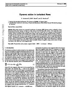
Figure 1. Time-evolution of the total stress (blue), Reynolds (green) and Maxwell (red) stresses, all normalized by mean pressure, for simulation MRI-S1 (Lx = 2 H0 , Ly = 4 H0 and Lz = 6 H0 )
(19)
Spectra and small/large-scale ratios
EK (kx , ky , z) =
0.010
where kx0 = 2π/Lx . To quantify the importance of smallscale motions relative to large-scale motions, we introduce the z-dependent ratio:
This relation is very similar to Gammie (2001) but includes vertical losses through the boundaries. Note that replenishing mass in the midplane and imposing a density threshold does not introduce any loss or gain of total energy. It can alter the internal energy budget but the changes are small and will always happen on a timescale & (Ωα)−1 . It is worth pointing out that, in the case τc = ∞ (no explicit cooling), a thermodynamic equilibrium is reached when the turbulence produces as much energy as it is able to expel vertically. Then the transport efficiency α directly depends on the wind properties and flux transport at the boundary. This itself depends on various quantities, such as the disc magnetization, the turbulent activity (related to α) but also the numerical details of the code, in particular the vertical box size (Fromang et al. 2013).
2.4.3
0.015
(18)
If turbulence is in a steady state then we expect α(t)(γ − 1)S =
Mxy/P
�Lz /2
�Z Z Fz [X] =
Hxy/P
0.020
−0.005 0
and
α = (Hxy + Mxy)/P
0.025
(20)
EK (nπH0−1 , z) , EK (pπH0−1 , z)
(23)
with n � p. At a given height, this diagnostic tells us how much kinetic energy is in long azimuthal scales (= 2H0 /n) vis-a-vis short scales (= 2H0 /p). Similarly we define EM (ky , z) and Λn,p M (z) for the magnetic field.
3
MHD SIMULATIONS WITHOUT SELF-GRAVITY (Q → ∞)
Before including self-gravity, it is necessary to understand the properties of MRI-driven turbulence in numerical models involving diabatic gas and very large horizontal domains. While there is a rich literature describing the MRI in isothermal stratified shearing boxes, only a few studies have dealt with the thermodynamic evolution of an ideal gas subject to non-adiabatic processes (Turner et al. 2003; Hirose & Turner 2011; Bodo et al. 2012; Gressel 2013; McNally et al. 2014; Hirose et al. 2014; Coleman et al. 2017). Some of these have highlighted the ability of MRI turbulence to sustain convective motions that alter the system’s turbulent transport and dynamo properties. However, none exactly correspond to our setup. In this section we perform our own pure MRI simulations that can be directly compared to our later mixed GI/MRI simulations. We stress that in this section we omit explicit cooling, so that Λ = 0 (i.e. τc → ∞), and thus the box is permitted to slowly heat up via turbulent dissipation. Note that some of this energy will be lost due to weak outflows through the box’s vertical boundaries. The effective cooling timescale of these outflows ranges between
6 roughly 150Ω−1 and 250Ω−1 .
3.1
Small boxes
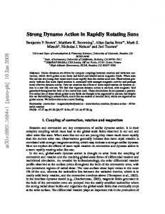
We performed a first test simulation of stratified MRI-driven turbulence, labelled MRI-S1 (see Table 1) with γ = 5/3 and no cooling (τc = ∞). This simulation has zero-net flux, no explicit diffusion, no self-gravity, and has been run in a small box of size Lx = 2 H0 , Ly = 4 H0 , Lz = 6 H0 for 1500 Ω−1 . The resolution is 26 points per H0 in x and y, and 21.3 points per H0 in the vertical direction (our standard resolution for most of the simulations in this paper). Actually this setup is similar to the stratified simulations of Simon et al. (2011) except that γ differs from 1. Figure 1 shows the time evolution of α, the ratio of total stress over pressure. The turbulent activity is sustained during the whole simulation and saturates at α = 0.0076. This value is similar to that found by Gressel (2013) but slightly smaller than those found in isothermal simulations of similar resolution per H0 : Davis et al. (2010) found α ' 0.01 while Simon et al. (2011) found α ' 0.027 with no explicit diffusion. The ratio of Maxwell stress to Reynolds stress Mxy /Hxy ' 3.32 is consistent with previous stratified MRI simulations. The space-time diagram shown in Fig. 2 (top panel) reveals that the large-scale toroidal field oscillates between positive and negative values with a period of ∼ 20 − 25 orbits. Each reversal starts in the midplane and propagates upwards/downwards into the disk atmosphere, thus generating “butterfly diagrams”. This behaviour has appears in nearly all stratified MRI simulations (Brandenburg et al. 1995; Davis et al. 2010; Simon et al. 2011; Oishi & Mac Low 2011; Gressel et al. 2015) and is classically attributed to a large-scale dynamo driven by non-axisymmetric MRI waves (Rincon et al. 2007; Lesur & Ogilvie 2008). Note that the period of each reversal in our simulations is twice longer than that typically inferred from classical isothermal simulations. Moreover, the butterfly diagram is slightly erratic: e.g. the toroidal field in the midplane sometimes conserves its polarity (as between t = 300 and t = 450 Ω−1 ). Bodo et al. (2012) and Gressel (2013) also reported a marked and analogous sensitivity of the butterfly patterns to the thermodynamics (and vertical boundary conditions), while Hirose et al. (2014) and Coleman et al. (2017) suggest that hydrodynamic mixing of magnetic fields by convective motions might weaken the field reversals. We, however, find no evidence of convection in our simulations, although the squared Brunt-Vaisala frequency N 2 occasionally takes small negative values near the midplane.
3.2
Large boxes and zonal flows
Since our aim is to capture both MRI and GI, simulations have to be run in much larger boxes than used in MRI-S1. Therefore we ran a second test MRI simulation without self-gravity, labelled MRI-L1, in a box 10 and 5 times larger in x and y respectively, but with the same resolution in both directions (26 points per H0 ). Table 1 contains lists of time-averaged quantities that
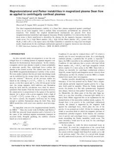
may be compared with those of MRI-S1. We found that the Reynolds and Maxwell stresses are both smaller in the larger box as compared with the small box. The magnetic energy halves, although kinetic and internal energy remain similar. The space-time diagram of Fig. 2 (centre panel) shows that the large-scale dynamo field By reverses fairly regularly every ∼ 5 − 10 orbits. However, the turbulent flow undergoes long term variability (' 50 orbits) with periods of high/moderate magnetic activity (e.g. in the early stage of the simulation between t = 200 and 450 Ω−1 and also around t = 1000 Ω−1 ) followed by periods of weaker activity (between t = 500 and 800 Ω−1 ). The polarity of the magnetic field during the latter phase can be markedly asymmetric about the midplane. To better understand the origin of these variations, we plot in Fig. 3 the density ρ and the radial field Bx in a plane z = H0 , at two different epochs, t = 300 Ω−1 (corresponding to high activity) and t = 700 Ω−1 (corresponding to low activity). In the first case (left panels), the turbulence is well-developed, homogeneous, and mainly small-scale. Magnetic bundles of size ∼ 0.2 H0 are elongated along the shear and distributed uniformly. In the second case (right panels), the turbulence is weaker and more patchy, and the flow has formed into larger scale structures. In particular, the density develops long-lived axisymmetric rings or “zonal flows”. The density contrast between each band is significant, of the order 50% of the background. Small-scale magnetic filaments are still visible but they remain confined to azimuthal bands, where the Alfv´en speed is larger. Note that at t = 1000 Ω−1 , when the magnetic activity regains its strength, the density is dominated again by small-scale structures, although faint zonal flows can still be distinguished in the background. MRI zonal flows have been reported in several MRI simulations with radial box sizes much larger than H0 (Johansen et al. 2009; Simon et al. 2012; Kunz & Lesur 2013; Bai & Stone 2014). Their provenance remains unclear and a subject of ungoing research. Usually the lengthscale of these features increases to a value near the radial box size, and it is likely that finite-domain effects rather than physical effects limit this growth. In keeping with previous results our large box (Lx = Ly = 20 H0 ) hosts at least two zonal structures. The emergence of large-scale zonal flows can have a considerable impact on the overall dynamics. First, a significant amount of angular momentum may be transported on scales � H0 (Beckwith et al. 2011; Simon et al. 2012), which breaks the assumption of locality and casts doubt on the validity of the alpha model. However, we found the opposite: large-scale zonal flows induce a drop in the total boxaveraged stress and transport. Second, zonal flows strongly influence the turbulent spectrum and small-scale structure. Figure 4 shows the 1D kinetic power spectrum EK (ky , z), averaged over kx , as a function of z and ky . In the small box, kinetic energy is spread uniformly in z over ky . In contrast, the spectrum in the large-box simulation adopts a funnel shape. More energy is found on large scales and power is depleted on small scales in the midplane region, where the zonal flows are present. This behaviour is more obvious in plots of the small/large-scale ratio Λ10,1 K (z) (right panel). An increased box size makes MRI-driven flows more laminar in the midplane. Indeed, By and the Maxwell stress −Bx By are MNRAS 000, 1–22 (2017)
7 Run
Resolution
Time (Ω−1 )
τc (Ω−1 )
Q
ET
Ec
Em
Hxy 10−4
Gxy
Mxy
MRI-S1 MRI-S2 MRI-S3-HD MRI-L1
52 × 104 × 128 64 × 128 × 128 128 × 256 × 256 5122 × 128
1500 1500 1200 1500
∞ ∞ ∞ ∞
∞ ∞ ∞ ∞
0.62 0.59 0.48 0.408
0.0029 0.0029 0.0020 0.0027
0.0096 0.0087 0.0055 0.0041
7.5 × 6.6 × 10−4 4.8 × 10⁻⁴ 3.6 × 10⁻⁴
0 0 0 0
0.00250 0.00215 0.00175 8 × 10⁻⁴
MRISG-200 MRISG-100 MRISG-20
5122 × 128 5122 × 128 5122 × 128
300 600 100
200 100 20
1.50 1.43 1.22
0.537 0.485 0.35
0.015 0.021 0.040
0.0016 0.0017 0.0045
0.0015 0.0019 0.0032
0.0013 0.0020 0.007
2.6 × 10⁻⁴ 3.5 × 10⁻⁴ 0.0015
SG-hydro SGMRI-20 SGMRI-10 SGMRI-5 SGMRI-2
5122 × 128 5122 × 128 5122 × 128 5122 × 128 5122 × 128
200 320 100 60 14
20 20 10 5 2
1.26 1.20 1.21 1.17 frag
0.412 0.362 0.363 0.33 frag
0.109 0.041 0.062 0.067 frag
0 0.0061 0.021 0.043 frag
0.0059 0.0034 0.0064 0.011 frag
0.0096 0.007 0.010 0.015 frag
0 0.0017 0.0071 0.014 frag
SGMRI-20-Rm100 SGMRI-100-Rm100 SGMRI-20-By0.1 SGMRI-20-Bz0.1
1282 × 64 1282 × 64 5122 × 128 5122 × 128
600 400 200 40
20 20 20 20
1.25 1.25 1.29 1.54
0.382 0.49 0.40 0.58
0.0259 0.014 0.042 0.113
0.272 0.14 0.014 0.368
0.0048 0.0022 0.0042 0.036
0.0025 0.0017 0.0065 0.0024
0.021 0.0064 0.011 0.167
Table 1. Simulations runs and their box and time-average turbulent quantities. The first three simulations (small box MRI without GI) have Lx = 2 H0 , Ly = 4 H0 , while the rest have Lx = Ly = 20 H0 . The third column indicates the time over which quantities have been averaged (excluding transient phases). Q is the Toomre parameter, ET , Ec and Em are respectively the internal, kinetic and magnetic energy, Hxy , Gxy and Mxy are the Reynolds, gravitational and Maxwell stresses. Note that for SGMRI-2, “frag” means fragmentation.
Run
Time (Ω−1 )
τc (Ω−1 )
τw (Ω−1 )
m ˙w
α
αth −1 = τc−1 + τw
MRI-S1 MRI-S2 MRI-S3 MRI-L1
1500 1500 1200 1500
∞ ∞ ∞ ∞
148.7 x x 248.5
2.9 × 10−3 x x 1.76 × 10−3
0.0076 0.0075 0.0068 0.0043
0.0067 x x 0.0040
MRISG-100
600
100
233.7
7.09 × 10⁻⁴
0.0133
0.0142
SG-ref SGMRI-20 SGMRI-10
200 320 0
20 20 10
150.0 110.6 85.4
5.0 × 10⁻⁴ 7.46 × 10⁻⁴ 9.3 × 10⁻⁴
0.056 0.051 0.10
0.057 0.059 0.11
Table 2. Wind and transport quantities of some simulations shown in Table 1. τw is the timescale at which total energy is lost through winds (defined in Eq. 18), mw is the time-averaged mass loss rate through the vertical boundaries, α is the transport efficiency and αth is the theoretical efficiency given by the total averaged energy equation (19). Note α is defined as the standard ratio of stress over pressure without the factor qγ and thus differs from Gammie (2001) and Riols et al. (2017).
smaller in the midplane than in the corona. One way to explain this result is that zonal flows pump energy from small scales to large scales (Simon et al. 2012). A more worrying possibility could be that these zonal flows produce regions of very low magnetization, in which the MRI grows only on scales shorter than the grid size and is hence misrepresented in the simulation. This prospect is discussed in further detail in the next subsection.
In conclusion, the emergence of zonal flows in large boxes, residing preferentially in the midplane regions, seems to induce a drop in turbulent activity and the formation of “deserts” in which small-scale turbulence is absent. MNRAS 000, 1–22 (2017)
3.3
The resolution problem
If the dependence of the MRI on box size is an issue, then what of its dependence on resolution? Is MRI turbulence adequately resolved with 26 points per H0 in x and y and 21 points in z? The question of the convergence of MRI with resolution in stratified shearing box simulations has been debated for a number of years. Early simulations by Shi et al. (2010); Davis et al. (2010); Simon et al. (2011) suggested convergence of α with resolution. However, the most recent and numerically intensive simulations by Bodo et al. (2014) and Ryan et al. (2017), indicate the contrary: convergence is still not obtained even up to 256 points per
8 2
MRI-S1 (small box)
1 0 −1 −2
−3 0
200
400
600
3
800
1000
Time /Ω−1
1200
1400
MRI-L1 (large box)
2 1 0 −1 −2 −3 3
(large box)
2
200
400
MRI-L1
600
800
MRIGI-100
z
1 0 −1 −2 −3
700
800
900
1000
Time /Ω−1
1000 1100 1200 1300 1400
0.08 0.06 0.04 0.02 0.00 −0.02 −0.04 −0.06 −0.08
1200 SGMRI-20
1400 SGMRI -10
0.24 0.18 0.12 0.06 0.00 −0.06 −0.12 −0.18 −0.24 0.08 0.06 0.04 0.02 0.00 −0.02 −0.04 −0.06 −0.08 0.2 0.1 0.0
By
3
−0.1 0
50 100 150 200 250 300 350
−0.2
Time /Ω−1 Time /Ω−1 Figure 2. Space-time diagrams of the horizontally averaged By . Top panel: the small-box pure MRI simulation MRI-S1. Centre panel: the large-box pure MRI simulation MRI-L1. Bottom left: simulation MRI-L1 and the MHD gravito-turbulent simulation with τc = 100 Ω−1 started from it (MRISG-100). The vertical dashed line indicates the transition from one to the other (at t = t2 ' 900 Ω−1 ) . Bottom right: MRI and self-gravitating simulations with τc = 20Ω−1 and τc = 10Ω−1 , with the dashed vertical line again indicating the transition from the former to the latter. 1
H0 (with α ∼ N − 3 ). As no convergence test has been performed for MRI in the diabatic case, we examined the properties of the saturated state at larger resolution. For computational reasons, we restricted our study to the case of a small box. Starting from the same initial condition as MRI-S1, we performed two simulations, one with resolution of 32 points per H0 in x and y but the same resolution in z (MRI-S2), the second with double resolution in each direction (MRI-S3, 64 points per H0 in x and y and 43 points per H0 in z). Each simulation was run for more than 1000 Ω−1 to obtain meaningful statistical averages. Tables 1 and 2 show that all turbulent average properties, and in particular α, slightly decrease when resolution is increased although no real trend can be inferred from our runs. According to Ryan et al. (2017), a significant change in average quantities would require us to go beyond 64 points per H0 (which means at least 2000 × 2000 × 512 in the large boxes we intend to use). The main point we wish to make is that numerical convergence with resolution cannot be achieved with our resources and is unlikely to exist in any case. Though the MRI in our simulations may be formally unresolved, its interaction with GI may still be adequately
described. To explore this we next consider simulations with standard resolution (26 points per H0 ) and compare the characteristic MRI wavelength (for which the MRI growth rate is maximum) with the grid size. The ratio between these two lengthscales, called the quality factor, is approximately (Sano et al. 2004): 2πvAi (z) (24) Ω∆xi √ where vAi = Bi / ρ denotes the Alfv´en speed in the direction i = (x, y, z). This number is obviously rather crude but gives a feeling for how well the largest MRI modes are resolved. Figure 5 shows the vertical profiles of Qy and Qz , averaged in time over 200 orbits, for the small and large box simulations. In the midplane, Qy & 20 for both simulations, taking larger value in the upper layers, which means that the non-axisymmetric MRI modes, supported by the toroidal field, might be adequately resolved in both cases. However, we note that Qy drops by a factor 2 compared to the small box run, in particular in the midplane. This is due to the zonal flows discussed in Section 3.2. In fact, the situation is worse than suggested by Fig. 5 because the quality factors shown are horizontally averaged. In fact, the zonal flows produce weakly magnetised bands in x in which Qi (z) =
MNRAS 000, 1–22 (2017)
9 10
10
0.36
0.36
0.30
0.28
0
ρ
0.27
0.24 −5 −10 −10 10
−5
0
5
10
0.24
−5
0.20 0.16
0.21
−10 −10 10
−5
0
5
10
0.08
0.10 5
0.05 0.00
0
0.04
0
Bx
y
5
0.00
−0.05 −5 −10 −10
−0.10 −5
0 x
5
10
0.18
−0.15
Bx
0
0.33
5
0.32 ρ
y
5
−0.04
−5
−0.08
−10 −10
−5
0 x
5
10
Figure 3. Snapshots of ρ (top) and Bx (bottom) in the large-box pure MRI simulation MRI-L1 at z = H0 at two different times. The left panels are for t = 300 Ω−1 while the right panels are for t = 700 Ω−1 (when zonal structures are most pronounced).
locally Qy ' 1 − 2, very low values indeed. In these weakly magnetised regions, one would need to double or quadruple the resolution to resolve the most unstable MRI modes, although it is not guaranteed even then that these structures would maintain the same level of magnetization when the resolution is increased; the magnetisation might fall with increasing resolution (Ryan et al. 2017). MRI modes supported by the vertical field are even worse and are only marginally resolved on the average, especially in the midplane where Qz ' 2 or Qz ' 5 respectively for Lx = 20 and Lx = 2. That said, the issue of vertical resolution is probably of less importance as Bz fluctuates rapidly and is mainly small scale, and thus is unlikely to support a coherent MRI mode (Simon et al. 2011). In conclusion, our standard resolution (26 and 22 points per H0 in the horizontal and vertical direction respectively) is unconverged, a problem that we must make explicit at this point. Although a resolution of 64 points per H0 does not seem to drastically change the average saturated state, the very small-scale MRI (≪ H0 ) is probably misrepresented. In particular, the generation of large-scale zonal flows, combined with a lack of resolution, weakens MRI activity in the midplane. As suggested by Ryan et al. (2017), the worst case scenario is that magnetisation slowly decreases forever with resolution. This would cast serious doubt on the MRI viability in zero-net-flux configuration without explicit diffusion. While we acknowledge these problems, we do believe MNRAS 000, 1–22 (2017)
that out setup is probably sufficient to capture the most unstable modes on intermediate scale, as well as the main nonlinear properties of the MRI dynamo. Most importantly, we can still learn a great deal from the competition of gravitoturbulence and the zero-net-flux MRI, even if the latter suffers from the problems described above.
4
MHD SIMULATIONS WITH SELF-GRAVITY
We are now in a position to analyse the interaction between GI and the MRI, and more generally between 3D gravitoturbulence and zero-net-flux magnetic fields. Our first set of runs examines long cooling times ≥ 100 Ω−1 for which GI and non-axisymmetric MRI are expected to be of similar intensity (see Section 4.1). The second set corresponds to an intermediate cooling time τc = 20 Ω−1 . We also compare states initialized from pure MRI turbulence to those initialized from pure hydrodynamic gravitoturbulence, so as to rule out any dependence on the initial condition. Our third set of simulations explores the low cooling time regime where GI is especially strong and fragmentation can occur. Lastly, we present simulations with an imposed magnetic field. 4.1
A matter of cooling times
Unlike the MRI runs of Section 3, we introduce a cooling law that favours “gravito-MRI” states. The cooling time τc turns out to be the key control parameter here: small τc '
10 3
be of similar magnitude Λ10,1 K (z) (large box)
2 10−3
0
z
τc '
Λ10,1 K (z) (small box)
1
−2 −33 2 1 z
0 −1 −3
−50
0 kyH0
10−4
50
1 1 + = q(γ − 1)(αGI + αMRI ). τc τw −2
−1
0 z
1
2
Figure 4. Left: colourmaps showing the time-averaged 1D kinetic power spectrum EK (ky , z) as a function of altitude z, for the small box (top) and large box (bottom) runs. On right, small to −1 large scale ratios Λ10,1 and K (z) between the PSD at ky = 10πH0 −1 ky = πH0 (green curve for small box and blue curve for large box).
55 50 45
10 Qz
Qy
35 30 20
2
15 −3 −2 −1
0 z
1
2
3
0 −3 −2 −1
0 z
1
2
3
Figure 5. Quality factors in the y (left) and z direction (right). Blue/plain curves are computed from the small box MRI simulation (MRI-S1) while green/dashed curves are from the large box MRI simulation (MRI-L1). Both simulations have a resolution of 26 points per disc scale height in horizontal directions (∆x = 0.039) and 22 points per H0 in the vertical direction (∆z = 0.046)
Ω−1 produces vigorous GI turbulence, or fragmentation in the extreme case. In the opposite limit, inefficient cooling τc � 100 Ω−1 weakens gravito-turbulent activity and thus sets the scene for MRI to dominate. As a first step, we study the case for which MRI and GI have comparable strength. We consider the two instabilities separately and arrange for a situation where the angular momentum transport associated with each are roughly equal: αMRI ' αGI .
1 ' 115 Ω−1 2qΩ(γ − 1)αMRI
(28)
Regime of inefficient cooling (τc ≥ 100 Ω−1 )
We begin by examining the regime of long cooling times in which the MRI and GI are roughly comparable. We treat two cases τc = 100Ω−1 and τc = 200Ω−1 .
6 4
τc '
4.2
8
25
One needs to estimate τw . One possibility is that αMRI = 1/τw which means that the disc winds are not affected by GI, and therefore the estimate given by Eq. (26) remains valid. The other possibility is that the wind becomes negligible when GI and MRI coexist; in that case we find that
Lx = 2 Lx = 20
12
40
(27)
In summary the critical cooling time at which the MRI and GI are equally strong is ∼ 100Ω−1 . For cooling times less than this critical value, GI should dominate.
14
Lx = 2 Lx = 20
(26)
This relation, however, is inaccurate when the two instabilities are both operating, and excludes wind cooling. Let us assume a hypothetical ideal case where each instability does not affect the other, and thus both contribute to the transport and disc heating additively. The relation given by Eq. (19), based on energy conservation, applies now to the full system {GI+MRI} which has two sources of heat. If we denote by τw the timescale of energy loss through winds, the energy balance is given by
−1
−2
1 ' 230 Ω−1 . qΩ(γ − 1)αMRI
(25)
The MRI transport efficiency is given in Table 1 (αMRI ' 0.0043) while GI efficiency is known to be inversely proportional to the cooling time, following Gammie (2001). This gives a first estimate for τc that allows both instabilities to
4.2.1
Initial state and simulation timeline
Our first runs start from a fully developed MRI turbulent state with Q → ∞ taken from the large-box simulation MRI-L1 at t1 = 750 Ω−1 . Initially we keep τc = ∞ and do not introduce full self-gravity straight away, but only its mean and static vertical component. The reason is to check that MRI can be sustained in a disc compressed by its own gravity, neglecting the action of GI fluctuations and spiral waves. To avoid sharp changes to the disc structure and thermodynamics, the Toomre parameter Q is progressively decreased and set to a value around 1.6 (see top panel of Fig. 6 from t1 = 750 Ω−1 ). This is done by taking G ∝ 1 − e−(t−t1 )/τG with τG ' 50 Ω−1 . By t ' 800 Ω−1 , the disc has converged upon a new turbulent state whose averaged properties are plotted in light/ cyan in Fig. 6. Note that only 20 orbits (between 750 and 900 Ω−1 ) are represented here to avoid plot overloading, but we actually obtained this state for longer time. Finally at t = 900 Ω−1 , full self-gravity (including its fluctuating part) and cooling are introduced. The evolution of corresponding averaged quantities are plotted in green in Fig. 6 for the case τc = 100 Ω−1 . They can be directly compared to those obtained in the pure MRI simulation (blue curves, MRI-L1). The new state with self-gravity is labelled “MRISG-100”. MNRAS 000, 1–22 (2017)
Internal U
Q
11 2.0 1.8 1.6 1.4 1.2 1.0 0
Toomre parameter
200
400
600
200
400
600
t1 800
t2
Energy
1000
1200
1400
1600
1000
1200
1400
1600
1000
1200
1400
1600
0.6 0.4
Magnetic Em
Kinetic Ec
10−1 10−2 10−3 10−2
10−3 0
800
0.015 0.005 −0.005 −0.015 0.008 0.006 0.004 0.002 0.000
Magnetic Mxy
Grav. Gxy
Reynolds Hxy
Stress
0.0020 0.0015 0.0010 0.0005 0.0000 0
200
400
600
800 Time in Ω−1
Figure 6. Time-evolution of various quantities, averaged over a box of size Lx = 20, Ly = 20 and Lz = 6 H0 . From top to bottom, Toomre parameter Q, box average internal, kinetic and magnetic energy, box average Reynolds, gravitational and Mawxell stress. The blue/dashed curves corresponds to the MRI run without self-gravity (MRI-L1) while the green/plain curves represent the run with selfgravity and τc = 100 Ω−1 (MRISG-100). The cyan/light curve represents the transition phase in which only the mean vertical component of self-gravity is incorporated (no GI fluctuations). All simulations have a resolution of 512 × 512 × 128.
4.2.2
MRI and its interaction with GI
Fig. 6 shows that during the transition phase (between t1 and t2 , cyan/light curves), when only the mean vertical component of self-gravity is considered, the internal energy slightly increases from 0.4 to 0.6 due to the disc compression, but the other quantities do not change all that much. The turbulent stresses, normalized to the pressure, are comparable to those obtained in the limit Q → ∞. The magnetic field reverses 3-4 times and we checked that the butterfly diagram is not affected; a fraction of the toroidal magnetic flux is transported upward by buoyancy, while the dynamo cycle period is similar to the case Q → ∞. At t2 = 900 Ω−1 , as full self-gravity is introduced, the MNRAS 000, 1–22 (2017)
turbulent state changes radically. Figure 6 (green curves) shows that for τc = 100 Ω−1 , the mean Toomre parameter and internal energy drop under the effect of the cooling but seem to both converge to a steady value (in particular Q ∼ 1.4) as soon as spiral shocks develop. Kinetic energy Ec and Reynolds stress Hxy increase by a factor 10 while magnetic energy and Maxwell stress slightly decrease but remain of the same order of magnitude (Em decreases actually by a factor ' 2 on average between t = 1000 and t = 1500 Ω−1 ). In addition to the Maxwell and Reynolds stresses, the flow is subject to a strong gravitational stress Gxy ' Hxy . Note that, unlike magnetic quantities, both hydrodynamical and gravitational turbulent components are highly fluctuating.
12 τc = 100 Ω−1
τc = 20 Ω−1
10
5
0
0
0
−10 −10
x
5
−5
−5
−5
0
5
−5
−10 10 −10
5
5
0
0
−5 −10 −10
0
−5 0.15
10
y
y
0.08 0.16 0.24 0.32 0.40 0.48 0.56 ρ 10
τc = 20 Ω−1 (hydro)
10
5
y
y
10
0.30
0.45 ρ
−10 10 −10
5 0.60
0.75
0
−5 0.2
0.4
0.6
ρ
5 0.8
10
1.0
1.2
−5
−5
0
5
−10 10 −10
−0.06 −0.04 −0.02 0.00 0.02 0.04 0.06 Bx
−5
0
−0.12 −0.06 0.00 Bx
5 0.06
10 0.12
rho 7 6
4
2
0 Figure 7. Top: snapshots of ρ and Bx at z = H0 , taken from different simulations. From left to right, magnetized GI turbulent states with τc = 100 Ω−1 (MRISG-100), τc = 20 Ω−1 (MRISG-20) and a pure hydrodynamic GI state (SG-hydro) with τc = 20 Ω−1 . Bottom: 3D view of a plasmoid embedded in a magnetic island from a simulation with τc = 5Ω−1 . The colours indicate the density and white lines represent some horizontal magnetic field lines. All simulation have Lx = Ly = 20 H0 and a resolution of 512 × 512 × 128. MNRAS 000, 1–22 (2017)
13
r.m.s velocity fluctuations
1.4
pure MRI
1.2 1.0 0.8 0.6 0.4
q
u2x q Azimuthal u2y q Vertical u2z Radial
cs
0.2
0.0 −3 −2 −1 0 z 0.12 r.m.s magnetic fluctuations
1.6
1
2
0.10 0.08 0.06 0.04 0.02 0.00 −3 −2 −1 0 z
1
2
τc = 100 Ω−1
τc = 20 Ω−1
1.6
1.4
1.4
1.4
1.2
1.2
1.2
1.0
1.0
1.0
0.8
0.8
0.8
0.6
0.6
0.6
0.4
0.4
0.4
0.2
0.2
0.2
0.0 −3 −2 −1 0 z 0.09 0.08 0.07 0.06 0.05 0.04 0.03 0.02 0.01 0.00 3 −3 −2 −1 0 z 3
1.6
1
2
3
0.0 −3 −2 −1 0 z 0.30
1
2
0.25
3
0.0 −3 −2 −1 0 z 0.20 0.15
0.20
0.10
0.15 0.05
0.10
2
3
0.00 −3 −2 −1 0 z
1
2
3
q
B2x q Azimuthal B2y q Vertical B2z Radial
0.00
0.05 1
τc = 20 Ω−1 (hydro)
1
2
−0.05 3 −3 −2 −1 0 z
1
2
3
Figure 8. Vertical profiles of turbulent r.m.s velocity (top) and magnetic (bottom) components, time averaged over four different simulations. From left to right, the pure MRI state without self-gravity (MRI-L1), the combined MRI+GI state with τc = 100 Ω−1 (MRISG-100), the case of intermediate τc = 20 Ω−1 (SGMRI-20) and the pure hydrodynamic state (SG-hydro) with τc = 20 Ω−1 .
The important result here is that Em � Ec and Mxy � Gxy . The gravitational stress, which is directly related to GI turbulence, is on average 6 times larger than the Maxwell stress, which we associate at this point with the MRI. The transport is then mainly driven by the gravitational instability. This might be a surprise because our cooling time had been explicitly chosen in order to satisfy Gxy ' Mxy (see Section 4.1). Note that in making this choice, we assumed that both instabilities do not interact with each other, evidently an assumption that is incorrect. Moreover, as shown in Table 2, winds carry a non-negligible amount of energy (mainly internal energy). According to 4.1, one may argue that a cooling time of 100 Ω−1 is then still too low to ensure Gxy ' Mxy . However, we checked that for a cooling time τc = 200 Ω−1 , the saturated state is in fact comparable (see Table 1). It is unproductive to go to longer τc : as we approach the limit τw ≈ τc , the wind will cool the disc at a rate greater than the explicit Newtonian cooling.
Figure 7 (top left panels) shows a snapshot of the density ρ and radial magnetic field Bx at z = H0 for τc = 100 Ω−1 . Surprisingly, the density field is not dominated by large-scale spiral waves but rather by thin wispy filaments, elongated in the radial direction and perturbed by small-scale non-axisymmetric wobbles. We show in Section 5.2 that these small-scale features are probably manifestations of a “sluggish” MRI that persists in the gravito-turbulent background. The manifestation of large-scale zonal flows in the density seem to have MNRAS 000, 1–22 (2017)
disappeared. But the bottom panel shows that the magnetic field concentrates into small-scale bundles (of size � H0 ) localized preferentially along thin filaments or axisymmetric rings (parallel to the x axis). Although is it difficult to determine the origin (MRI or not) of these structures, they are reminiscent of those found in large box MRI. Finally, we examined the evolution of the mean toroidal magnetic field By . The space-time diagram of Fig. 2 (bottom left) shows that once self-gravity is included (at t = t2 = 900 Ω−1 ), the field still reverses quasi-periodically, suggesting the existence of a large-scale dynamo. However, the period of the reversal is longer than in the pure MRI case (50 orbits instead of 20) and the reversals are even more irregular. In addition, the butterfly patterns disappear and the magnetic flux remains confined near the midplane. The fact that magnetic flux cannot easily rise is possibly due to the strong stratification in runs with self-gravity. Indeed, we checked that the Brunt-Vaisala frequency increases rapidly with z in comparison to the case without GI. According to the Newcomb criterion, magnetic buoyancy should be impeded. This behaviour, however, may not be characteristic of realistic disc models with more sophisticated cooling treatments. The confinement of the magnetic fluctuations can be also observed in Fig. 8 (first and second bottom panels), which compares the time-integrated r.m.s. magnetic components of MRI-L1 (pure MRI without self-gravity) with that of MRISG-100 (with self-gravity). Although the maximum amplitude of each component and the ratio By /Bx are very
14 similar, their distribution along z differs considerably. In the pure MRI case, Bx and By are distributed over a wide range of altitude and are maximum at z ' 1 − 2H0 . In the selfgravitating case, they preferentially peak in the midplane. Note also that velocity components are much stronger, in particular vx and vz in the corona (top panels of Fig. 8).
4.3 4.3.1
Regime of moderate cooling (τc = 20 Ω−1 ) Starting from an MRI-turbulent state with Q → ∞
We performed a simulation, labelled MRISG-20, using the same initialization as in Section 4.2.1, i.e. starting with an MRI-turbulent state. The difference is that τc = 20 Ω−1 , instead of 100 or 200. Table 1 shows that in this intermediate regime, the activity is 2-3 times greater than for τc = 100 Ω−1 but the ratio between the Maxwell and gravitational stresses and Em /Ec remains relatively small. There is also a substantial drop in Q and internal energy. Figure 7 shows that large scale spiral waves, characteristic of GI, become prominent, as opposed to the case τc = 100 Ω−1 . The magnetic field forms small-scale bundles with sizes comparable to those found at larger cooling times. Magnetic structures either follow the spiral waves shape or regroup into radial axisymmetric bands.
4.3.2
Starting from hydrodynamic gravito-turbulence
One interesting question is the dependence of our results on initial conditions. Instead of starting from an MRI-turbulent state, one could imagine starting from a hydrodynamic GI turbulent state, in which a seed magnetic field is introduced. Will the final state look like the one described in 4.3.1, or will it be different and thus indicative of hysteresis? To answer this, we prepared a 3D hydrodynamic gravito-turbulent state (without magnetic field) with τc = 20 Ω−1 . This state is obtained from the simulation “SG-hydro”, already described in Riols et al. (2017). At t = 40 Ω−1 , we introduced a zeronet-flux toroidal seed field, with sinusoidal shape in z and initial amplitude By0 = 10−3 . Figure 9 shows the evolution of various averaged quantities computed from the pure hydrodynamic simulation (blue curve) and the new magnetic state that it initiates (green curves, labelled SGMRI-20). An immediate and important result is the quasi-exponential amplification of the seed magnetic field by the pre-existing turbulent flow. The amplification lasts for 200 Ω−1 and the dynamo field then saturates at Em ≈ 0.006, which is 6000 times larger than its initial value, but still smaller than the average kinetic energy Ec ≈ 0.04. Second, we found that the final state is very similar to the one computed in 4.3.1, suggesting that it is independent of the initial condition. Note finally that the confinement of the magnetic field is even stronger than for τc = 100 Ω−1 (see Fig. 2 and Fig. 8)
4.3.3
quantities, since Q, ET , and Gxy are much the same. However, there is a non-negligible drop in kinetic energy and Reynolds stress (roughly a factor 2), indicating the propensity of the Lorentz force to impede GI motions. Figure 8 (third and fourth panels) shows that the r.m.s velocity fluctuations are smaller than in the hydrodynamical run SGhydro. The mean magnetic pressure is far too weak, compared to the thermal pressure, to compete with self-gravity and interfere with the linear response of the GI modes. It is more likely that the local gradients of magnetic fields nonlinearly affect the dynamics of the turbulent waves through magnetic tension. To carry out a more in-depth investigation, we analysed the spectra and in particular the small-scale activity. Recently, the hydrodynamic GI was found to be subject to a small-scale parametric instability, probably due to the resonance between inertial waves and a large-scale epicyclic mode (Riols et al. 2017). The small-scale structures instigated by this instability are visible in the density plot on the top right panel of Fig. 7. They take the form of small ribbon-like fluctuations that disturb the spiral wave fronts. How does this instability behave in presence of a tiny but non-negligible magnetic field? Visually, Fig. 7 (top, central panel) shows that structures of scale . H0 are still present, in particular in the left part, but they are less pronounced. In particular, in the right part where the magnetic field is stronger, GI spiral waves are almost entirely free of the small-scale parasitic turbulence, suggesting that magnetic fields suppress the parametric instability. This result can be checked quantitatively and statistically by plotting the time-averaged spectrum EK (ky , z) of both simulations, SG-hydro and SGMRI-20. The result, shown in Fig. 11, clearly indicates that in the MHD case less kinetic energy is found on small scales (large ky ). Additionally, we found that: 10,1 Λ10,1 K (H0 )MHD ' 0.17 ΛK (H0 )hydro ,
(29)
proving that the ratio of large-to-small scales differ by about an order of magnitude in the two simulations. The small-scale parametric modes are thought to be excited by a large scale axisymmetric oscillation with kx = kx0 = 2π/Lx (Riols et al. 2017). In hydrodynamic simulations this mode possesses a large amplitude ' 0.5 cs and undergoes regular oscillations at a frequency close to Ω (Riols et al. 2017). We now check what happens to this mode when a magnetic field is included. Fig. 10 shows the time-evolution of its kinetic energy in the MHD simulation (blue curve) and in the hydrodynamic simulation (cyan/light curve). Strikingly magnetic fields damp and ultimately kill the large-scale axisymmetric oscillation kx = kx0 . Figure 10 also shows that the harmonic modes (in particular kx = 2kx0 and kx = 3kx0 ) remain weak and are unimportant. By projecting the forces onto the mode kx = kx0 , we found that magnetic tension and pressure have no direct effect on it. Instead, the field is degrading the nonlinear couplings that feed the axisymmetric mode.
Comparison with the pure hydrodynamic GI state
We next compare the magnetized state with the pure hydrodynamic GI state, computed for the same τc = 20 Ω−1 (green vs blue curves in Fig. 9). Magnetic fields do not seem to have a substantial effect on the thermodynamics and gravitational
4.4
Regime of efficient cooling and fragmentation (τc ≤ 10Ω−1 )
The last regime investigated is the one of short cooling times τc ≤ 10 Ω−1 . Three cases were considered: Ωτc = 10, 5, MNRAS 000, 1–22 (2017)
Q
15 2.0 1.8 1.6 1.4 1.2 1.0 0
Toomre parameter
50
100
150
200
250
300
350
50
100
150
200
250
300
350
150 200 Time in Ω−1
250
300
350
Energy
Magnetic Em
Kinetic Ec
Internal U
0.6 0.5 0.4 0.3
10−1
10−2 10−2 10−3
Magnetic Mxy
Grav. Gxy
Reynolds Hxy
10−4 0
Stress
0.09 0.06 0.03 0.00 −0.03 −0.06 0.025 0.020 0.015 0.010 0.005 0.003 0.002 0.001 0.000 0
50
100
Figure 9. Time-evolution of various quantities, averaged over a box whose size is Lx = 20, Ly = 20 and Lz = 6 H0 . From top to bottom, density-weighted average Toomre parameter Q, box average internal, kinetic and magnetic energy, box average Reynolds, gravitational and Maxwell stress. The blue/dashed curves corresponds to the pure 3D hydrodynamical gravito-turbulent state (SG-hydro) while the green/plain curve represents the same state with magnetic field (SGMRI-20), initialized from the hydrodynamic simulation. Simulations have a resolution of 512 × 512 × 128 and τc = 20 Ω−1 .
and 2. Each simulation was initialized from the neighbour state with longer τc . In the first two cases, τc = 10 Ω−1 and τc = 5 Ω−1 , we simulated gravito-turbulent states for ∼ 100 Ω−1 � τc . Table 1 shows the averaged quantities corresponding to these states. To compare with simulations of longer τc , we plot in Fig. 12 the mean kinetic and magnetic energies as well as the different stresses as a function of cooling time τc . This figure displays one of the most important results of our paper. As τc decreases, and the disc enters the efficient cooling regime, magnetic and kinetic energy tend to equipartition. In addition, the Maxwell stress grows larger than the Reynolds stress and attains values comparable to the gravitational stress. In this regime, we found that a strong primarily toroidal field dominates, its morphology similar MNRAS 000, 1–22 (2017)
to the large scale spiral wakes. This is certainly suggestive that a powerful dynamo is supported by the spiral waves (see Section 5 for further discussion). We checked that the flux is again confined near the midplane, between −H0 and H0 , although the confinement appears no stronger than for τc = 20 Ω−1 . Figure 11 (right column) shows the magnetic spectrum for different τc . In addition to the strong large-scale field there is evidence here of energy on shorter scales when τc tends to small values. These small-scale structures are much more developed than in the pure MRI case, and may be telling us that reconnection is an important ingredient sustaining this state. Indeed, in the low τc regime, the flows generate transient plasmoids embedded within magnetic pressure rings (or magnetic islands) and which we associate with
16
z
0.15
0.10
3
2 MRI-L1
2
1
1
0
−1
−3 3
−3 3
−2
−1 2 τc = 100 Ω
200
250
−1
300
−2
−2
−3 3
2 τc = 20 Ω
To study the dependence of our results on magnetic field geometry, we performed two simulations, one with a strong initial imposed toroidal field, the other with a net vertical field. In both cases τc = 20Ω−1 . In the first run, labelled SGMRI-20-By0.1, the net toroidal flux in the box, initially hBy i = 0.1, is free to evolve during the simulation. Our aim is to make a comparison with 2D simulations (Riols & Latter 2016), in which a mean toroidal field was imposed. Table 1 shows that the magnetic perturbations reach almost equipartition, however the average temperature and Q in the box fail to rise significantly. In contrast, Q was found to be 3 times larger than its hydro-
2 1
0 −1 −2
−2 0
50
1
−3 3 2 1
0
z
z
0 −1
−50 −1 2 τc = 10 Ω
Effect of a strong imposed By or a net Bz
−3 3
−1
1
−3 3
0
−1
−1
−3 3
−3
−2
−2
2 hydro
−50
0 kyH0
50
1 z
reconnection sheets. See the bottom panel of Fig. 7 for a 3D rendering of an example plasmoid. The plasmoids resemble those appearing in Riols & Latter (2016) but are somewhat more marginal and survive for only a few Ω−1 . Finally, for τc = 2 Ω−1 the magnetic field becomes even more intense during the first 15 Ω−1 but the disc fragments into several bound objects with densities exceeding 1000 times the background density. The time step becomes of order 10−6 and makes the study of this state impossible. In conclusion, for cooling times τc . 10 Ω−1 , a powerful dynamo mechanism amplifies a magnetic field to equipartition levels much stronger than what the MRI is capable of. The field displays both strong large-scale toroidal features and small-scale non-axisymmetric structure. Fragmentation occurs for cooling times very similar to those obtained in 3D hydrodynamic GI (Shi & Chiang 2014; Riols et al. 2017). Regarding this last point, we warn the reader that the fragmentation criterion probably depends on numerical resolution. Transient clumps are not much larger than the grid size and so we expect numerical diffusivity to weaken magnetic tension on these scales. Magnetic tension might otherwise facilitate gravitational collapse because of its breaking of angular momentum conservation.
0 −1
z
150 Time in Ω−1
1
0
z
z 100
Figure 10. Time-evolution of the fundamental axisymmetric mode kx = kx0 for the MHD (SGMRI-20, blue curve) and for the hydrodynamic simulation (SG-hydro, cyan curve). We superimposed in green and red the harmonic modes kx = 2kx0 and kx = 3kx0 for SGMRI-20. Note that for SG-hydro, the axisymmetric mode continues until t = 200 Ω−1 (not show here due to a crude sampling)
4.5
2
1
50
0
−1 −2
0.05
0.00 0
3
z
kx = kx0 = 2π/Lx kx = 2kx0 kx = 3kx0
z
Kinetic energy of axisymmetric modes
0.20
0
−6 −5 −4 −3 −2 −1 0
−1 −2 −3
−50
0 kyH0
50
−9
−6
−3
1
2 0
Figure 11. 1D kinetic EK (ky , z) (left) and magnetic EM (ky , z) (right) power spectrum as a function of ky and altitude z. From top to bottom: 1: pure MRI (MRI-L1), 2: GI with MHD and τc = 100Ω−1 (MRISG-100), 3: GI with MHD and τc = 20 Ω−1 (SGMRI-20), 4: GI with MHD and τc = 10 Ω−1 (SGMRI-20) and 5: hydrodynamical GI (SG-hydro), τc = 20 Ω−1 .
dynamic value in 2D. The main reason for this difference is that in 3D internal energy is released via vertical outflows, and this always prevents the disc from heating up inordinately. It is however not excluded that this result depends on the vertical extent of the box. Reconnection sheets are also less active than in 2D and plasmoids are only marginally produced. A “hotter” and more active state could possibly emerge with a larger initial toroidal flux. In the second run, labelled SGMRI-20-Bz0.1, the net vertical flux hBz i = 0.1 is conserved during the simulation. This corresponds to an initial midplane plasma β = 2Σ0 H0 c2s0 /(γBz2 ) ' 225. A strong magnetic field builds up in a short period of time ' 10 Ω−1 . The final state consists of a magnetically-dominated disc with Em & Ec and Mxy � Gxy . The gravitational stress is substantially smaller than in the zero-net-flux case. The transport efficiency is very high (α ' 0.54) and reminiscent of the MRI state obMNRAS 000, 1–22 (2017)
17 0.8 ×10
10−1
Ec Em
−4
IxI
0.6
IxC
Cx Ax
0.4
Energy
0.2 0.0
10−2
−0.2 −0.4
10
3.0 ×10
10−3 0 10
101
τc
102
103
10−2
20 25 Time in Ω−1
30
35
40
Iy Cy Ay Ωy
2.5 2.0 1.5
Hxy Mxy Gxy
15
−4
1.0 0.5
Stress
0.0 −0.5 5
10−3
10−4 0 10
101
τc
102
103
Figure 12. Top: time and box-averaged kinetic and magnetic energy as functions of cooling time τc . Bottom: time and boxaveraged Reynolds, Maxwell and gravitational stress as functions of cooling time τc . The diamond markers on the right margin show these quantities for the pure MRI case.
tained by Salvesen et al. (2016) in the limit of small beta plasma and Q → ∞. To sustain such states thermodynamically, the outflows need to be quite powerful, so that τw � τc . By checking the density structures, we found that spiral GI waves are completely dominated by the MHD dynamics; unlike the zero-net flux case, the MRI seems to be strong enough to inhibit the GI. This result is nevertheless very preliminary. A more detailed investigation, spanning different hBz i will be presented in the future. The main point to take away is that the dominance of GI over MRI, witnessed in Sections 4.3 and 4.4, is not inevitable and that there exists at least one regime where the reverse situation holds.
5
FROM MRI TO SPIRAL WAVE DYNAMOS
The aim of this section is to characterise in more detail the dynamo process responsible for the large and small scale magnetic field in 3D gravito-turbulence. The results of Section 4.3.3 indicate clearly that the parametric instability is suppressed by a magnetic field, at least in cases τc ≤ 20 Ω−1 , MNRAS 000, 1–22 (2017)
10
15
20
25 30 Time in Ω−1
35
40
45
Figure 13. Evolution of the magnetic energy budget for Bx (top) and By (bottom) during the magnetic growth phase in SGMRI20 (τc = 20Ω−1 ). Each curve corresponds to a term in Eq. (30), averaged in space between z = −1.5H0 and z = 1.5H0 . Note that numerical dissipation of magnetic energy contributes to the budget (negatively), but is not represented here.
and thus we exclude a dynamo supported by helical inertial waves in what follows. In Section 4.2.2, we showed that the MRI is partially impeded by the GI motions at τc ∼ 100Ω−1 , and probably eliminated at shorter τc (Sections 4.3 and 4.4). It is imperative then to understand at lower τc whether magnetic activity is exclusively sustained by GI motions or if the MRI, though weak, remains important. If the MRI is negligible in that regime, then we must also reveal when and how the transition between the MRI and spiral wave dynamos takes place. 5.1
Magnetic energy budget and Helmholtz decomposition
To aid our understanding of the magnetic field generation we introduce certain diagnostics derived from the magnetic energy budget. The evolution of the box averaged magnetic energy for each component Bi , where i = x, y, z, is: 1 ∂hBi2 i = Ii + Ai + Ci + Di + Ωi 2 ∂t where
(30)
∂ui 1 ∂Bi2 Ai = − uj Ci = −Bi2 (∇ · u) (31) j ∂x 2 ∂xj and Ωi = −SBx By δiy . The summation on the index j is implicit in (31). The first term Ii is the induction or “stretching” term, the second Ai corresponds to advection of the field and the third one Ci is associated with the compression
Ii = Bi Bj
18
2 1 0 −1 −2 −3 300
340
380
420
3 2 1 0 −1 −2 −3 300
τc = 100 Ω−1 ×10⁻⁴ 3 6.4 5.6 2 4.8 1 4.0 3.2 0 2.4 −1 1.6 0.8 −2 0.0 −3 1335 1365 1395 ×10−4 3 0.4 0.0 2 −0.4 −0.8 1 −1.2 0 −1.6 −2.0−1
340 380 420 Time in Ω−1
−2.4−2 −2.8 −3 1335
×10−4 3 2.1 2 1.8 1.5 1 1.2 0 0.9 0.6 −1 0.3 −2 0.0 −3
τc = 20 Ω−1
15
25
35
×10−4 3 1.6 2 1.2 0.8 1 0.4 0 0.0 −1 −0.4 −0.8−2 −1.2−3
1365 1395 Time in Ω−1
−2 τc = 5 Ω ×10−4 3 ×10 2.00 1.8 1.75 1.6 2 1.50 1.4 1 1.25 1.2 1.0 0 1.00 0.8 0.75 0.6 −1 0.50 0.4 −2 0.25 0.2 0.00 0.0 −3 402 408 414 420 426 −4 ×10 ×10−2 3 1.6 1.6 2 1.2 1.2 1 0.8 0.8 0.4 0.4 0 0.0 0.0 −1 −0.4 −0.4 −0.8 −2 −0.8 −1.2 −3 402 408 414 420 426 Time in Ω−1
−1
z
pure MRI
z
3
15 25 35 Time in Ω−1
Figure 14. Space-time diagram (t, z) showing the sources of magnetic energy in MHD gravito-turbulence, IxI (top panels) and Cx (bottom panels). From right to left: τc = 5, τc = 20, τc = 100 Ω−1 and pure MRI turbulence (τc = ∞). Each diagram is averaged in x and y. White arrows show the extrema of the dynamo cycle where IxI is maximum. They are regularly spaced by intervals of 6 Ω−1 for the last plot (τc = 5) and 7 Ω−1 for the second and third plots (τc = 20 and τc = 100 ). Note than in the pure MRI case (leftmost panels), the interval of time is much wider than in other case, as the dynamo cycle lasts longer (∼ 50 Ω−1 for one reversal, i.e ∼ 16 orbits for the full cycle).
or expansion of the flow, allowing conservation of magnetic flux in compressible fluids. Finally Di denotes all form of dissipation (numerical or Ohmic) and Ωi is the Ω-effect (linear stretching by the shear). The stretching term Ii can be decomposed into two parts, one related to incompressible fluid motions, the other related to compressible motions. To distinguish the two, we use the Helmholtz decomposition: u = uc + uic = ∇ϕ + ∇ × Ψ,
(32)
where ϕ is a scalar field, defined up to a constant and Ψ a vector field defined up to a gradient field. The first term is the compressible part of u and is curl free. The second term is the incompressible or solenoidal part, and it is divergence free. The details of their calculation are explained in Riols et al. (2017). We can then write: ∂(∇ × Ψ)i ∂(∇ϕ)i + Bi Bj , (33) ∂xj ∂xj where the superscripts C and I indicate compressible and incompressible respectively. Figure 13 shows the energy budget associated with the generation of Bx and By in SGMRI-20 averaged over the box at altitudes z < 1.5H0 . The calculations were performed during the early phase of the simulation when the magnetic field is amplified (between t = 0 and t = 50Ω−1 ), but we confirmed that the budget is similar in the saturated state. It is clear that the radial field grows primarily via the incompressible stretching term IxI (i.e driven by solenoidal motions). Advection and compressible effects are negligible. On the other hand, the toroidal field is generated primarily via Ii = IiC + IiI = Bi Bj
the Ω-effect, although IyI also participates in the dynamo action to a lesser extent. We found the dominance of the same dynamo terms for all τc that we tried (100, 20, and 5). Even at τc = 5 the compressible contribution Cx is at most 10% the solenoidal contribution. It is important to note, however, that the spiral density waves consist of both incompressible (vortical) and compressible motion (e.g. Figs 12 and 13 in Riols et al. 2017). Because the maintenance of Bx is critical for the dynamo, we focus exclusively on that component in what follows.
5.2
A transition between two dynamo processes
We take as a starting assumption that the system can sustain two different dynamos: one driven by GI spiral motions at short cooling times (τc ≤ 20 Ω−1 ) and another driven by the MRI at long cooling times (τc � 100 Ω−1 ). In the intermediate regime between these cooling limits things are less clear. In this section we concentrate on this ‘mixed’ regime to determine the transition between the two dynamos. Figure 14 displays the horizontally-averaged induction term IxI (top panels) and compression term Cx (bottom panels) as a function of time and altitude z, for different states and cooling times. The first (extreme) case corresponds to the pure MRI simulation without self-gravity (far left column). Magnetic energy is produced above the midplane, at z & H0 and at regular intervals of time. The evolution of IxI , especially, resembles the butterfly diagram in Fig. 2. The period is slightly shorter than 50 Ω−1 (i.e 8 orbits) which corresponds to 16 orbits for the full MRI dynamo cycle (we MNRAS 000, 1–22 (2017)
19
5.3
Dynamo action in highly resistive flows
One may ask if these two dynamo processes survive in PP discs where non-ideal effects, such as Ohmic diffusion, can be important. It is known from numerical simulations that the MRI dynamo breaks down for Rm = ΩH02 /η less than a few hundred in the most favourable configuration (Oishi & Mac Low 2011; Riols et al. 2015). Is it still possible to maintain a pure GI dynamo for such Rm? Are magnetic fields still generated in the intermediate/large cooling regime if the MRI is suppressed? To answer these questions, we performed several simulations with explicit Ohmic resistivity. MNRAS 000, 1–22 (2017)
10−1 Rm = 100, with self-gravity τc = 20
10−2 Maxwell stress Mxy
are plotting energy quantities here and not field polarity). Within the butterfly wings, IxI fluctuates on short timescales ' Ω−1 comparable to the MRI growth time. The compressible component Cx , on the other hand, is negligible in the disc and even negative in the corona, indicating that magnetic flux is relaxed through the acceleration of the flow induced by MHD winds. The diametrically opposite case corresponds to MHD gravito-turbulence with very short cooling, τc = 5 Ω−1 (far right column). Here the magnetic field is generated exclusively in the midplane regions where GI motions are stronger. Very little is occurring at z ' H0 and the ‘fluttering’ of IxI at ∼ Ω−1 is less pronounced. Instead the magnetic field generation oscillates on longer periods of ∼ 6−7 Ω−1 (i.e an orbit) which correspond to the typical lifetime of a largescale density wave. In addition, the compressible component Cx is larger and can take values near IxI in the midplane, although it is cancelled out, on average, by breathing motions in the corona. There is no MRI dynamo ‘signature’ here, as least as it appears in the leftmost columns. These results suggest that at τc = 5 Ω−1 magnetic field generation, and hence the dynamo, is categorically different to that associated with the MRI and controlled entirely by the GI spiral motions. What about the intermediate regime? At τc = 20, IxI is localised to the midplane, a feature we associate with the GI. And indeed, a distinct cycle of period 7 Ω−1 (∼ 1 orbit) emerges as soon as the magnetic field starts to grow (indicated by the white arrows). However, some faint activity can be detected at z ' H0 , which we attribute to a very weak remnant MRI. (The lower altitude of the MRI signature is due to the vertical compression of the disc when self-gravity is included.) In the case of τc = 100Ω−1 , we can distinguish two magnetic sources of similar magnitude. The first is localized in the corona above z = H0 and fluctuates rapidly (see for instance the red spots at t = 1380 Ω−1 or the thin plumes on the left side at t = 1335 Ω−1 ). These disorganized and intermittent structures we interpret as a weak MRI, attempting to survive in the turbulent GI background. In the next subsection we show that these features are suppressed by resistivity, which reinforces our belief that they are MRIrelated. The second source is localized at the midplane and again composed of coherent and regular structures of period ' 7 Ω−1 . These we associate with the GI. These two magnetic sources seem to interfere in a destructive way, probably explaining why the magnetic activity is very inefficient in the mixed regime.
τc = 100
10−3 Pure MRI state
10−4 Rm = 100, without self-gravity
0
200
400 600 Time in Ω−1
800
Figure 15. Time-evolution of the Maxwell stress for different cases. The purple curve is our initial condition, taken from the pure MRI simulation (MRI-L1), the blue curve corresponds to the same setup but with Rm = 100. Finally the red (τc = 20 Ω−1 ) and orange curves (τc = 100 Ω−1 ) correspond to the case with self-gravity and Rm = 100
The magnetic Reynolds number is fixed to 100 in order to quench the MRI completely. First, we started from a state drawn from simulation MRI-L1, added magnetic diffusivity but no self-gravity (and kept τc = ∞). As expected, Fig. 15 (blue curve) shows that the Maxwell stress tends to 0 and all activity dies away. Next we redid the simulation but with magnetic diffusivity and self-gravity (and set τc = 20Ω−1 ), the result being the red curve. As is clear, magnetic activity is sustained for long times and tends toward a quasi-equilibrium state. We found that this state is highly magnetized (Mxy � Gxy ), despite the strong Ohmic resistivity and the absence of any MRI. This result differs to the 2D case where Ohmic diffusion reduced the magnetic to kinetic energy ratio (Riols & Latter 2016). This is a strong clue that dynamo action (precluded in 2D) is responsible for the strong fields witnessed here. We also performed a simulation with τc = 100 starting from a quasi-equilibrium state at τc = 20. The dynamo is not suppressed, although the magnetic activity is reduced by a factor 5. We checked that the dynamo operates exclusively in the midplane, indicating that the component at z = H0 , obtained without resistivity, was indeed the manifestation of the MRI. Note that the resolution we used was 128×128×64, but we checked that similar states seems to hold for at least 30 Ω−1 at higher resolution (512 × 512 × 128). In conclusion, the GI dynamo is a robust mechanism that works independently of the MRI. It is also able to amplify magnetic field to equipartition even in regimes of relatively strong Ohmic resistivity. Potential implications for PP discs and their dead zones are discussed in Section 6.
20 10
t =401.4
10
5 0 −5 −10 −10 10
−5
0 y
5
−5
0 y
5
5 0 −5 −10 −10
5.4 4.8 5 4.2 3.6 3.0 0 2.4 1.8 −5 1.2 0.6 −10 10 −10 10 1.00 0.75 0.50 5 0.25 0.00 0 −0.25 −0.50 −5 −0.75 −1.00 −10 10 −10
t =405.0
−5
0 y
5
−5
0 y
5
10 4.0 3.6 3.2 5 2.8 2.4 0 2.0 1.6 1.2 −5 0.8 −10 10 −10 10 1.00 0.75 0.50 5 0.25 0.00 0 −0.25 −0.50 −5 −0.75 −1.00 −10 10 −10
t =408.0 10.5 9.0 7.5 6.0 4.5 3.0 1.5 −5
0 y
5
−5
0 y
5
10
10
1.00 0.75 0.50 0.25 0.00 −0.25 −0.50 −0.75 −1.00
Figure 16. Snapshots of density (top) and IxI (bottom) from the same simulation with τc = 5Ω−1 taken at 3 different times. The first and third columns (t = 401.4 Ω−1 and t = 408 Ω−1 ) correspond to a maximum in the dynamo cycle, while the central column (t = 405 Ω−1 ) corresponds to a minimum.
5.4
The spiral wave dynamo
Our simulations show that the GI dynamo, distinct from the well known MRI dynamo, is very efficient at generating and sustaining both large and small scale magnetic fields (see in particular Fig. 11). Our next task is to determine how the dynamo process works. Though we leave a detailed exploration to a future publication, we outline in this section some of its fundamental features. In particular, we discuss the nature of the cycle observed in Section 5.2 and clarify the role of the spiral waves. Figure 16 shows three planar snapshots of the density and induction term IxI for a cooling time of τc = 5 Ω−1 . The three snapshots are at times that correspond to maxima of the cycle (left and right column) and the minimum (central column). In fact, the t = 401.4 and t = 408 snapshots correspond to the two first arrows in the top right panel of Figure 14. By comparing the morphology of ρ and IxI , these figures reveal that dynamo action is enhanced when the density spiral waves are strong and well-developed (first and last columns). Magnetic energy is produced within the high density regions of the wave, where compression is maximum. Though the spiral waves have large-scale structure, magnetic field nonetheless is stretched into thin filaments, strongly correlated with the current (∇ × B)2 . In contrast, during the minimum of the cycle, the spiral waves are mixed up and incoherent. The production of radial field is concomitantly less efficient. It is possible that the destriction of the spiral waves results from their interaction with the magnetic field generated at the earlier stage. We then tentatively suggest a cyclic mechanism by which: (a) spiral waves, amplified
by GI, produce local magnetic fields; (b) these waves break down into a mixed turbulent state because of magnetic tension; (c) magnetic fields decay, due to mixing and turbulent diffusion; (d) new spiral waves grow again. In this putative cycle, it is step (a) that is perhaps the least straightforward. It can be envisaged, however, that a strong density wave (even axisymmetric) comprises fluid motions that are propitious for kinematic dynamo action. Its significant radial compression, allied with baroclinicity, may generate a vortical flow in the x − z plane, an important ingredient for small-scale dynamo action (Brandenburg 2015). But this poloidal circulation when combined with the orbital shear provides helicity, important for large-scale dynamo action. In fact, the efficient Ponamarenko and Roberts dynamos bear similarities to the helical velocity fields a spiral wave may generate (Ponamarenko 1973, Roberts 1972). If the GI dynamo operates analogously, then magnetic diffusion is an additional and important ingredient, either supplied numerically by the grid (in simulations) or non-ideal MHD (in realistic disks). These concepts will be further explored and refined in future work.
6
CONCLUSIONS AND ASTROPHYSICAL IMPLICATIONS
We present a set of 3D shearing box simulations of magnetised accretion disks that combine magnetorotational and gravitational instabilities. Our first main result is that both instabilities coexist only for long cooling times τc & 100 Ω−1 , MNRAS 000, 1–22 (2017)
21 with the zero-net-flux MRI suppressed by GI at smaller τc . This result is not necessarily obvious, given that the GI modes are large-scale and rather separated from the MRI scales. Moreover, unstratified MRI simulations with generic box-scale hydrodynamic forcing appear to strengthen the MRI (Workman & Armitage 2008). One possibility is that gravitoturbulent structures twist, advect, and stretch magnetic field on a timescale comparable or shorter than the characteristic MRI time, possibly impeding the MRI growth mechanism. Another possibility is that the heat produced by GI in the corona increases the Brunt-Vaisala frequency leading to suppression of magnetic buoyancy, an important ingredient in the MRI dynamo. Finally, we point out resolution problems faced by our numerical set-up. These might also play a role in the MRI’s suppression, especially if the GI shocks locally increase the numerical diffusivities. Our second main result is that on shorter cooling times, magnetic fields are amplified to nearly equipartition strengths via the action of GI density spiral waves. We explore aspects of this GI (or spiral wave) dynamo, in particular its ability to sustain magnetic fields in highly resistive plasma. Note that the magnetic field generated by the GI dynamo is significantly greater than that supported by the MRI. When a strong net vertical flux is imposed the system behaves very differently. In particular, for plasma β ∼ 200, the disc is highly magnetized, with α ' 0.5 and the MRI dominates over gravito-turbulence. This third result demonstrates that the MRI’s suppression is not inevitable. It is valuable to compare these results with those obtained by Fromang et al. (2004) and Fromang (2005) in global disc simulations. In the case of an initial zero-net-flux toroidal field, they found that the disc becomes highly magnetized and the MRI weakens the GI. This state is probably very much determined by the strong field they imposed initially (β ' 8); in fact, this outcome resembles the state described in Section 4.5 with an imposed toroidal flux, although our initial field (β ' 200) is much weaker. In the case of a vertical flux, Fromang et al. used an initial β of 300, similar to our run SGMRI-20-Bz0.1, and found that essentially the MRI impeded GI, in agreement with our results. It must be stated that a direct comparison is difficult: the Fromang simulations, in addition to being global, feature a much lower resolution, were run for less than 10 orbits (at the inner disc edge), and did not have explicit cooling (thus allowing the gas to heat up and the Q to increase over the course of the simulation). A second point of comparison is the razor-thin 2D simulations of Riols & Latter (2016) who imposed a toroidal field on the domain. Unlike in 2D, our 3D runs failed to heat up to large values of Q, mainly because vertical outflows carry a non-negligible amount of heat from the box (especially as the disk vertically expands). And yet, the two models do show similarities: for instance, the existence of strongly magnetized states (at low cooling times) characterised by plasmoids and reconnecting current sheet networks. Like in 2D, the fragmentation criterion is not strongly affected by the magnetic field: the critical cooling time is still ' Ω−1 . This is also in agreement with the 3D SPH simulations of MNRAS 000, 1–22 (2017)
Forgan et al. (2017). In this regime, the MRI is probably inoperative. However, more work is required to determine whether this conclusion holds in disc threaded by a vertical field. We now apply our (admittedly preliminary) results to various astrophysical systems. First, in the absence of net fields, we expect no great revision of the truncation radius for AGN nor the fragmentation criterion in PP disks. But this conclusion may completely change with a sufficiently strong net vertical flux (and/or better numerical resolution perhaps). In fact, one might envision a disk classification centred on this distinction, given that the dynamical outcomes are so starkly different. While it may be argued that AGN at > 0.01 pc scales do not possess large-scale magnetic fields of any great magnitude, this is unlikely to be the case for class 0 protoplanetary disks, which are pierced by a relatively ordered field inherited from their natal clouds and further concentrated by gravitational collapse. Our zero-net-flux results are perhaps of least relevance to such disks (which may also be too thick to be well described by shearing boxes). Moreover, in the PP disk context the primary competition may not be between GI and the MRI as such, but between the GI and ambipolar-assisted MHD winds and/or powerful Hallassisted zonal fields (Bai and Stone 2013, Lesur et al. 2014, Simon et al. 2015). Our preliminary study of the GI dynamo (at lowish τc ) indicates that it is a powerful and robust way to amplify large and small-scale magnetic fields. This dynamo has been found to work for magnetic Reynolds numbers as low as 100. This could have a number of applications, especially to the FU-Orionis outburst cycle and more generally to the dead zones of PP discs where non-ideal MHD is so dominant. Indeed, one can imagine that the GI, resulting from the accumulation of mass in dead zones, could produce its own magnetic fields well before the ionisation permits the onset of the MRI. A significant mass could then be accreted in these regions due to magnetic torques (produced by GI only) leading to ‘colder’ and probably less violent outburst cycles. Finally, the GI dynamo may have applications in the theory of magnetic field generation in disk galaxies. Current observations suggest that some spiral galaxies (M81, M51 and possibly M33) are dominated by bisymmetricspiral magnetic fields, which have led theorists to invoke the action of spiral waves in their generation. In particular, Chiba & Tosa (1990) and Hanasz et al. (1991) proposed a parametric swing excitation due to resonances between weak magnetic wave oscillations and spiral waves. More sophisticated models of this parametric resonance have been developed by Moss (1997) and Rohde et al. (1999). Most of these models rely heavily on mean-field theory, for which the microscale interstellar turbulence, driven by shocks and supernova, is parametrized by an “alpha” effect, an absolutely crucial ingredient for the dynamo action proposed (Elstner et al. 2000; R¨ udiger & Hollerbach 2004). In other words, spiral waves have not been regarded as capable of amplifying magnetic fields on their own, as our simulations suggest they can. Our results suffer from several limitations which point towards a great number of future numerical projects. Our treatment of the net-vertical-flux case is brief and only examines a single plasma beta; both stronger and weaker im-
22 posed fields should be trialled. In addition, the numerical robustness of the shearing box in the strong field case must be properly interrogated (with and without self-gravity). We identified some features of the spiral wave dynamo, but its detailed nature and properties require further elucidation. In particular, future work should determine its critical Rm, whether it is slow or fast, and whether it is linear (kinematic) or nonlinear. All our runs adopt a simple Newtonian cooling prescription, and this must be improved upon in the future. The mean vertical structure exhibited by realistic radiative models may deviate from our simulations, leading to different vertical motions, and different (or even no) dynamo behaviour. Finally, non-ideal MHD must be incorporated piece by piece so as to better mimic the relevant radii in PP and AGN disks. Does the spiral wave dynamo work when ambipolar, rather than Ohmic, diffusion holds sway? What is the influence of the Hall effect? How does GI interact with magnetically driven winds, and strong zonal fields? As is clear from this (non-exhaustive) list, there are more than enough numerical directions and science questions here to keep researchers busy for quite some time.
ACKNOWLEDGEMENTS The authors would like to thank the anonymous reviewer for his comments, and Ji-Ming Shi, Sebastien Fromang, and Charles Gammie for generously providing feedback on an earlier version of the paper. This work is funded by STFC grant ST/L000636/1. Some of the simulations were run on the DiRAC Complexity system, operated by the University of Leicester IT Services, which forms part of the STFC DiRAC HPC Facility (www.dirac.ac.uk). This equipment is funded by BIS National E-Infrastructure capital grant ST/K000373/1 and STFC DiRAC Operations grant ST/K0003259/1. DiRAC is part of the UK National EInfrastructure.
REFERENCES Armitage P. J., 2011, ARAA, 49, 195 Armitage P. J., Livio M., Pringle J. E., 2001, MNRAS, 324, 705 Bai X.-N., Stone J. M., 2014, ApJ, 796, 31 Balbus S. A., Papaloizou J. C. B., 1999, ApJ, 521, 650 Balbus S. A., Terquem C., 2001, ApJ, 552, 235 Beckwith K., Armitage P. J., Simon J. B., 2011, MNRAS, 416, 361 Bodo G., Cattaneo F., Mignone A., Rossi P., 2012, ApJ, 761, 116 Bodo G., Cattaneo F., Mignone A., Rossi P., 2014, ApJ, 787, L13 Brandenburg A., 2015, in Lazarian A., de Gouveia Dal Pino E. M., Melioli C., eds, Astrophysics and Space Science Library Vol. 407, Magnetic Fields in Diffuse Media. p. 529 (arXiv:1402.0212), doi:10.1007/978-3-662-44625-6 19 Brandenburg A., Nordlund A., Stein R. F., Torkelsson U., 1995, ApJ, 446, 741 Chiba M., Tosa M., 1990, MNRAS, 244, 714 Coleman M. S. B., Yerger E., Blaes O., Salvesen G., Hirose S., 2017, MNRAS, 467, 2625 Davis S. W., Stone J. M., Pessah M. E., 2010, ApJ, 713, 52 Elstner D., Otmianowska-Mazur K., von Linden S., Urbanik M., 2000, AAp, 357, 129 Evans II N. J., et al., 2009, ApJS, 181, 321 Forgan D., Price D. J., Bonnell I., 2017, MNRAS, 466, 3406
Fromang S., 2005, AAp, 441, 1 Fromang S., Balbus S. A., Terquem C., De Villiers J.-P., 2004, ApJ, 616, 364 Fromang S., Latter H., Lesur G., Ogilvie G. I., 2013, AAp, 552, A71 Gammie C. F., 2001, ApJ, 553, 174 Goldreich P., Lynden-Bell D., 1965, MNRAS, 130, 125 Gressel O., 2010, MNRAS, 405, 41 Gressel O., 2013, ApJ, 770, 100 Gressel O., Turner N. J., Nelson R. P., McNally C. P., 2015, ApJ, 801, 84 Hanasz M., Lesch H., Krause M., 1991, AAp, 243, 381 Hartmann L., Kenyon S. J., 1996, ARAA, 34, 207 Hirose S., Turner N. J., 2011, ApJ, 732, L30 Hirose S., Blaes O., Krolik J. H., Coleman M. S. B., Sano T., 2014, ApJ, 787, 1 Jiang Y.-F., Belyaev M., Goodman J., Stone J. M., 2013, New Astronomy, 19, 48 Johansen A., Youdin A., Klahr H., 2009, ApJ, 697, 1269 K¨ apyl¨ a P. J., Korpi M. J., 2011, MNRAS, 413, 901 Kim W.-T., Ostriker E. C., 2001, ApJ, 559, 70 Koyama H., Ostriker E. C., 2009, ApJ, 693, 1316 Kratter K. M., Lodato G., 2016, preprint, (arXiv:1603.01280) Kunz M. W., Balbus S. A., 2004, MNRAS, 348, 355 Kunz M. W., Lesur G., 2013, MNRAS, 434, 2295 Lesur G., Ogilvie G. I., 2008, A&A, 488, 451 Lesur G., Kunz M. W., Fromang S., 2014, AAp, 566, A56 Mann R. K., Andrews S. M., Eisner J. A., Williams J. P., Meyer M. R., Di Francesco J., Carpenter J. M., Johnstone D., 2015, ApJ, 802, 77 Martin R. G., Lubow S. H., 2011, ApJ, 740, L6 Martin R. G., Lubow S. H., Livio M., Pringle J. E., 2012, MNRAS, 423, 2718 McNally C. P., Hubbard A., Yang C.-C., Mac Low M.-M., 2014, ApJ, 791, 62 Menou K., Quataert E., 2001, ApJ, 552, 204 Mignone A., Bodo G., Massaglia S., Matsakos T., Tesileanu O., Zanni C., Ferrari A., 2007, ApJs, 170, 228 Moss D., 1997, MNRAS, 289, 554 Neufeld D. A., Maloney P. R., 1995, ApJ, 447, L17 Oishi J. S., Mac Low M.-M., 2011, ApJ, 740, 18 Peterson B. M., 2001, in Aretxaga I., Kunth D., M´ ujica R., eds, Advanced Lectures on the Starburst-AGN. p. 3 (arXiv:astro-ph/0109495), doi:10.1142/9789812811318 0002 Rice K., Lopez E., Forgan D., Biller B., 2015, MNRAS, 454, 1940 Rincon F., Ogilvie G. I., Proctor M. R. E., 2007, Phys. Rev. Lett., 98, 254502 Riols A., Latter H., 2016, MNRAS, 460, 2223 Riols A., Rincon F., Cossu C., Lesur G., Ogilvie G. I., Longaretti P.-Y., 2015, AA, 575, A14 Riols A., Latter H., Paarekooper S.-J., 2017, MNRAS, pp 2223– 2237 Rohde R., R¨ udiger G., Elstner D., 1999, AAp, 347, 860 R¨ udiger G., Hollerbach R., 2004, The magnetic universe : geophysical and astrophysical dynamo theory Ryan B. R., Gammie C. F., Fromang S., Kestener P., 2017, ApJ, 840, 6 Salvesen G., Simon J. B., Armitage P. J., Begelman M. C., 2016, MNRAS, 457, 857 Sano T., Inutsuka S.-i., Turner N. J., Stone J. M., 2004, ApJ, 605, 321 Shi J.-M., Chiang E., 2014, ApJ, 789, 34 Shi J., Krolik J. H., Hirose S., 2010, ApJ, 708, 1716 Sicilia-Aguilar A., et al., 2012, AAp, 544, A93 Simon J. B., Hawley J. F., Beckwith K., 2011, ApJ, 730, 94 Simon J. B., Beckwith K., Armitage P. J., 2012, MNRAS, 422, 2685 Tobin J. J., et al., 2013, ApJ, 779, 93 MNRAS 000, 1–22 (2017)
23 Toomre A., 1964, ApJ, 139, 1217 Turner N. J., Stone J. M., Krolik J. H., Sano T., 2003, ApJ, 593, 992 Wardle M., 1999, MNRAS, 307, 849 Workman J. C., Armitage P. J., 2008, ApJ, 685, 406 Zhu Z., Hartmann L., Gammie C., 2010, ApJ, 713, 1143 Ziegler U., R¨ udiger G., 2001, AAp, 378, 668
MNRAS 000, 1–22 (2017)