Making 3D models: A challenge in man-machine communication Angel Osorio Directeur de Recherche CNRS, LIMSI-CNRS B.P. 133, 91403 ORSAY CEDEX, FRANCE
[email protected], http://www.limsi.fr/~osorio
ABSTRACT The purpose of this publication is to present a graphic 3D modeler with interactive interaction capabilities operating in real time. It may be used on both in Unix workstations and PCs. The modeler can be used to make and edit 3D reconstruction of articulated objects, a facility that is particularly useful in processing medical images generated by a CT scanner or magnetic resonance units. The modeler takes account of the physical characteristics of the objects manipulated and, in developing it, we have assumed that the prospective user will have the necessary expertise to be able to interact with and interpret the model.
1. INTRODUCTION Though there are many modeling software packages on the market, most of them are aimed at geometrical modeling: they use the full geometrical approach and contain only vertex, surface and texture characteristics in the kernel. Furthermore, and mostly for marketing reasons, only a few graphics software packages take into account the very fast evolution of computers, and even these do not make full use of the specific characteristics of today's computers. The problem of making a realistic 3D model is very complicated because of the protocols and interactions involved. A computer has, in general, a 2D screen, a 2D mouse and a keyboard; making a 3D model thus requires the operator to use 2D devices to make a 3D construction. This paper offers a summary account of the realistic 3D modeling program (AOM) developed by my team, and presents two very different applications of it: first, the real time manipulation of articulated mechanical structures, and second, the 3D construction of solids from a set of 2D sections used in medical studies, scans for example.
2. THE CONCEPT OF THE “WORKING MODEL” Workstations and even some PCs available today are capable of modeling complex realistic structures. While CPUs are still in general too slow for many realistic displays, the addition of specific peripheral cards provides the capability required for the advanced 3D display of objects, including textures, shadows and articulations. The architecture of most computers is still of the von Neumann type, but, by using a programmer-hidden approach and exploiting the sophisticated characteristics of graphics devices, it is possible to achieve fast multi-tasking. This is the case with most PC games. Since the beginning of the 90s, our objective has been to realize a software program that can adapt to different machine configurations including a variety of geometrical standards. It seemed to us that such a program could comprehend the idea of a “working model”: if a 3D model has a set of joints, it is possible to animate them in real time via a human operator. This animation works in a realistic way, taking into account such physical characteristics as inertia, weight, limits of degrees of freedom, etc. It is achieved using standard peripheral units, i.e. mouse or keyboard, and also non-standard devices, e.g. button boxes, knob boxes, numerical data glove, etc. This approach is useful, for example, for the off-line programming of robots, which was realized ten years ago, and also for validating articulated mechanical structures, and/or the physical behavior of articulated objets, on a low cost computer. The approach described is also useful for the advanced examination of 3D objects where both the general aspect and the inner characteristics are important. When a doctor looks at the 3D model of an organ, he needs to see all round it and also inside it. This is true for 3D images of the lung, liver, brain, breast etc., all Proc. 2nd Euro. Conf. Disability, Virtual Reality & Assoc. Tech., Skövde, Sweden, 1998 1998 ECDVRAT and University of Reading, UK; ISBN 0 7049 1141 8
53
of them subject to many different diseases which can be very difficult to diagnose. In addition, this second application of our program has proven very useful in the computerized measurement of the extent of disease. In many cases, the percentage of extent of disease is the only parameter required for measuring chemical dosage. Our observation of doctors using 3D modeling software has shown that the real problem lies not so much with the computerized construction of 3D models as with the man-machine interface. All the cases studied to date show that the main problem is the analysis of images, in particular the detection of lesions, which involves locating and identifying minute details within a very complicated picture. Figure 1 shows a liverscan. Even a qualified person has difficulty interpreting the 2D section of an organ like this, let alone detecting the lesions. The idea that a computer program could extract the relevant information still seems farfetched, but the approach of the graphics system developed is to provide the doctor-user with the tools necessary for this task. The system builds up the 3D model from a set of given program-parts (modules).
3. 3D PICTURES People often speak about “3D pictures”, when they really mean 2D pictures which have a 3-dimensional connotation for an human audience, yet, as everyone knows, the most sophisticated Hollywood movie is, in fact, no more than a set of 2D pictures projected on a 2D screen. A physical modeler uses real 3D data : it manipulates functions which have values in terms of x, y and z. Few sensors currently available yield real 3D data ; the principal sensors are CT scanners and magnetic resonance units used to generate medical pictures, and laser measurement units used in cartography. One of the most difficult problems is to design a modeler which can introduce into the graphics system data “which we know and which we see” but which is not known in terms of x, y and z data, and to do this with the precision required by both the computer and the user. The modeler presented here is able to manipulate directly the date of very large 3D pictures (more than 2 giga bytes), and to meet all the user’s display requirements in terms of graphics definition.
4. AOM: A REAL TIME ORIENTED MODELING SYSTEM In the first instance, the graphics system was designed on an Unix workstation, using X11R6 and Motif1.2 as window interfaces. The graphics part of the software was developed using OpenGL and Starbase as software interfaces, the goal being to operate very close to the electronic characteristics of the computers. However, over the last two years, the world has probably witnessed the third revolution in computing with the unprecedented improvement in the performance of PCs accompanied simultaneously by substantial reductions in their cost. Indeed, for the last year, it has been possible to obtain low cost machines with the same overall performance level as that of a workstation. The practical problem for us, then, has been to write code capable of being recognized by a wide range of computers. The central idea has been to define a metalanguage which conceals the code of the modeler and the interfaces. In terms of pure graphics, the task was easy because most graphics software interface work within same terms (openGL is not too far removed from Starbase or Directx). The major issue was the use of a windows system. The X11 system is quite different of windows 95 or NT, and these, in turn,; are very different from Openlook and others well known graphics interfaces where there is a lot of interaction between the windows manager and the user interface. For the present, the solution which we have adopted is to consider a window as an object (in C++ terms), which can accept and ascribe graphics characteristics. The task was easy in the case of PC development packages but it has been much harder in the case of X11. In input terms, we consider the user as an object giving answers to the system’s questions. The actual modeler is composed of the following parts: 4.1 The Viewer. This module manages the graphics of the model to be displayed. It manages both lights and camera, and the scale and initial set of values for the articulations. It also offers the possibility of network use. The specific characteristics of workstations and of the graphics cards have been exploited, essentially in terms of Z-buffer and multiple graphics plan use. Using the primitives of OpenGL and Starbase, the characteristics of the graphics units are dumped and used for fast visualization. These capabilities are dynamically adapted to enable their use in a network display. Of course, the package is able to display the model under various aspects including initializing, lighting, shadows etc. The user has two kinds of interactions at his or her
54
Proc. 2nd Euro. Conf. Disability, Virtual Reality & Assoc. Tech., Skövde, Sweden, 1998 1998 ECDVRAT and University of Reading, UK; ISBN 0 7049 1141 8
disposal : graphics scales managed by a pointer (mouse or other), and an interface for the use of specific input devices (knobs, buttons, etc.). 4.2 The file and database manager. This enables disc input and output, and makes a logic-tree of the model, using a graph representation. A model is considered to be composed of a set of parts which are geometrically independent. Each part is a solid with specific geometrical characteristics such as scale, initial position, links, joints, deformations, etc. Each part is defined as a set of surfaces with a variable number of vertices. A vertex is a set of floating values: co-ordinate, normal, graphic and mechanical properties, etc. The model is self contained and each piece of information is present once, and only once, in the database. If a user adds a surface, again, each piece of information concerning it is included only once. A model is represented in the database as: np = x // number of parts nf[i], i = 1, np // number of faces for each part nv[i,j], j = 1, nf[i] //number of vertex for each face O, s, Ox, Oy, Oz, Tx, Ty, Tz, Rx, Ry, Rz // origin, type, global position, translation and rotation L, t, Ox, Oy, Oz, Dx, Dy, Dz, g // light, type, position, orientation, gamma X, t, n, Ox, Oy, Oz, Tx, Ty, Tz, Rx, Ry, Rz // part scale, type, part, part position, translation and rotation A, t, n, Ox, Oy, Oz, Tx, Ty, Tz, Rx, Ry, Rz // joint, type, part, joint position, translation and rotation C, t, n, f, …, s, … // chain, type, father(s), son(s) Q, t, v, …, // physical properties, type, value(s) P, t, x, y, z, px, py, pz, nx, ny, nz, … // point, data type, position, property, normal There are two ways of defining a point : by its co-ordinates (the normal and property values of each point being computed from the others elements of the model) or by giving all the properties of the points. Even when the information is redundant, the data used to define the point is retained. 4.3 The Model Editor This allows the user to edit a model in geometrical as well as functional (physical) terms. It is possible to edit vertex co-ordinates and characteristics, and also to define and modify the logical representation of a model in terms of links between parts, definition of joints, limits of degree of freedom etc. It calls up a conventional graphics module for the geometrical management of parts. 4.4 The Matrix Processor The rapid manipulation of an articulated system requires fast operations between matrices. A conventional “push - pull” software engine has been designed. Using a stack of 4 x 4 elements, the operation between matrices is achieved by means of an inverse polish notation: “push” introduces a matrix into the stack, while the entry of an operator ensures the operation and “pull” of the stack. These functions have been programmed on two types of workstation (SGI and HP), using the specific capabilities of the machines for the purpose. The new PC graphics cards include many improved graphics characteristics. The driver provided by the manufacturer controls matrix manipulation in PC graphics cards. For example, in a particular case, we were able to use the graphics memory of a card to save directly the geometrical vertex of the model, after which it was possible to avail ourselves of the very fast capabilities of the device. 4.5 The Man-Machine Interface Two types of protocol (interaction) have been programmed in terms of the specifications of the workstation used. They are : 4.5.1 The Software Interface. If the workstation has only a mouse and keyboard as peripherals, then a window displays a set of scale-bars. The operator can assign each one of these to a function including: degrees of freedom, rotation and translation axes between parts, limiting conditions, logic-tree of parts, etc. A major problem today is the ability of point to a 3D point in a 2D representation. A “3D mouse” sufficiently precise to point at a 3D point in a2D representation is currently not available on the market. For the time being, therefore, we have defined, as a solution to this problem, a virtual 3D widget which includes three planes and a simplified representation of the 3D body. This enables us to point in terms of x, y and z using a standard mouse and the modeler then adjusts dynamically the precise characteristics of the area thus marked.
Proc. 2nd Euro. Conf. Disability, Virtual Reality & Assoc. Tech., Skövde, Sweden, 1998 1998 ECDVRAT and University of Reading, UK; ISBN 0 7049 1141 8
55
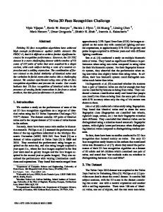
4.5.2 Hardware Interface. Three kinds of peripherals have also been considered : (1) a button box (an electrical box with 24 buttons); (2) a knob box (a box with 9 rotary knobs scanned at a thousand times per second); and (3) a numerical data glove. This interface lets the user assign each peripheral unit to a degree of freedom, and also accepts data into the database for a driver to take account of a new peripheral. Of course, each peripheral unit can be assigned to such general characteristics of the viewer as light, scale, shadow, modes, etc. Furthermore, a complete CT scanner interface has been built into the modeler so that the system may be used in a medical context. Figure 1 shows an aspect of the software interface.
Figure 1
Figure 2
5. APPLICATIONS Over the past 20 years, there has been a great deal of research into off-line programming of robots. The goal has been to create realistic programs for manipulators, and also to take account of most possible real-life situations, including errors, accidents, hidden information and so on. Many developments of the past can today be run in real time on modern workstations. However, the general economic situation has led recently to a fall off in this kind of approach. Recently, “virtual reality” has become the buzz word in computers and the number of applications is growing fast. With this approach, the general problem is the same as with off-line programming of robots. The computerized world has a set of objects with mobile parts between the elements. We have considered this idea of “joints” from a very general point of view. For instance, we can set the scene with a table, an overhead projector on the table, a transparency film over the projector and a picture projected onto a screen. If the table is held by a robot, or even placed on a vehicle, the general model must take into account the particular positions of each part in order to display the picture on the screen. This example suggests the idea of an hierarchical tree where the joints between parts can be fixed, slipped or be deformed.
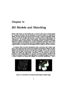
6. THE REALISTIC MODEL OF A HUMAN HAND For validation purposes, and in order to create a “real-world” experience, we have used the AOM system to make the model of a very popular, articulated manipulator: the human hand. The hand has a great number of degrees of freedom : for example, picking up a ball, one of the easiest of movements, for the purposes of this model, requires us to control at least 15 degrees of freedom (21 dof in our case). Three different phases have been used to construct a model of the hand: (1) the geometrical model of each part, using conventional
56
Proc. 2nd Euro. Conf. Disability, Virtual Reality & Assoc. Tech., Skövde, Sweden, 1998 1998 ECDVRAT and University of Reading, UK; ISBN 0 7049 1141 8
software; (2) the editing of the parts in order to set the specific properties; (3) the editing of the joints and their limits. Figure 2 shows a still of the realistic virtual hand and figure 3 includes the articulation axis. Figures 4, 5 and 6 shows three different positions of the same hand.
Figure 3
Figure 4
Figure 5
Figure 6
7. THE 3D CONSTRUCTION OF MEDICAL IMAGES In spite of recent progress in computing, medical imaging has advanced little over the last 50 years. Doctors still study black and white images of extremely poor quality, whether these are body or ultrasonic scans or radiographs. In many cases, the use of realistic 3D models would be really useful, for example, in gaining knowledge of the extent of lesions in order to determine the quantity and kind of chemicals to be used in a treatment (cancer pathology for instance).
Figure 7
Figure 8
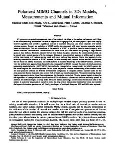
Making a 3D model from a set of 2D images is a very difficult task which requires a significant and expert contribution from the doctor. The problem of distinguishing between healthy and abnormal tissue is still too difficult and specialized for today's computer technology. The AOM system includes a 3D reconstruction model capable of helping the doctor in constructing a 3D image of an organ. This work includes an advanced man-machine interface which helps the doctor to: (1) visualize and edit 2D images in order to identify and extract important areas of tissue; (2) scale 2D images in order to set an homogeneous scale and obtain an original point of reference; (3) manage the model's transparency in order to visualize lesions and take their relative measurements. So far the software has been used for the 3D reconstruction of a lung with major inner lesions, and for a liver with many secondary lesions. Figure 7 includes a 3D view of the liver which has been realized from a set of 25 scanned images. Figure 8 shows a 3D reconstruction of a tumor in a kidney. Proc. 2nd Euro. Conf. Disability, Virtual Reality & Assoc. Tech., Skövde, Sweden, 1998 1998 ECDVRAT and University of Reading, UK; ISBN 0 7049 1141 8
57
8. CONCLUSIONS The high performance of the low cost computers available today permit the manipulation of realistic 3D models. Many field, in which this revolutionary technology might be useful, do no benefit mainly because the interfaces are not well adapted for use by professionals. This situation is particularly acute in the field of medicine where images are still studied and exploited as they were 50 years ago. A crucial factor in the widespread use of computers must be the overall cost of equipment. The software developed here is currently being used by two hospitals in the Paris region and, in each case, this has been achieved by adding only one per cent to the overall running costs of the Medical Images Center. As a result, doctors in both places now have access to an advanced system for processing and studying images, which yields clearer, more accurate and detailed information than hitherto and in less time. In this way, the new system also indirectly helps doctors cope with their principal problem, namely the shortage of man-hours. In the light of this and also considering the situation from the patients’point of view, we can only hope that, in the very near future, this technology becomes universally available to the medical profession. Acknowledgements: For the last 4 years my research team has been working on the manipulation of 3D models. This paper is a summary of our work. The principal student collaborators were Olivier Bedelet, Laurence Chomarat, Olivier Chomarat, Hervé Marechal. The CT scan images were made at the Medical Image Center of the Clinique du Bois de Verrieres (Antony), in Paris area. Thanks are due to Eleanor Gregh and Jim Johnsen for their help in the English version of this paper.
9. REFERENCES [1] M. Krus, P. Bourdot, A. Osorio (1998), Primitive-based management of virtual scenes for a human interactive navigation, Complex Systems Intelligent Systems & Interfaces, Nîmes, may 1998 [2] O. Bedelet (1997), Un système interactif de description d'objets 3d. PhD stage. LIMSI-CNRS, septembre 1997. [3] H. Maréchal (1995), Un langage de description d'objets articulés. PhD stage. LIMSI-CNRS, septembre 1995. [4] O. Chomarat (1994), Interface temps réel pour la manipulation d'objets 3d articulés . PhD stage. LIMSICNRS, juin 1994. [5] L. Chomarat (1993), Représentation 3d d'objets articulés. PhD stage. LIMSI-CNRS, juin 1993.
58
Proc. 2nd Euro. Conf. Disability, Virtual Reality & Assoc. Tech., Skövde, Sweden, 1998 1998 ECDVRAT and University of Reading, UK; ISBN 0 7049 1141 8