MAN-IN-THE-LOOP TRAINING SIMULATOR FOR HYDRAULIC ELEVATING PLATFORMS Erno Keskinen1, Mika Iltanen2, Teemu Salonen2, Sirpa Launis1 Michel Cotsaftis3 & Jorma Pispala4 1
Tampere University of Technology Laboratory of Machine Dynamics P.O.Box 589, FIN-33101 Tampere, Finland Email:
[email protected] 2 Tampere Virtual Reality Center P.O.Box 600, FIN-33101 Tampere Email:
[email protected] 3 Ecole Centrale Electronique Laboratoire des Techniques Mechatroniques et Electroniques 53 Rue de Grenelle, 75007 Paris, France Email:
[email protected] 4 Bronto SkyLift Ltd P.O.Box 553, FIN-33101 Tampere Email:
[email protected] Abstract: Hydraulic elevating platforms are commonly used machinery in assembling outside covers to buildings, washing windows etc. Evacuation of people from high places as well as fire-fighting are also well known service areas of elevating platforms. A team of researchers, designers, and end-users has introduced a concept of a man-in-the-loop simulator to be used in operator training for time-critical and accurate boom maneuvers. The hardware consists of a boom platform mounted on a 3d Stewart platform. Virtual engineering software is used to visualize the working environment on wall screens while a real-time simulation model transforms large boom movements to produce restricted motion in the Stewart mechanism. Keywords: Hydraulic booms, elevating platforms, training simulators, virtual environments
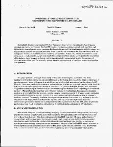
1 INTRODUCTION Elevating platforms are used in assembly works and rescue operations in urban environments. In both work processes a high-rise building or other tall civil engineering construction has to be reached from outside direction without any attachments belonging to the building. The environment is not unstructured as are the off-road working places since the ground (road, street) and the frame of the work object (building) are regularly shaped. The movements of the boom close to the buildings are very dangerous since collision situations may cause collapse of the boom and damages to the building cover during the approach period, and may endanger the operation itself during the working time. On the other hand the requirements for rapid operations are very high. In assembly works the machine costs are high because the total time needed to reach high elevations frequently is long due to the slow approach motion
029_WB2.doc- 1 –
Figure 1. Hydraulic elevating platform.
needed to reach the working target with great care. Similarly, in rescue operations the lifting and lowering maneuvers are extremely time-critical. The efficiency of the working process is strongly operator-dependent, because the number of actuators to be manually controlled is large and the requirement to reach work objects very fast while avoiding collisions is very demanding. Any enhancement to improve the speed and accuracy of maneuvers by means of new technology are therefore very important for the end-users. It has been introduced quite recently solutions [1], where the platform could be used in Cartesian driven mode to follow better vertical and horizontal trajectories very often used in building applications. The main driving mode is still manual although new solutions will probably replace the existing ones in near future. In order to fulfill the strict requirements of accuracy, safety and speed the operators have to follow specific training courses including different maneuvers under controlled conditions. Because the price of the unit is high and the risk to fall in damage or accident situations is always present, a low-cost and more practical way to provide realistic training environment has been introduced to be used in operator training. This environment consists of the platform itself but instead of being mounted on the hydraulic boom the platform is fixed onto a classical 6 d.o.f. Stewart platform [2].
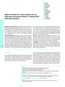
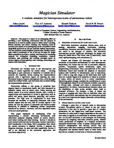
The first link is a chain driven expandable boom with a revolute joint at vehicle frame for turning the boom around the vertical axis and another joint for giving an inclination angle. The second link is the boom arm carrying the platform. The operator is driving the boom standing at the ground level or on the moving platform itself by controlling simultaneously four different actuators for boom turning, boom extension, boom inclination and arm tilting, a situation appearing in figure 2. The valves governing the actuator motions are typically of proportional type. Extension of the three-stage telescopic boom is carried out using chain arrangement shown in figure 3.
2. SYSTEM DESCRIPTION Elevating platform is a hydraulic telescopic boom system consisting of two links and the platform. MOT
DCV2
θ
Figure 3. Chain-driven three-stage telescopic boom. The last joint suspending the platform works under feedback control system, which keeps the platform orientation fixed with respect to vertical direction. The main difficulty for the operator in driving the system is to manage the large number of actuator inputs for producing required Cartesian driving lines instead of curved trajectories, which are typically responding actuator by actuator driving modes.
DCV4 DCV3
3. SYSTEM DYNAMICS θd =0
CYL3
DCV1
Figure 2. Links and actuators in the platform.
The in-plane dynamics of the boom system has been studied and reported in details in [1] and [3]. Very interesting remark is that the system undergoes vibrations in three different frequency scales. The lowest frequency (0.1 Hz) represents the swinging of the boom as a whole structure. The medium frequency range (1 Hz) is related to the tilting movement of the platform arm link whereas the highest frequency (20 Hz) belongs to the platform swinging. This behavior is typical for link-actuator combinations where concentrated springs arising from compliance properties of actuator circuits are joining massive links having distributed elasticity along their spans. A simplified mechanical model of the boom (Fig. 4) consists of beams and joint springs.
029_WB2.doc- 2 –
in picture taken of the laboratory installation (Fig. 7).
Figure 4. Mechanical structure of the vibrating boom mechanism. It is clear that a system being so composed and actuated by joint torque tends to vibrate in eigenmodes shown in figure 5. These modes match exactly to the observed frequencies.
Figure 7. Hardware of the training simulator.
Figure 5. Observed eigenmodes of the boom structure. The dynamics of out-of-plane motion shows behavior, where the torsional mode around the vertical-axis dominates
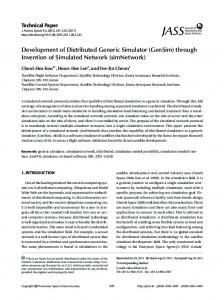
3. SIMULATOR HARDWARE Based on the limitation of spaces available for indoor training purposes the boom structure can not be accepted as a part of the simulator. As an important element of the simulator is to produce accelerations similar to the ones of a real boom, the platform has been mounted on a classical Stewart platform as shown in the system diagram (Fig. 6) and
The platform has a similar joy-stick interface and control panel as in the real system. Platform electronics is installed in control box locating on the floor instead of being mounted on the vehicle frame as in the real unit. The system runs as follows. The operator is giving with the joy-stick an input to drive the system manually in actuator by actuator mode. This input is fed to the control electronics of the proportional valves. Valve board is producing output to govern the valve. Because real valves and actuators are missing this output is transmitted to a computer model of the boom to produce the corresponding dynamic boom response in terms of the 6 d.o.f. motion of the manned platform. This motion will be transformed to the actuator positions of the Stewart platform (Fig. 8) for producing the response motion within the accuracy of the servo actuators used.
Control box Operator platform
Stewart platform
PneumaticValves
Computer boom model
Pneumatic actuators
Model response
Figure 6. System diagram of the simulator concept.
Figure 8. Electro-pneumatically actuated Stewart platform (Virtogo Inc.).
029_WB2.doc- 3 –
4. SIMULATOR DYNAMICS The developed training simulator has clearly similar limitations as aircraft and vehicle simulators typically. Instead of following large amplitude boom trajectories needed in full lifting and turning maneuvers the simulator platform can reach only small areas in the working space. As the platform positions are related to double-integrals of the boom accelerations boom and actuator dynamics have to be modified to produce limited amplitude responses. This transformation should be carried out so that it gives the required transparency for the operator. The motion of the boom typically includes slow large amplitude rigid body motion component combined with small amplitude elastic vibrations. Another important aspect is the constraint of real-time computation requiring fast enough boom simulation model. A complete system model of the elevating platform has been developed earlier in [3] leading to large differential-algebraic system. The arms were modeled as flexible beams and the extension mechanism in the telescopic boom using axially elastic model for the chain. The large number of system variables makes the model too heavy and too slow to be used as a part of the training simulator. Experiments of this full model has led the research team to construct a reduced d.o.f. equivalent rigid link system model for the simulator use. The complete model is divided into two submodels for in-plane and out-of-plane motions. Both models (Fig. 9) consist of rigid boom links connected by hydraulic motors or cylinders.
The bodies for three-stage telescopic boom and platform arm are denoted by subscripts i = 1,2,3,4 while the actuators for boom inclination, arm tilting, boom extension, platform orientation and boom turning around the vertical are numbered by j =1,2,3,4,5 respectively. For simplicity, the platform itself has been reduced to the tip of the platform arm as a concentrated mass with inertia. Another difference in the boom model is the use of motors instead of linear actuators in all revolute joints. The motion of the points in the boom system is followed in cylindrical (r,z,ϕ) coordinate system with Origin fixed to the vertical turning joint locating at offset distance e from the boom inclination joint. The state variables of the boom are (see Fig. 9) relative angle φ1 between boom and base, relative angle φ2 between arm and boom, extension s between the first and second telescopic boom link, absolute angular position θ of the platform with respect to vertical and the rotation angle ψ around the vertical. Recalling that the chain connects the motion of the telescopic boom segments together the Cartesian positions of the mass centers of gravity of each link i=1…4 is L1 e1 − ee r 2 L R2 = s + 2 e1 − eer 2 L R3 = 2 s + 3 e1 − eer 2 L R4 = ( 2 s + L3 ) e1 + 4 e 2 − eer 2
R1 =
θ z
φ2
U1
L4 U2
(1) (2) (3) (4)
while the position of the platform body at arm tip is
R
R = R4 + 2s+L3
a)
R4 e2 2
(5)
The orientation of platform is by definition θ. The Cartesian unit direction vectors are functions of boom and arm orientations
U3
φ1 r
cos φ 1 cosψ e1 = cos φ 1 sin ψ sin φ 1
e
y
cos(φ 1 − φ 2 ) cosψ e = ; 2 cos(φ 1 − φ 2 ) sinψ sin(φ − φ ) 1 2
(6a,b)
The kinetic energy of the system has contributions from linear and angular motions
ψ
b)
2K =
4
4
i= 1
i= 1
∑ M i R i ⋅ R i + ∑ ωi ⋅ I i ωi + MR ⋅ R + ω ⋅ Iω (7)
x
Figure 9. Equivalent rigid link boom models for a) in-plane-motion and b) out-of-plane motion.
where the link and platform inertia matrices are of form
029_WB2.doc- 4 –
L2i 12 0 0 I1 2 Ii = M i 0 Li 12 0 I = 0 0 0 0 ri2
0 I2 0
0 0 (8ab) I 3
The inertia radii of links around their axis is given by ri. The angular velocities in local body coordinate systems are for links i=1,2,3 and 4 φ1 φ1 − φ2 ωi = cos φ 1 ψ ω4 = cos( φ 1 − φ 2 ) ψ (9,10) sin φ ψ sin ( φ − φ ) ψ 1 1 2
Knowing that the large amplitude motion of the boom system is very slow for elevating platforms allows to neglect higher order cross-coupling terms related to coriolis and centripetal accelerations. Straightforward but tedious derivation leads then finally to dynamic equations of motion in form M ( x ) x = G ( x ) + F
where the equations are decoupled corresponding to in-plane, turning around the vertical and platform orientation motions. The state-dependent mass matrix has the following non-zero elements M 11 = M 1
but for the platform
(17)
L21 L + M2 s + 2 4 2
2
2
θ ω = cos θ ψ sin θ ψ
(11)
+ ( 4M + M 4 )
The gravitational potential energy of the boom system is V=
4
∑ M i gRi ⋅ e z + MgR ⋅ e z
i= 1
L + ( M 3 + M 4 + M ) 2s + 3 2 + ( M 4 + 2 M ) L4 ( 2 s + L3 ) cos φ 2
(12)
L24 + 4
δ W = T1δ φ1 − T2δ φ2 + Fδ s + T3 ( δ θ − δ φ1 + δ φ2 ) + T4δ ψ (13) Lagrangian equations for the system take form d ∂K ∂K ∂V − + = Fi dt ∂ xi ∂ xi ∂ xi
(14)
where the xi´s are the elements of state vector φ 1 φ 2 x= s θ ψ
2 L4 ( 2s + L3 ) cos φ 2 − M 4 L4 2 12 = ( M 4 + 2 M ) L4 sin φ 2
M 13
L24 4
(18)
L24 L2 + M4 4 4 12
M 13 2 ( M 4 + 2 M ) L4 cos φ 2 − M 31 M 1 + 4M 3 + 4M 4 + 4M I1
M 23 = − M 31 M 32 M 33 M 44
= = = = 3
i= 1
2 ∑ M i ( Ri ⋅ er ) + cos 2 φ 1
L2i + sin 2 φ 1ri2 12
L2 + M 4 ( R4 ⋅ er ) 2 + cos 2 ( φ 1 − φ 2 ) 4 + sin 2 ( φ 1 − φ 2 ) r42 12
+ M ( R ⋅ e r ) 2 + cos 2 θ I 2 + sin 2 θ I 3 Gravitational load vector G components
and the actuator load vector has elements T1 − T3 − T + T 3 2 F= F T 3 T4
M 22 = ( M 4 + 4 M )
M 55 =
(15)
i= 1
L2i 12
M 12 = − ( M 4 + 2 M )
M 21 = M 12 − ( M 4 + 4 M )
Virtual work done by the actuator forces is
4
∑ Mi
has non-zero
L L G1 = − g M 1 1 + M 2 s + 2 2 2 (16)
029_WB2.doc- 5 –
L + M 3 2 s + 3 + ( M 4 + M )( 2 s + L3 ) cos φ 1 2 L4 − g ( M 4 + 2M ) cos( φ 1 − φ 2 ) 2
L4 cos( φ 1 − φ 2 ) 2 G3 = g ( M 2 + M 3 + M 4 + M ) sin φ 1 G2 = g ( M 4 + 2 M )
(19)
The torques for motors j=1,2,4,5 are calculated from the plus (p) and minus (m) chamber pressures by
o
)
(20)
where Dj is the radian volume of the motor. The linear actuator j=3 for boom extension is generating force F = p3p A p − p3m Am
(21)
The motor chamber pressures for each motor have to be solved from differential equation pair p jp = BV jp
−1
p mj = BV jm
(q (q
−1
p j
) + D Ω )
− D j Ω j
m j
j
t
u j (t ) = U j (t ) + C Dj e j (t ) + C Pj e j (t ) + C Ij ∫ e j (t )dt (26)
j
(22a) (22b)
The servo difference between the current and initial position of actuator j is e j (t ) = z j (0) − z j (t )
The PID part has to be tuned so that it compensates the manual part fast enough to limit the motion amplitudes compatible with the motion restrictions of the Stewart platform. The proposed control rule means practically that the equivalent system always returns to its initial state. For platform orientation driven by actuator 4 there is no manual input and for desired orientation θd = 0 the “real” control rule reads t
with Ω 1 = φ1 , Ω 2 = − φ2 , Ω 4 = θ − φ1 + φ2 , Ω 5 = ψ . while the cylinder pressures are governed by equations q p − A p s p 3p = B 3p (23a) V3 + A p s q3m + Am s V3m + Am ( − s )
(23b)
Factor B states for the bulk modulus of the fluid. Fixed chamber volumes Vjp , Vjm combine oil volumes in piping and hoses by weighting factors 1.05 and 4.0 , respectively, to model the wall compliance of the conduit. Valve flows are in pushing direction q jp = sgn( ps − p jp )cu j
ps − p jp
q mj = − sgn( p mj − pt )cu j
u4 (t ) = C4Dθ(t ) + C4Pθ (t ) + C4I ∫ θ (t )dt
5. VIRTUAL ENVIRONMENT Training simulator provides an environment, where the platform system can be driven with real-like dynamic effects combined with a view of the work object projected on to the screen and following the movements of the platform. So, an essential part of the training simulator is large textile screen, from which the operator can get a look to the real working environment by means of a scrolling image map composed of digital pictures taken from the actual working environment (Fig. 10). Operator control
(24a)
p mj − pt
(24b)
p jp − pt
(25a)
and in pulling direction q jp = sgn( p jp − pt )cu j q mj = − sgn( ps − p mj )cu j
ps − p mj
(25b)
where the flow discharge coefficient −1 −½ c = qnom umax ∆ pnom has been obtained by measuring volumetric flow qnom for fixed pressure difference ∆pnom and full input voltage umax.
(28)
o
Full motion on screen
p 3m = B
(27)
Response of boom model
Limited amplitude motion
(
H j = D j p jp − p mj
Valve inputs uj have open loop manual control part Uj combined with a closed loop PID part for providing smooth return motion for actuators j=1,2,3,5
Response of reduced boom model with PID Figure 10. Lay-out of the training simulator with working environment projected on to the screen.
029_WB2.doc- 6 –
The simulator hardware includes rear projection screens set up in front of the user. The field of the view is 90 degrees and a mono-scope display is used. Together with a combination of spatialized and ambient sound, one can also generate a realistic and captivating 3d-audio environment. The heart of the training simulator is the simulation program, which is written on C. This is the core that organizes the information of the object motions and receives various command inputs. It also controls the interactions between the model and hardware modules, the audio environment, artificial and real time movements of the object actions, and determines the world status. The simulation is basically a discrete process that is iterated once for each time step. As the system moves with reduced amplitudes of motion the screen still is serving the purpose to get the operator to feel the motion acts in full mode. This requires that the image controller has to get information from the large amplitude movement. This could be done by scrolling the image map as synchronized to the motion of the link bodies parallelly computed from the previous equation system (1)…(28), where in equation (26) the open loop part is active only. This means that open loop joy-stick output is controlling the movements on the screen while the dynamic motions of the platform are limited by PID feedback control.
6. SYSTEM REALIZATION The system has been built up in laboratory environment for preliminary tests (Fig. 11). The moving parts of the simulator are attached on steel mounting, which is bolted on the laboratory floor. The boom chair and the rest of the user interface have been connected on top of the actuated platform. In front of the user stands the rear projection screen. The size of the screen is 2.5 m by 2 m. The projector uses LCD technology and locates behind the screen. The resolution of the graphics is currently 1024x768 pixels and the refresh rate exceeds 60 fps.
Figure 11. Training simulator during maneuver in Tampere Virtual Reality Center. The 3d-environment is modeled using 3D Studion MAX software tools. All buildings are textured, so the sense of the immersion is obtained. Also the special equipment for fire-fighting such as highpressure water sprayer is modeled. The simulator software run under PC and uses common application program interfaces as direct-X and direct sound. Therefore the number of the polygons must be limited. The entry lever system hardware is able to handle as much as 10 000 textured polygons. The 3d-audio environment has been created using recorded sound samples. Those signals are processed and sampled separately. The target of processing was to found out the main frequency of each sample and reuse it in future.
7. CONCLUSIONS A training simulator concept has been developed for operator training of hydraulic elevating platforms. Based on physiological operator response, the accent has been put on reproduction of acceleration peaks existing in real system. The simulator consists of elevator platform mounted on classical Stewart platform. Amplitudes of the platform motion are reduced at actuator control level and smaller movements than in the real boom system are produced. This has been done using simplified computer model of the boom system. In order to reach real-time computational speed a simplified computer model of the boom system has been used, where the flexible boom links have been modeled as rigid ones. Large screen, where image maps of the virtual working environment are scrolling and are synchronized to large amplitude platform motions, are completing the system to provide realistic touch to the work process. Preliminary tests show that the introduced simulator concept is working well but the computer model should be developed to represent better state-dependent flexibility of the boom.
REFERENCES [1] Keskinen, E. K., Montonen, J., Launis, S., Cotsaftis, M., "Cartesian Trajectory Control of Hydraulic Elevating Platforms". IASTED International Conference on Robotics and Applications, October 28-30, 1999, Santa Barbara, California, USA. [2] Craig, J.,J., "Introduction to Robotics". 2nd ed. Addison-Wesley, 1989. [3] Keskinen, E. K., Montonen, J., Launis, S., Cotsaftis, M., Simulation of Wire and Chain Mechanisms in Hydraulic Driven Boom Systems. IASTED International Conference on Applied
029_WB2.doc- 7 –
Modelling and Simulation, September 1-3, 1999, Cairns, Queensland, Australia.
029_WB2.doc- 8 –