Journal of Network Systems and Management, VoL 1, No. 4, 1993
Management Information and Its Optimal Allocation for ATM Networks with a Protection Mechanism Satoru Ohta 1'2 and Nobuo Fujii 1
This paper focuses on the definitionand allocation of managementinformationfor ATM broadband networks that adopt the virtual path protection mechanism. The definitionof managementinformationis proposed to represent, in accordance with international standards, a virtual path with the protection mechanism. To achieve accurate representation,the proposed methodfeaturesthe two distinctmanagedobject classes derived from the "trail" concept, which has been specified in ITU-TS recommendations. The allocation of management information is optimized by using computer simulations, The criterion for the optimizationis the rapidity of tracking the change-over/backand setting up a virtual path. The system that exchanges messages and updates managementinformationis modeledas a queueingsystemto evaluate the rapidity. Several alternativeallocation methods are compared, and the best method is determined. KEY WORDS: ATM; TMN; network management; network survivability; performance evaluation.
1. ~ T R O D U C T I O N In designing a telecommunication network management system, one important process is to determine m a n a g e m e n t information appropriately according to the Telecommunication Management Networks (TMN) concept recommended by I T U - T S [1]. Since T M N employs interoperable interfaces based on OSI system management [2], m a n a g e m e n t information is modeled as managed objects representing network resources and support objects that store other information needed for management. Additionally, the T M N recommendation has identified several types of operations system functions [1]. This leads to another design decision, i.e., how to allocate the managed objects among network elements 1NTT TransmissionSystems Laboratories, Yokosuka-shi, Japan. 2Correspondence should be directed to Satom Ohta, NTT Transmission Systems Laboratories, 1-2356 Take, Yokosuka-shi,238-03, Japan. (E-mail:
[email protected].) 373 1064-7570/93/1200-0373507.0010 © 1993 Plenum Publishing Corporation
374
Ohta and Fujii
and various operations systems. These design processes must be executed to satisfy technical and functional requirements specific to the network to be managed. This paper deals with management systems for the ATM broadband networks that support the virtual path restoration function. The virtual path restoration function has been treated in several papers [3-7], and these studies suggest that ATM is a powerful transport technique from the viewpoints of flexibility for mixed traffic, as well as its support of new service restoration methods. Modem service restoration techniques require the network elements to offer more functionalities than are currently supported. Although the network can be rapidly restored through the autonomous activities of such intelligent network elements, the restoration techniques offer an important technical problem to be solved in the design of network management systems. Namely, the network management system must have the most complete and latest knowledge about the network reconfiguration performed by the network elements to achieve consistent management. Thus, if the network is reconfigured by network elements due to failure, the managed objects must be quickly modified to match the changes made in the network resources. To satisfy this requirement the effective definitions and optimal allocation of managed objects should be developed. Although several restoration techniques have been proposed [5-9], this paper defines the managed objects for the network adopting virtual path protection switching with pre-set stand-by connections [5-7]. The feature of the proposed information model is the employment of two distinct managed object classes derived from the "trail" concept, which has been specified in ITU-TS recommendations [10]. These object classes enable a virtual path with the considered restoration scheme to be represented accurately. The highlight of this paper is the simulation study that was carried out to allocate managed objects optimally in a systematic manner. The criterion for optimization is the processing time needed to track the change-over/back and set up of a virtual path. To evaluate the processing time, the system that exchanges messages and updates management information is modeled as a queueing system, an approach that is often used for evaluating the performance of computer systems [11]. Several alternative allocation methods are shown to offer different processing times, and the best method is determined. In Section 2, virtual path protection switching, which is the foundation of this study, is described. Section 3 outlines management systems for the ATM network supporting the protection mechanism. The contents of this section include functional and technical requirements for management, the structure of the management system, and the basic managed object classes, which can be immediately derived from the standards. The definition and effectiveness of the Virtual Path Capability managed object are described in Section 4. Finally,
Management Information and Its Optimal Allocation for A'I'M Networks
375
Section 5 shows the effect of allocating managed objects and the optimal allocation method derived from the simulation results. 2. RESTORATION USING PRE-ASSIGNED STAND-BY VIRTUAL PATHS
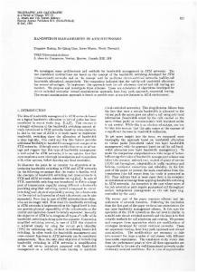
When a failure occurs in a network resource, the damaged virtual path can be automatically restored by several methods. One method is the "self-healing" technique [6, 7]. When a failure is detected, this method discovers and sets up a new route for a damaged path through the distributed and autonomous control of network elements. Here, the "flooding" technique is used to discover new alternate mutes. Another method is the line protection switching, which is implemented by the change-over function placed in the termination points of a transmission link [8, 91. This function restores the virtual path by switching the failed transmission link to a stand-by link. The third method is virtual path protection switching, which switches the damaged virtual path to a predetermined alternate route [5-7]. This change-over is autonomously executed by management functions embedded in virtual path termination points and ATM cross-connect systems. Each technique has its own advantages in an appropriate application area. Thus, it is possible, in practice, to combine several methods to utilize the merits of each method. Nevertheless, this paper assumes virtual path protection switching as the fundamental restoration mechanism of ATM networks. This is because virtual path switching has many useful characteristics though it may be less flexible than self-healing and less speedy than line protection switching. First, spare transmission capacity is effectively shared among several protected virtual paths with this method. Thus, facility cost is tower than is possible with line protection switching. Additionally, no system response is needed from the intermediate cross-connects supporting the alternate mutes during restoration. Therefore, the method incurs less processing load than self-healing. These advantages are achieved by the independency of routing and capacity in ATM networks [5-7]. Moreover, because it is not necessary to search for new routes at change-over, the method can restore communication services more quickly than can self-healing. Figure 1 illustrates virtual path protection switching. For each virtual path, alternate mutes are pre-determined, and the corresponding cross-connect controt information is down-loaded to each ATM cross-connect system. Thus, stand-by connections are made along the alternate routes in advance. In the normal operating state, cells are not sent to these connections. If a failure occurs in a link or an intermediate cross-connect system on the original route, the sink termination point can detect it through the VP-AIS (Alarm Indication Signal) or the continuity check mechanism specified in Ref.
376
Ohta and Fujii ATM cross-connect .... ~ m
Stand-by connections
ATM cross-connect
c
L
c
n
system
cross-connect system
Fig. 1. Virtual Path ProtectionSwitchingUsing a Stand-ByRoute. 12. The sink termination point then sends back the message that triggers changeover to the source termination point. This message can be sent through, for example, pre-deterrnined alternate routes [6, 7]. Upon receiving the message, the source termination point autonomously changes the route to one of the preassigned alternate routes. The termination point executes this change-over by setting the initial virtual path identifier (VPI [13]) of cells to the value of the stand-by connection selected. The intermediate ATM cross-connect systems forward cells based on cross-connect control information. No changes are needed in the cross-connect control information because the connections needed for change-over have been set up beforehand. To prevent the change-overs from causing traffic congestion, the existence of sufficient idle capacity is confirmed by each ATM cross-connect system on the alternate route before restoration. This confirmation is requested by the termination point using OAM cells [6, 7]. Meanwhile, continuity verification of the alternate connection is also needed to assure that the connection is available for change-over. If the failed resource is restored, the management system initiates changeback by ordering the termination point to send cells to the original connection. The termination point completes this order by resetting the initial VPIs of cells to the original value. 3. M A N A G E M E N T SYSTEM 3.1. Requirements for Management The virtual path protection technique described earlier requires management functions to be embedded into the network elements. Such network elements autonomously reconfigure the network to restore damaged virtual paths.
Management Information and Its Optimal Allocation for ATNINetworks
377
OAM cells are used for management communications to achieve this autonomous reconfiguration. The autonomous control by network elements will significantly improve the rapidity of restoring services in comparison to the centralized-control scheme. However, such a control scheme requires the network management systems to have a unique capability. That is, the network management systems must have a sufficient knowledge of the network configuration changes, which will be induced through the autonomous activities of network elements. If the system can not grasp the exact current network configuration and resource usage, a resource may be overused or an operation may not be executed correctly. Thus, an important technical requirement for the management system is rapidity in tracking network reconfiguration. To increase network manageability by interconnecting management systems and network elements, including those of other ATM broadband networks, standard interoperable interfaces must be introduced. This means that management systems should comply with the TMN architecture [1] and make use of OSI systems management standards [2] to implement management interfaces. Specifically, management information must be defined and registered according to these international standards. Also, the information will be transferred via standardized management protocols. So that the management system can accurately know the status of network resources, the management information is used as a means of representation. Since the change-over of a virtual path alters network resources, the management information should be correspondingly modified. The definition and location of management information may affect the amount of the processing and communication load induced by this modification. To track reconfiguration rapidly, therefore, we must determine the appropriate definition and location of the management information. When the failed part of the network is repaired, the configuration must be returned to the initial state. The management system should change-back the reconfigured connections to the original configuration when the repair is completed. Quick change-back is also required as a management system function. This also modifies the management information. Thus, speed of change-back should be considered in defining management information as well. Other operations such as virtual path set-up or stand-by route reconfiguration are also executed through modification of management information. Management information should be such that these operations are executed smoothly. 3.2. Management System Model
This paper assumes a network management system based on the TMN hierarchical architecture, which categorizes operations system functions (OSFs) into the business, service, network and basic OSFs [1]. According to this cate-
378
Ohta and Fujii
gorization of OSFs, the assumed model adopts the following management levels as shown in Fig. 2. * Network element level: Functions of this management level are allocated to network elements (NEs). The purpose of these functions is to correctly operate NEs. This level defines and manages the status of each NE, which is treated independently from those of other NEs. • Network element management level: Functions of this management level are allocated to management systems referred to as network element management systems (NEMSs). These systems are in charge of coordinating the NEs and controlling the configuration of the network. The status of network function is defined and managed in this level. To handle the distributed nature of the network efficiently, NEMSs may be distributed to multiple places according to geographical or organizational requirements. * Network management level: Functions of this management level are allocated to management systems called network management systems (NMSs). These systems are in charge of managing network services. For this purpose, an NMS can control the network configuration. In the network management level, the status of network services is defined and managed. To achieve this, an NMS gathers and processes the network function status, which are defined in the network element management level. At this level, there are also some management support systems to manage network planning, work force, network assets, customer support, etc. Considering the variety of network services possible, NMSs may be distributed among several locations corresponding to the types of network services. o Network operator level: Functions of this management level are allocated to work stations (WSs). WSs provide customized views of the network to network managers and operators to meet their various needs.
Network Operator
,letwork Management
~.lementManagement
Network Element
Fig. 2. Management System Model Based on the TMN Architecture.
ManagementInformationand Its Optimal Allocationfor ATM Networks
379
WSs gather appropriate information from NMSs to provide views of the network. 3.3. Management Information Representing Virtual Path
3.3.1. Managed Objects Management information utilized in management systems must be forreally defined in accordance with the Generic Network Model [10] and the Guidelines for Definitions of Managed Objects (GDMO) [14]. Almost all management information for ATM networks can be derived by reusing management information definitions made in ITU-TS and ISO. This paper assumes the following managed object classes, which are immediately derived from management information definitions made in ITU-TS and ISO. (1) ATM cross-connect system (ATM XC system): This managed object class represents the characteristics of an ATM cross-connect system receiving management orders from management system(s). (2) Link: This managed object class represents a transmission facility between ATM cross-connect systems. (3) Virtual path link (VPL): This managed object class represents the communication capability provided by ATM cells associated with a unique virtual path identifier (VPI) in a link. Attributes of a VPL managed object include VPI and service status. (4) Virtual path (VP): This managed object class is based on the trail concept introduced by Ref. 10 and represents the communication capability between two communication endpoints. Attributes of a VP managed object include termination point names, assigned capacity, and stares. (5) Virtual path termination point (TP): This managed object class represents the communication endpoint of a virtual path. (6) Virtual path link cross-connect (XC): This managed object class represents the relationship between incoming VPL and outgoing VPL. The relationship is used to set up the cross-connect switch of an ATM cross-connect system° Fig. 3 illustrates an ATM network by using managed objects.
3.3.2. Relationship of Managed Objects Between the managed objects, the relationships of containment and component are defined. These relationships lead to existence dependencies which can affect procedures executed in operations as shown later. A containment relationship consists of a managed object that has a containing role and managed objects acting in a contained role. The latter objects exhibit an existence dependency to the former. On the other hand, a component relationship consists of a managed object with a composing role and managed
380
Ohta and Fujii
ATM XC system: ATM cross-connect system
VP: Virtual path TP: Virtual path termination point XC: Virtual path link cross-connect
VPL: Virtual path link
Fig. 3. Managed Objects Representing an ATM Network.
I ATMXC SystemI
I-~
c°mp°nent~mponent
~mpa~ng~.] ATM XC system: ATM cross.Connect System VP: Virtual path TP: Virtual path termination point relationship object XC: Virtual path link cross-connect Vrolel I VPL: Virtual path link
Fig. 4. Relationship Diagram of Managed Objects in ATM Networks.
objects that take the component role. A managed object-composing role establishes an existence dependency with a set of managed objects-component role. Namely', a managed object-composing role only exists when its components exist. Figure 4 depicts these relationships between managed objects as defined for an ATM network. 4. " V P C " MANAGED OBJECT The definition of the VP managed object and its relationship to other management information should be carefully considered to simplify the procedures needed to update management information. For this purpose, a Virtual Path Capability managed object is introduced in addition to the managed objects mentioned in Section 3.3.
Management Information and Its Optimal Allocation for ATM Networks
381
4.1. Representation by Basic Managed Objects
Let us observe more precisely how the protection mechanism is represented by the managed object definitions described in Section 3.3.1. The first observation is that no VP managed object should be created nor deleted by change-over. This is because communication capability that a VP managed object represents is maintained after the route change. However, change-over alters links or cross-connections that the virtual path uses. This change must be reflected in management information and thus a reference from a VP managed object to virtual path components is necessary. A termination point has the capability of replacing its originally assigned initial VPI with the VPI of a stand-by route. To represent and control this capability, the initial VPI attribute of TP managed object is indispensable. Figure 5 summarizes the management information related to virtual path protection switching. Note that the management system only recognizes the stand-by route as a set of managed objects not as a managed object. 4.2. Virtual Path Capability The previously mentioned VP representation has a problem in that some significant characteristics of the network are not explicitly represented. These characteristics are: (a) existence of a stand-by route, (b) whether a virtual path is in a normal or changed-over state, and
+Nt ste VP Stand-by route Direction VP: Virtual path TP: Virtual path termination point ×C: Virtual path link cr~s-connect VPL: V+r~al ~ t h link
Fig, 5. Representation of a Virtual Path Using Only the Basic Managed Objects Described in Section
3.3.
382
Ohta and Fujii
(c) in what order multiple stand-by routes are searched to conduct changeover. By representing these characteristics in management information explicitly, some operations can be performed more smoothly. For example, consider the case of deleting and configuring a stand-by route. To describe these characteristics, a new managed object class called Virtual Path Capability (VPC) is introduced. A VPC managed object represents the connectivity of one alternative route between termination points. Here, the route may be a stand-by route or a route that is being used as a virtual path. While only one VP managed object instance is created for a virtual path to represent its connectivity independently from the routes, multiple VPC managed object instances can be created corresponding to pre-determined routes. A VPC managed object has attributes indicating the components that construct the connection. Figure 6 depicts the introduction of the VPC managed object to the virtual path representation. Since virtual path components are now identified through a VPC managed object, referencing from a VP is not needed. With this scheme, the existence of a stand-by route is clearly represented. Both the VPC managed object and VP managed object correspond to the trail concept specified in the ITU-TS Recommendation M.3100 [10]. Moreover, the resource represented by these managed objects is the virtual channel connection defined in Ref. 13. Thus, the concept of the VPC managed object class is based on the existing ITU-TS recommendations. However, no recommendations have defined the way of representing the trail of a virtual path with two distinct object classes. This employment of the distinct object classes leads to the clear description of the characteristics mentioned earlier.
] vP ]
initial
~
vP,
i . ~I i. VPC
/-
_ H
Stand-by route
uu.i.pui=ul.l¢r , ~ , u ~
Direction VP: Virtual path TP: Virtual path termination point XC: Virtual path link cross-connect VPL: Virtual path link VPC: Virtual path capability
Fig. 6. Modified Virtual Path Representation Using VPC Managed Objects.
Management Information and Its Optimal Allocation for ATM Networks
383
Another notable feature of VPC managed objects is the introduction of fallback relationship and backup relationship between VPCs [15]. The characteristics (b) and (c) are successfully described by using these relationships. In addition, it can show each VPC's role; for normal usage or for stand-by against failure. In order to represent these relationships, a VPC managed object has the following attributes. ® Primary VPC name: Name of VPC managed object that can be backed up, . Secondary VPC name: Name of VPC managed object available as back up, ® Backed-up VPC name: Name of VPC managed object currently backed up, ® Back-up VPC name: Name of a VPC managed object which is backing up now. Figure 7 depicts the role of each attribute before and after change-over was made.
4.3. Change-Over and Back Using VPC Managed Objects The route providing communications is selected by determining the initial VPI at the source termination point. Therefore, if a virtual path is changed over under the autonomous control of the termination point represented by a TP managed object, the initial VPI attribute of the TP must be modified. Section 2 describes how the source termination point initiates the change-over. On the other hand, change-back is executed through the initial VPI modification that is requested by the management system. original VPC
secondaryVPC name
stand-by VPC
- primary VPC name back-up VPC name backed-+p VPC name NULL original VPC ~secondary
back-up
"Before restoration"
NULL
stand-by VPC VPC n a m e ~ . ~ . . ~
primaryVPCname~acke6-u VPCname "After restoration"
Fig. 7. Attributes Representing Fallback and Backup Relationships Before and After Change-Over.
384
Ohta and Fujii
While the TP managed object is modified at change-over and back, the VPC managed objects are also updated. As illustrated in Fig. 7, change-over induces modification of the back-up VPC attribute of the original VPC and backed-up VPC attribute of the stand-by VPC. After change-back is completed, these attributes are replaced by the original value. This alteration of back-up relation is initiated by the TP managed object. Note that the VP managed object is not disturbed at change-over and back. 5. OPTIMAL ALLOCATION OF MANAGEMENT INFORMATION 5.1. Effects of Managed Object Allocations In the hierarchical architecture of Fig. 2, there are three locations to which management information will be allocated: Network Element (NE), Network Element Management System (NEMS), and Network Management System (NMS). Rapidity of the completion of processes induced by change-over/back depends not only on managed object definitions but atso on allocations of the managed objects described above. This is because the number of exchanged messages differs with the allocating method employed, as does the processing and traffic loads placed on TMN. Moreover, the placement of managed objects may affect the degree of load concentration to a particular network element or management system. This also influences processing time for managed object modification. For the same reasons, other operations such as set-up of virtual paths may also be influenced by the locations of managed objects. Therefore, it is important to optimize the method of allocating the managed objects to network elements or management systems for satisfying the technical requirements identified in Section 3.1. Since there are a large number of alternative allocating methods, it is very hard to exhaustively examine all of them. Thus, we consider only the three alternatives shown in Table I for simplicity. The three methods are derived by
Table I. ATM Managed Object Allocation I
I
Allocation Method
Network Element (NE)
NE Management System (NEMS)
A
ATM XC system, XC, TP ATM XC system, XC, TP ATM XC system, XC, TP, VPC
Link, VPL
VP, VPC
Link, VPL, VPC
VP
Link, VPL
VP
B C
II
Network Management System (NMS)
Management Information and Its Optimal Allocation far ATM Networks
385
placing the VPC managed object to either the NE, NEMS, or NMS. The locations of other management information are the same for all methods. Although a VPC is associated with a network configuration, it is valid to allocate the VPC to the NE. This is because the VPC also represents information needed to manage a termination point. For example, consider the case that management needs to know whether a termination point has executed changeover or not. Since the TP managed object does not explicitly show this information, the VPCs must be referred to. Because of this relation between a VPC and a termination point, method C becomes a possible alternative allocation scheme. These allocation methods require the following management communications for the change-over, change-back and set-up of virtual paths. (1) Management communications for change-over When a faulty virtual path is changed-over, managed object modifications are initiated by the underlying resource of a TP. This generates the management communications shown in Fig. 8. Note that the attribute value change in a TP managed object does not require message exchange because it is executed internally within an NE. Also, since method C allocates VPC managed objects at the NE including the TP, the attributes of VPCs are changed in the NE and thus no communications are needed. With methods A and B, communications are necessary to change the attributes of backed-up VPC and back-up VPC. (2) Management communications for change-back If the failure is recovered, the NMS initiates change-back by sending a message to the TP managed object. After confirming change-back at the TP, attributes in the backed-up and back-up VPCs are reset. Figure 9 summarizes communications needed to execute this process. Again, method C does not need
NE
NEMS
NE
Method B
NMS
VPCModifica~n
~lethodA
[
NEMS
NMS
NEMS
NMS
VPCMo~fiation~ NE
Method C
Fig. 8. ManagementCommunicationsfor VPC Change-Over.
386
Ohta and Fujii NE Method A
NE
NMS
NEMS
NMS
I vPcChange-Back VPC Modification
Method B
NE Method C
NEMS
VPC Change-Back VPC Modification
NEM$
NM,S
VPC Change-Back
Fig. 9. Management Communications for VPC Change-Back.
communication for these VPC attribute changes because the process is executed internally in the NE. (3) Management communications for virtual path set-up Set-up of a virtual path must be carried out through the following steps because of the existence dependency between managed objects. • XC, VPL, TP creation • VPC creation • VPC set-up to define back-up relation • TP set-up to define initial VPI from VPC information • VP creation Figure 10 indicates management communications needed for virtual path set-up with each managed object allocation rule. In Fig. 10, it is assumed that TP set-up is executed as a side effect of VPC set in method C. Note that communications of response for the operations are also necessary to assure the order of the steps described earlier. 5.2. Simulation Study The optimal allocation of managed objects was determined through computer simulations. The simulations clearly showed how the alternative allocation methods influence the time taken to modify management information. 5.2.1. Measures
The simulations examined the following performance measures. (1) Time to complete the attribute modifications induced by changing over damaged paths (Charge-over tracking time).
Management Infermation and Its Optimal Allocation for ATM Netwerks NE
NEMS
I
MethodA
I
387
NMS
XCCreation TPCreation TPSet-Up
NE
I
[
VpILCreati°nNMS
~-,.41
XCcreation
[
MethodB
~
) " %•,, I
~ --
NE
-,,-~.
VPCCreation VPCBet-Up
~NEMS .~VPL
1
XCCreation
}
VPCCreation
1
NMS Creation
MethodC
] .....
: Request
. . . . ID-:
___
........ : 2 2 L . . : . . : 2 . _ . I_.......... im~
Response
Fig. 11). Management Communications for VP Creation.
(2) Time to complete the attribute modifications induced by changing back the restored paths (Change-back tracking time). (3) Time to complete set-up of a virtual path including an alternate standby route. (Virtual path set-up time). To estimate these values, two types of simulations were carried out. One investigated measures (1) and (2) here, while the other evaluated (3). The former is referred to as the failure/repair simulation, while the latter is named the set-up simulation hereafter. I n a realistic A T M network, management systems deal with various operations other than change-over, change-back, and virtual path set-up. Taking this fact into account, the simulations assumed the existence of other such operations. The performance measures were recorded against the processing load induced by these other operations.
388
Ohta and Fujii
5.2.2. Simulation Model (1) Systems. Systems associated with the operations described include NEs, NEMSs, and NMSs. The simulations employed the single queue model shown in Fig. 11 to represent each system. A job fed to the model is concerned with either modification, creation, or deletion of one managed object. The jobs are categorized into message transmission, message receipt, and intemal processing. Each job is processed in the system as follows. • message transmission: A job is generated at a managed object or an application. It then passes to the queue. After it is processed by the server, it goes to the destination system. The job simulates, for example, an operation request process at a managing system. • message receipt: A job comes in from a source system and goes into the queue. After being processed by the server, it terminates at a managed object or an application. The job corresponds to, for example, an operation request process at a managed system. • internal process: A job is generated at a managed object or an application. It goes into the queue. After being processed, the job terminates at a managed object or an application. This simulates a modification made locally in the system.
(2) Virtual Path Network. The simulations employed the 6-node ring network shown in Fig. 12 as a model of the managed ATM network. In the failure/ repair simulation, the failure occurs repeatedly at the link between node 2 and node 3. The paths included in this link are as follows: • 50 virtual paths (in each direction) between node 1 and 3. • 50 virtual paths between node 1 and 4. • 50 virtual paths between node 2 and 3. The set-up simulation considers the set-up of a virtual path and its standby connection between node 1 and node 4. Thus, one VP, two VPCs, and the
NE, NUMS, or NMS Managed Object or Application
Fig. 11. Model for a Management System and a Network Element.
Management Information and Its Optimal ALlocation for ATM Networks
389
associated managed objects representing the components are created and setup. (3) TMN. The simulated TMN consists of one NMS, three NEMSs, and six NEs as shown in Fig 13. The NEs correspond to the nodes in Fig. 12. In Fig. 13, the arrows show the relations for which messages are exchanged to execute operations other than change over/back and virtual path set-up. It was assumed that inter-system communication is sufficiently rapid so that communication delay is negligible. (4) Parameters. Each type of simulation considered two cases. In case 1, the NEs, NEMS, and NMS had identical processing capability. By contrast, case 2 assumed that the processing capability of NEMS and NMS was 10 times greater than that of the NEs. For each case, time between the occurrences of operations other than change-over/back and virtual path set-up was assumed to be distributed randomly according to an exponential distribution with mean value t, (seconds). That is, these operations happen according to a Poisson process [16]. Such an operation was generated for one of the l~elations shown in Fig. 13 with equal probability. Considering that there may be various kinds of operations, the service time at each server for a job induced by such an operation varies randomly
I
6
Failure
--O
5
Fig. 12. The Simulated ATM Network,
MS
NodeI
0
Node2 Node3 Node4 Node5
0
Node6
Fig. 13. The Simulated Heirarchical Management System.
390
Ohta and Fujii
according to the exponential distribution. In case 1, the mean value of the service time was assumed to be 0.5 (seconds) for every system. This value of the service time was selected to be practically achievable with existing technologies as suggested by the experimental results [17, 18]. Meanwhile, it was set at 0.5 (seconds) for NEs and 0.05 (seconds) for NEMSs and NMSs in case 2 because of the assumption made regarding the processing capability. Let the load on a system be represented by the utilization factor p, which is defined as, P = (job arrival rate) x (service time). Let p for the NMS or NEMS be Pl, and let that for an NE be P2. Then, 1
P~ < Pl = 6ta' for case 1, and 1
Pl < 02 = 18ta' for case 2. In the failure/repair simulation, a failure was assumed to occur every 3 x 10⁴ seconds. The interval between failures was set sufficiently long so that the processing loads induced by successive failures would not interfere with each other. After a failure, jobs are generated at NEs that request attribute modifications in TPs, original VPCs, and stand-by VPCs. Link repair also generates jobs to reset the modified attributes to the original values. The repair is done 1.5 x 10⁴ seconds after the failure. The interval between the failure and repair was determined to be sufficiently large so that the processing time associated with change-back would be measured independently from the processing load induced by change-over. In case 1, the service time for such a job was constant (0.5 seconds) for message transmission/receipt and (0.2 seconds) for an internal process at all systems. Again, these values were chosen to be practically achievable with existing technologies. For the internal process, the service time was decreased because no communication-related processing is necessary. In case 2, the service time of an NE was the same as in case 1. However, that of the NMS or NEMS was set at 0.05 seconds for message transmission/receipt and 0.02 seconds for the internal process to take account of the processing power assumption. Failures and repairs occurred 20 times, and the averaged values of the performance measures were recorded. Set-up of a virtual path was repeated 20 times every 3 x 10³ seconds in the set-up simulation. The interval between set-ups was selected to be sufficiently large so that successive set-ups would not interfere with each other. The service time of each system was identical to the failure/repair simulation. The generation of jobs follow the procedure described in Section 5.1. Figure 14 depicts the flow chart of the virtual path set-up scenario for method A.
NLanagement Information and Its Optimal Allocation for ATM Networks NMS
NEMS
;
Send XCe, VPLe, and-'-]
391
NE
::
~ t PLhaebeen [ I created, send the
t I
i i
l IfanXCarTPhasbeen ] created, send the I response
t
tXCs, VPLs and TPs t v ocs f If all VPCs have been created, set up the VPCs [Send TP set-up requests I If the TP has been set up, send the responsei J If all responsesof the TP t set-ups have been I confirmed, create the VP] (
End
'
)
Fig. 14. Flowchart of Virtual Path Set-Up Scenario for Method A.
1000
~ k~
[ 95% Confidence Method ---I--Method Method
800
Interval A 8 C
i
i ~Z
60o
LU
400
e._~ _..-=e"~ Z < o
200
!
&O
0.2
0,4
0,6
0.8
t.0
LOAD ON NMS (NEMS), ,ol
Fig. 15. Change-Over Tracking Time vs. the Load on NMS/NEMS for Case 1.
O h t a and Fujii
392
5.2.3. Results Figures 15 and 16 show change-over tracking time versus the load on NMS/NE for case 1 and case 2. In these figures, the x-axis represents p~ for case 1 and P2 for case 2. Similarly, change-back tracking time is plotted against load on system in Figs. 17 and 18 for case 1 and case 2. All of these figures show that method C offers the least tracking time, and that the performance with method A is worst. 250
LU I-(.9 Z
20o v
150
rr tu
100
m z