IEEE TRANSACTIONS ON MAGNETICS, VOL. 42, NO. 4, APRIL 2006
1183
Manifold-Mapping Optimization Applied to Linear Actuator Design D. Echeverría1 , D. Lahaye1 , L. Encica2 , E. A. Lomonova2 , P. W. Hemker1 , and A. J. A. Vandenput2 Centre for Mathematics and Computer Science (CWI), 1098 SJ Amsterdam, The Netherlands Eindhoven University of Technology (TU/e), 5600 MB Eindhoven, The Netherlands Optimization procedures, in practice, are based on highly accurate models that typically have an excessive computational cost. By exploiting auxiliary models that are less accurate, but much cheaper to compute, space mapping (SM) has been reported to accelerate such procedures. However, the SM solution does not always coincide with the accurate model optimum. We introduce manifold mapping, an improved version of SM that finds this precise solution with the same computational efficiency. By two examples in linear actuator design, we show that our technique delivers a significant speedup compared to other optimization schemes. Index Terms—Actuators, optimization methods, space mapping (SM), surrogate-based optimization.
I. INTRODUCTION
or, more generally, by minimizing with the surrogate
M
ANY practical design problems in electromagnetics are nowadays solved by means of highly accurate computational models. Typically, finite elements (FEs) are employed. However, this approach is computationally expensive. The space-mapping (SM) technique [1] aims at accelerating such procedures using approximate models that are faster to compute. The application of SM to optimization in low-frequency electromagnetics was considered, e.g., in [2]. The originally conceived SM technique might fail to converge to the accurate model optimum. We introduce manifold mapping (MM) [3], an improved SM technique that efficiently finds the desired optimum. Its application is illustrated with some examples. II. SM AND MM A. SM Technique
Let us consider an optimization problem in the design space with specifications . The accurate behavior of electromechanical devices is often studied using models that have large computational costs, e.g., FE models. In SM terminology, these models are called fine models. The , where is the fine model response is denoted by design variable. The associated optimum is referred to as . SM needs a second, possibly less accurate but computationally much cheaper model. This is the coarse model; in this paper, the coarse models are assumed to be defined over the same design space . The coarse model response and the corresponding opand , respectively. timum are denoted by The SM function is defined by
(3) However, the solution of neither of these two problems does necessarily coincide with the fine model optimum . B. MM Technique Analyzing the conditions under which the SM solution yields the correct answer, the SM technique can be improved in such a way that the accurate optimal design can be computed by an iterative process. Each step in this scheme requires one evaluation and one solution of a cheap minimization of the fine model problem. by an arbitrary bijection MM replaces the SM function and introduces the manifold mapping . With this mapping, the point is mapped to and at to the tangent space for the tangent space for at . By this construction, then
In the examples in this work, the function to the identity.
is taken equal
C. Implementation of MM During the iterative solution process, the manifold mapping is approximated by a sequence of affine mappings . an This leads to the following algorithm (with arbitrary bijection). 1) Set and compute
(1) SM corrects , the coarse optimum, in order to approximate . In traditional SM, this is done either by solving the nonlinear system of equations (2)
Digital Object Identifier 10.1109/TMAG.2006.870969
2) Evaluate and stopping criteria are met. and with 3) If
and finish if appropriate
and , we define and to be the matrices with, reand as columns. Their singular value spectively, and decompositions are, respectively, .
0018-9464/$20.00 © 2006 IEEE
1184
IEEE TRANSACTIONS ON MAGNETICS, VOL. 42, NO. 4, APRIL 2006
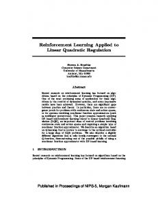
Fig. 1. Axisymmetrical geometry and design variables of (left) the automotive and (right) the voice-coil actuator. Fig. 2. Force responses for the fine and coarse model in two points of
X.
4) The approximate affine mapping is (4)
TABLE I FORCE OPTIMIZATION OF THE AUTOMOTIVE ACTUATOR IN THE ORIGINAL DESIGN SPACE
where is a regular matrix equal to the identity and to if for . The operator denotes the pseudoinverse. 5) Compute
6) Set k = k + 1 and go to 2. Step 5) can be implemented in a simpler way since it can be shown that it is asymptotically equivalent to the following: 5) Compute
where
The matrix
satisfies
for and , and, thus, in the limit, the desirable properties of the manifold mapping are fulfilled. Under convergence of the scheme given, the limit is the fine model optimum . III. AUTOMOTIVE MAGNETIC ACTUATOR For this first actuator design problem, SM, MM, and some other efficient optimization techniques are compared. Automotive actuators typically generate high levels of force and can be used in devices, such as electromagnetic switches, relays, valves, etc. Fig. 1 is a schematic view of the cylindrical plunger electromagnet. It was originally introduced in [4], and it consists of a core and a plunger, both made of iron, and a copper have to be optimized in order to coil. The sizes assure a maximum magnetic thrust force versus displacement
in the axis. The volume of the device is kept constant. The specifications are a constant force response of 100 , for six proposed vertical plunger displacements. The design space , where all the bounds in [4] is the rectangle have been specified in millimeters. More details on the problem can be found in [4], [5]. is based on a static force computation The fine model for the six plunger displacements. This force is evaluated numerically by second-order Lagrangian FEs [6] with one level of adaptive refinement. The number of degrees of freedom in every case is around 5000–7000 yielding three digits of accuracy in the force. The objective function here is , i.e., a relative 2–norm of the model discrepancy. is based on a magnetic equivalent cirThe coarse model cuit (MEC) [7] derived from the actuator. The MEC is nonlinear, in the sense that the – curve is considered for the plunger. The core magnetic permeability is taken as infinite and neither fringing nor leakage effects are included. A linear interpolation for the force is taken between the points for maximum and minimum displacement. This coarse model is around 400 times faster than the fine one. In Fig. 2, the fine and coarse model responses are shown for two points in the design space : the geand the optimum obtained with MM. Each ometrical center optimization involving the coarse model is solved by sequential quadratic programming (SQP) [8]. Table I shows the performance of seven minimization methods when applied to the mentioned fine model. The given figures (amount of work expressed in the number of equivalent fine model evaluations) are approximately proportional to the total computing time. All seven techniques yield solutions with similar objective function values. The first two (MMA: method
ECHEVERRÍA et al.: MANIFOLD-MAPPING OPTIMIZATION APPLIED TO LINEAR ACTUATOR DESIGN
1185
TABLE II FORCE OPTIMIZATION OF THE AUTOMOTIVE ACTUATOR IN THE MODIFIED DESIGN SPACE
of moving asymptotes and PM: penalty method) correspond to methods analyzed in [4] and the next two (EM: ellipsoid method and RQP: recursive quadratic programming) to other schemes also studied by the same author [5]. The coarse model mm mm has a lower fine cost function optimum than any of the solutions given by the methods above. SM and after just one fine model evaluation (the MM converge to number of coarse model evaluations is also taken into account in the amount of work shown in Table I). SQP, applied to the fine model and starting from the coarse model optimum, performs also very efficiently. is slightly modified to Next, the space (again, in millimeters) in order to have a design in which the coarse optimum does not end the optimization process.1 Thus, a better comparison can be made between the three methods that perform similarly above. Now, the coarse optimum is the point [4.68 mm, 17.72 mm] which has an associated cost function of . The optimization results are given in Table II. MM and SQP yield both a solution with the same quality, but MM is almost four times faster. SM improves also SQP in efficiency but the result obtained is not the optimal design. This experiment corroborates MM as a method as efficient as SM, but with the additional property of convergence toward the fine optimum. IV. CYLINDRICAL VOICE COIL ACTUATOR A. Actuator Description Linear voice coil actuators [9] are noncommutated electromechanical devices that provide cogging-free force outputs directly proportional to the applied current. An axisymmetrical variant consisting of a permanent magnet, a coil, and a ferromagnetic core is presented in Fig. 1. As in the previous section, the design variables correspond to sizes in the actuator. The distance measures the position of the coil. For this actuator, we consider two design problems. Full details on both problems can be found in [10]. B. Force Response Optimization In the first problem, we allow the coil to move over a 4-mm stroke, i.e., mm. Values for have to be found such as posthat the force response is as flat and as close to sible. For this force level, the nonlinear effect of the ferromagnetic core has to be taken into account in an accurate fine model description. The permanent magnet demagnetization curve is . The coil movement is repreassumed to be linear with mm. sented at nine equidistant points in the interval The cost function is . The 1This modification of the design space is introduced for testing purposes. As observed in [5], big values for x could lead to devices with significant mass and a poor dynamic regime performance.
Fig. 3. Cost functions associated with the coarse (simplified FE), fine, SM, and MM surrogate models for the 1-D problem.
design space is an hypercube in . Additional linear constraints define feasible coil positions. In the fine model, the force is computed by Lorentz’s formula at each of the nine coil positions. Second-order Lagrangian triangular FEs are used for that purpose. The number of degrees of freedom is between 8000 and 11 000, yielding three digits of accuracy in the force. The first of the two coarse models considered is an FE model in which the nonlinear material characteristic of the core is linearized. Depending on the number of Newton iterations required, this model is a factor between 30 and 50 cheaper than the fine one. The second coarse model is an MEC. This model has negligible computational cost compared to the fine model. We initially consider the one-dimensional (1-D) design problem, considering changes in the first design variable only. The purpose is to illustrate how the cost function associated with MM closely approximates the fine model cost . In Fig. 3, the following function in a region close to are plotted: the coarse model four cost-related functions in , the fine model , the SM , and the MM cost functions. This figure shows that the coarse and fine model optimum are clearly different, and how MM improves the cost function associated with SM in a region close to . In this 1-D problem, both SM and MM, using either the linear FE or the MEC as coarse model, converge in four fine model evaluations. Compared with SQP or the Nelder–Mead Simplex (NMS) method [11], that are similar in performance, SM and MM deliver a speedup of a factor between four and five. If we consider the two-dimensional (2-D) design problem, with changes in and only, we can clearly illustrate that the problem is ill conditioned. In Fig. 4, the cost function is plotted. In this plot, the dark region shows a long and steep valley in the design space with approximately the same cost function value. This means that there is no unique solution. The value found by optimization depends on factors such as starting guess and algorithm used. Uniqueness can be restored by regularization, for example, by imposing a minimal mass constraint as will be done in the following subsection.
1186
IEEE TRANSACTIONS ON MAGNETICS, VOL. 42, NO. 4, APRIL 2006
, provided that the constraints were met with smaller than three digits of accuracy. SM and MM show a similar behavior: convergence is reached in seven and six fine constraints evaluations, respectively. SQP converged within 56 fine constraint evaluations. Because, in this problem, the number of constraints is smaller than the number of design parameters, we expect the SM solution to coincide with . We recognize this to be the case as SQP, SM, and MM yield the same optimum, but even in this situation, MM offers an additional advantage over SM. The is a very delicate issue computation of the SM function [1]. MM replaces it by the identity, and in a realistic problem like this one, the efficiency results are comparable. V. CONCLUSION Fig. 4. Logarithm of the fine model cost function for the 2-D problem. Dark shading indicates low values for the cost function. TABLE III TWO-DIMENSIONAL OPTIMIZATION OF THE VOICE-COIL ACTUATOR
We introduced the manifold-mapping technique, an optimization method that exploits approximate model information to accelerate time-consuming design procedures. The application of the method on linear actuators has given evidence of the computational speedup that this method can deliver. ACKNOWLEDGMENT
TABLE IV SEVEN-DIMENSIONAL OPTIMIZATION OF THE VOICE-COIL ACTUATOR
This work was supported by the Dutch Ministry of Economic Affairs under Project IOP-EMVT 02201. REFERENCES
Numerical results comparing MM with NMS, SQP, and SM for the 2-D problem are given in Table III. As a starting guess for the optimization procedures, we used the values obtained by optimizing the MEC model. To stabilize the convergence of MM, the Levenberg–Marquardt method [8] is used. The best results in terms of computational efficiency (speedup by a factor of six) are obtained using MM with the MEC as coarse model. The NMS and SQP algorithms are again similar in performance. C. More Complex Optimization Problem The second design problem, introduced in [12], is sevendimensional with nonlinear equality and inequality constraints. The total mass of the actuator has to be minimized, while the mass of the coil is constrained at 10 g. The force at coil mm (see Fig. 1) should be kept at 5 position and the magnetic flux density in three specified regions of the core should not exceed 1 T. The mass computation carries no significant computational cost but the constraints involve time expensive calculations. The two-model approach is applied in a constrained sense [13]. The performance of SM and MM is compared with that of SQP. In the fine model, the constraints are evaluated by the same FE model employed in the previous subsection. In the coarse model, the constraints are based on a MEC model. Each coarse model related optimization is done using SQP. Numerical results for this problem are given in Table IV. The optimization process was stopped if the relative decrease of both the cost function and 2–norm of the design parameters was
[1] J. W. Bandler, Q. S. Cheng, S. A. Dakroury, A. S. Mohamed, M. H. Bakr, K. Madsen, and J. Søndergaard, “Space mapping: The state of the art,” IEEE Trans. Microw. Theory Tech., vol. 52, no. 1, pp. 337–361, Jan. 2004. [2] D. Echeverría, D. Lahaye, L. Encica, and P. W. Hemker, “Optimization in electromagnetics with the space mapping technique,” COMPEL, vol. 24, no. 3, pp. 952–966, 2005. [3] D. Echeverría and P. W. Hemker, “Space mapping and defect correction,” CMAM, vol. 5, no. 2, pp. 107–136, 2005. [4] R. R. Saldanha, S. Pelissier, K. Kadded, Y. P. Yonnet, and J. L. Coulomb, “Nonlinear optimization applied to magnetic actuators design,” IEEE Trans. Magn., vol. 28, no. 2, pp. 1581–1584, Mar. 1992. [5] R. R. Saldanha, “Optimization en Electromagnetisme par Application Conjointe des Methodes de Programmation Non Lineaire et de la Methode des Elements Finis,”, These de doctorat de l’Institut National Polytechnique de Grenoble, Grenoble, France, 1992. [6] P. P. Sylvester and R. L. Ferrari, Finite Element for Electrical Engineers, 3rd ed. New York: Cambridge Univ. Press, 1996. [7] D. K. Cheng, Field and Wave Electromagnetics. Reading, MA: Addison-Wesley, 1989. [8] J. Nocedal and S. J. Wright, “Numerical Optimization,” in Springer Series in Operations Research. New York: Springer, 1999. [9] I. Boldea, “Linear electromagnetic actuators and their control: A review,” EPE J., vol. 14, no. 1, pp. 43–50, 2004. [10] D. Echeverría, D. Lahaye, L. Encica, E. Lomonova, P. W. Hemker, and A. J. A. Vandenput, “Manifold-mapping optimization applied to linear actuator design,”, Amsterdam, The Netherlands, 2006. CWI Tech. Rep. MAS-E0606. [11] J. C. Lagarias, J. A. Reeds, M. H. Wright, and P. E. Wright, “Convergence properties of the Nelder-Mead simplex method in low dimensions,” SIAM J. Opt., vol. 9, no. 1, pp. 112–147, 2003. [12] L. Encica, D. Echeverría, E. Lomonova, A. J. A. Vandenput, P. W. Hemker, and D. Lahaye, “Efficient optimal design of electromagnetic actuators using space-mapping,” presented at the 6th World Congr. Structural and Multidisciplinary Optimization, 2005. [13] S. J. Leary, A. Bhaskar, and A. J. Keane, “A constrained mapping approach to the structural optimization of expensive model using surrogates,” Optim. Eng., vol. 2, pp. 385–398, 2001. Manuscript received June 21, 2005; revised October 28, 2005 (e-mail:
[email protected]).