Dec 19, 2013 - Several schemes have been proposed to extend Quantum Key Distribution ..... [4] William T. Buttler, Steven K. Lamoreaux, and Justin R.
Manipulating Transverse Modes of Photons for Quantum Cryptography Marcelo Alejandro Luda,1, 2 Miguel Antonio Larotonda,1, 2 Juan Pablo Paz,1, 3 and Christian Tom´as Schmiegelow1 1
arXiv:1312.4365v2 [quant-ph] 19 Dec 2013
Departamento de F´ısica, FCEyN, UBA, Pabell´ on 1, Ciudad Universitaria, 1428 Buenos Aires, Argentina 2 CEILAP, CITEDEF, J.B. de La Salle 4397, 1603 Villa Martelli, Buenos Aires, Argentina 3 IFIBA, UBA-CONICET, Pabell´ on 1, Ciudad Universitaria, 1428 Buenos Aires, Argentina Several schemes have been proposed to extend Quantum Key Distribution protocols aiming at improving their security or at providing new physical substrates for qubit implementation. We present a toolbox to jointly create, manipulate and measure qubits stored in polarization and transversemodes degrees of freedom of single photons. The toolbox includes local operations on single qubits, controlled operations between the two qubits and projective measurements over a wide variety of non-local bases in the four dimensional space of states. We describe how to implement the toolbox to perform an extended version of the BB84 protocol for this Hilbert space (ideally transmitting two key bits per photon). We present the experimental implementation of the measurement scheme both in the regimes of intense light beams and with single photons. Thus, we show the feasibility of implementing the protocol providing an interesting example of a new method for quantum information processing using the polarization and transverse modes of light as qubits.
I.
INTRODUCTION
Quantum Key Distribution (QKD) protocols exploit the quantum non-cloning theorem [1] and the indistinguishability of quantum states belonging to unbiased bases [2] to accomplish secure distribution of cryptographic keys. After the original BB84 [3] protocol, several other protocols have been proposed together with different encoding schemes and possible realizations for physical qubits. Different schemes focus on improving the security, the efficiency or on enabling practical realizations. In this paper we present a scheme to transmit two key bits on a single photon encoding two qubits on two different photonic degrees of freedom. For this we use the polarization and the transverse-modes (TM) degrees of freedom. Equivalent schemes were developed earlier with polarization and time-bin qubits [4]. Having access to the complete 4D Hilbert space enables improvement on the security [5] and/or the key generation rate of the protocol. To implement any QKD scheme it is necessary to prepare and measure any quantum state of a set of mutually unbiased bases (MUBs). Thus, such states are the primary resource required to encode and transmit a bit of key. In this paper we will show how to prepare and measure any state of a set of mutually unbiased basis in a four dimensional Hilbert space (in such space the maximal number of MUBs is five). Any state will be prepared by preparing first a state in a canonical basis (the so called computational basis) and then applying a unitary operator to change the basis to the desired one. As mentioned above, we will show how to do this with single photons encoding two qubits on polarization and TM degrees of freedom. The unitary operators will be implemented by combining simple elementary quantum gates which will be chosen as general operations on both individual qubits and a controlled operation (as it is well known, with these tools we would have universal control on the evolution [6]).
This paper is organized as follows. In section II we describe the main ingredients required to understand the physics of both polarization and TM qubits. Using them we show how to prepare states of the canonical basis. Finally, in this section we show the experimental arrangement that would allow for the implementation of the most general rotation on the Bloch sphere of each individual qubit, and a controlled operation between the polarization and the TM degrees of freedom. In section III we show how to implement the projective measurement on the canonical basis, which relies on the discrimination of TEM01 and TEM10 modes of light. We show how to implement this with a Mach-Zehnder interferometer with an Extra Mirror (MZEM). Section IV is devoted to a description of a general QKD scheme with two key bits transmitted on each individual photon, which is an extension of the BB84 protocol to a larger Hilbert space. Also, we discuss potential improvements on the security and the key generation rate that could be achieved by this protocol, and we describe the implementation of the protocol for a specific maximal set of mutually unbiased basis. Finally, in section V we show the results of an experimental implementation of the MZEM interferometer used to evaluate in practice the projection onto the canonical basis providing a simple proof of principle of the feasibility of the proposed method.
II.
SINGLE-QUBIT AND CONTROLLED OPERATIONS
It is well known that for a single qubit any rotation over the Bloch sphere can be obtained from a combination of three rotations of π or π/2 over axes that lie on the same plane. We call them respectively π-converter and π/2-converter [7]. On the present implementation for light qubits the axes of rotation on the Bloch sphere are associated with the angular orientation of the converters
2 on the plane transverse to the propagation axis. For the polarization qubit we define the states in the computational basis by associating them with horizontal and vertical polarization states, i.e. |0i ≡ | i, |1i ≡ | i. These two states are defined as the eigenstates of the Z Pauli operator. The eigenstates of the operator X correspond to the diagonal polarization states and those of the operator Y are associated with the circular ones. For this choice the π-converter and π/2-converter can be implemented with a Half Wave Plate (HWP) and a Quarter Wave Plate (QWP) respectively. Therefore, the most general unitary operator on the polarization qubit can be obtained using the combination QWP(α)·HWP(β)·QWP(γ), where α, β, γ are physical rotations of the wave plates around the propagation axis. We call this sequence the Universal Polarization Rotator (UPR) [8]. To build the TM qubit we should take into account that transverse modes are solutions of the paraxial Helmholtz equation for the distribution of phase and amplitude of light over the plane transverse to the propagation axis. There are several families of modes that include the Hermite Gaussian modes for Cartesian coordinates and the Laguerre-Gaussian modes for cylindrical coordinates. These families have been studied both classically [9, 10] and from the perspective of quantum optics[11, 12]. Each family forms a complete orthogonal basis of the space of square-integrable functions over the plane, so any mode of a given family can be expanded as a linear combination of the modes of any other family. The relation between modes has been obtained, for example, in [9, 10, 13]. To build the Hilbert space of TM states we use each basis of TM modes as a possible basis of such state. Of course, there are infinite choices of pairs of orthogonal states that can be used to define the TM qubit. In fact, many such qubits have been recently studied in the literature [14, 15]. Here, we define the computational states of the TM qubit by identifying |0i ≡TEM01 and |1i ≡TEM10 , where TEMab are Hermite Gaussian modes of order a+b = 1. These states are defined as eigenstates of the Z Pauli operator of the TM qubit. The eigenstates of the X operator are diagonal Hermite Gaussian modes (which are rotated by an angle π/4). In turn, the eigenstates of the Y operators are Laguerre Gaussian modes, which are known to carry orbital angular momentum [13]. In this way we build a Poincar´e sphere for spatial modes which is expressed in Table I and is analogous to the one defined by Padgett et al. [15]. Analogously, in order to define the rotation operators of the TM qubit we can proceed as follows: The π-converter can be physically implemented with two cylindrical lenses separated by a distance that is equal to two focal lengths (properly mode-matched to the incoming beam). Similarly, a π/2-converter can be realized with √ two cylindrical lenses separated by a distance equals to 2 times the focal length [10]. Therefore, using a careful alignment of three cylindrical lens pairs at the
|0i
Bases for TM qubit X Y +i| | i√+| i | i√ | i | i= | i= 2 2
|1i
| i
Vector
Z
|
i=
| i√−| 2
i
| i=
−i| | i√
i i
2
Table I. Description of the three mutually unbiased bases for the TM qubit in terms of Hermite-Gaussian and LaguerreGaussian modes. The black and white fillings account for the π phase shift between lobes of each state. The eigenstates of the Y basis are two Laguerre-Gauss TEM10 modes with counter-propagating helical wavefronts
appropriate angles, we can implement any rotation of the TM qubit. We denote this arrangement as a Universal Transverse-modes Rotator (UTR).
Dove Prism
x
y
U
z
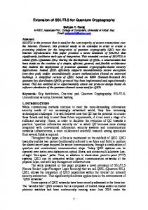
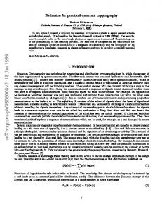
FIG. 1. Sagnac interferometer with a PBS, which implements a controlled operation from polarization to transverse modes. The Dove prism applies a rotation to the transverse wavefront distribution, being the sign of this rotation determined by the direction of propagation.
Finally, to complete the set of operations we propose to implement the controlled operation using a Sagnac-type interferometer with a Polarization Beam Splitter (PBS) (Fig. 1), based on the study of momentum and polarization entanglement reported by Fiorentino et al. [16]. This is a robust implementation because there is no need for dynamical compensation of the optical path, being the Sagnac a common-path interferometer. In this setup, by means of a Dove prism which is rotated along the propagation axis (a π-converter), the transverse modes can be rotated by an angle whose sign depends on the direction of propagation. In turn, as a consequence of the presence of the PBS, each polarization component travels through the interferometer in different directions. Then, the device transforms each polarization in a different way. If the Dove prism is positioned as in figure 1, neither the polarization nor the transverse modes are affected, implementing the identity operator. However, if the prism is rotated at an angle of π/8, an U operator is applied to the TM qubit for the component that travels in one
3 Output A
direction and the U † is applied to the other (1). Therefore, the change of basis of the TM qubit is controlled by the polarization qubit and can be switched on/off by choosing the Dove prism angle. x
Sagnac
�π� 8
y
: •
| / i U
U†
(1)
Combining the previous operations we can change basis from the computational one to any other basis in the Hilbert space. Using the UPR and UTR we build any local transformation. Combining them with the controlled operation, we can prepare any state starting from the computational basis. This also enables measurement on any basis since we can first rotate to the computational one and then perform a projective measurement on the canonical basis.
III.
PROJECTION ON THE CANONICAL BASIS
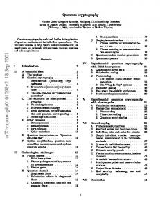
For the polarization qubit the projective measurement onto the computational basis can be easily performed using a PBS. This separates the paths of the | i and | i components of the incoming state. Then, they can be separately detected with single photon detectors. This simple optical element implements the measurement onto the Z ⊗ I basis of the polarization qubit. The measurement onto the eigenstates of the Z basis associated with the TM qubit can be performed with the same idea. We simply need a TM beam splitter that splits up the beam into its | i and | i components. This can be implemented using a Mach-Zehnder interferometer with an Extra Mirror as shown in Fig. 2, as proposed by Sasada et al. [17]. Such interferometer works by exploiting the symmetry (anti-symmetry) of modes | i (| i) against specular reflection along the yˆ axis. On each output mode of the MZEM there is interference between the incoming wavefront and its mirror reflection. Because of the extra mirror there is an additional phase and the system is therefore selective to states with vertical symmetry. Thus, interference is constructive on one output while it is destructive in the other one, depending on the parity of the input state. A phase plate inserted in one of the arms of the MZEM allows for additional control over the interference condition at the outputs, as in a standard amplitude division interferometer. The two states {| i,| i} have different parity. As the MZEM applies the operator Z ⊗ Z, the output depends on the TM state and on the polarization state of the incoming photon. The correct identification of the projected TM qubit strongly depends on the optical path difference between the arms of the interferometer. Subwavelength stability is necessary and, as a consequence
BS
| / i
� � 1 1 1 U= √ 2 −1 1
Output B
z
Phase Control
FIG. 2. Mach-Zehnder interferometer with an Extra Mirror, that can discriminate | i and | i states. The states with symmetry against specular reflection along the yˆ axis remain invariant after mirror reflections, and the states with antisymmetry get a π phase. The superposition on the MZEE output generates destructive and constructive interference on the complementary exits for sates with different parity eigenvalues.
the MZEM requires dynamic optical path stabilization. Taking this into account, the different TM modes can be discriminated with the above device. Using the projective measurement onto the Z ⊗ Z and the Z ⊗I basis, any state of the full 4D computational basis can be identified (since each one of them corresponds to one of the four different pairs of measured eigenvalues). We will use this measurement scheme in the 4D QKD method, which is described in the following two sections.
IV.
EXTENDED QKD WITH POLARIZATION AND TRANSVERSE MODES
The protocol we present here is an extension of the BB84 protocol [3] for a larger 4D Hilbert space. For this we use two or more mutually unbiased bases to encode and measure two bits. In the next subsection we describe this 4D QKD procedure in abstract terms and in the following section we describe the actual procedure for implementing it using the polarization and TM states of a single photon.
A.
The general QKD protocol for two qubits
The protocol is as follows: Alice encodes two random bits by choosing one of the four states of a basis which is chosen at random from a set of five mutually unbiased bases. She sends the state to Bob who performs a projective measurement on a basis which is randomly chosen from the same set of MUB’s. After repeating this round of quantum communication many times, they publicly announce the sequence of bases they used. When the basis chosen by Alice and Bob coincide they get a shared pair of random bits. With this in hand, they can distill a
4
Basis B1 B2 B3 B4 B5
ZZ XX YY YX XY
CSCO , ZI , IZ , XI , IX , Y I , IY , XZ , ZY , Y Z , ZX
Table II. Bases names and the Complete Set of Commuting Operators that define them, expressed as tensor products between Pauli matrices and the identity operator I. B1 is the Canonical basis. B4 and B5 are the entangled bases.
B.
Physical implementation with two qubits per photon
The toolbox we presented above enables the manipulation and measurement in the full 4D space of states of
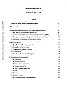
the two qubits encoded in a single photon. This can be used to implement the 4D QKD protocol we described in the previous section. Thus, we implement this scheme by encoding two qubits on polarization and TM of a single photon. For this purpose Alice has to prepare an arbitrary state from any of the D + 1 = 5 mutually unbiased basis. This is done by using an experimental setup as the one shown in Fig. 3. The input state is | i from the basis B2. State preparation is separated in two parts: The first one consists in the basis choice and the second step involves the choice of a state within the chosen basis. Therefore, Alice first chooses whether to prepare a state either from the entangled or the product bases sets. For any state within the product basis set she must switch off the the controlled operation, which conversely it must be turned on if the chosen state corresponds to the entangled set. Then she decides which basis is finally chosen within the selected set by applying single-qubit operations. Also, with single-qubit operations she defines which of the four states of the basis is prepared. The detailed description of the state preparation is expressed as sequences of operators in the Appendix A.
Alice Dove prism x
y
z
PB S
secure sequence of random bits using classical algorithms for error correction [18] and privacy amplification [19]. If an intruder, Eve, tries to steal information from the key, she would have to perform measurements on a randomly chosen basis and resend the quantum state to Bob. This would generate distortions on the correlations between Alice and Bob. Thus, Alice and Bob can detect these distortions and ensure the privacy of the key with privacy amplification algorithms. Such task can be done only if the quantum bit error rate induced by Eve’s attack is not greater than a critical value of tolerance. This value depends on the dimension of the Hilbert space, on the number of bases used on the protocol and on the kind of attacks Eve can perform. This has been studied in previous works based on the BB84 protocol [20] and also for extended protocols [5]. By encoding several qubits on a single photon it could be possible to enhance the level of tolerance for the quantum bit error rate, using only two mutually unbiased bases to encode the bits (these two bases can be selected from any maximal set of five mutually unbiased bases that can be build for a 4D Hilbert space [21]). If the entire set of five mutually unbiased bases is used, the tolerance to errors can be further increased by a small amount [5]. It is worth mentioning that there is a tradeoff between this improvement in security with five MUBs and the increase in the rate of key bit generation that is maximal when one uses only two basis, as was noted in [4]. There is an infinite number of sets of five mutually unbiased bases that can be chosen to implement the above protocol. However, there are sets which are particularly simple as they arise as eigenstates of commuting sets of generalized Pauli operators. One can always choose a set of three basis which are separable. In fact, they are formed by the eigenstates of X, Y and Z for each individual qubit. To get the D+1=5 mutually unbiased basis one needs to add two bases formed with entangled states. Out of the many possibilities to define these bases, here we will choose the set of the Table II.
UPR
UTR FIG. 3. Scheme of Alice’s setup to prepare a general state using single-qubit operations for each qubit (UPR and UTR) and a controlled operation implemented with the Sagnac interferometer and a Dove prism.
At the other end, Bob must perform a projective measurement onto any of the possible bases. For this he has to apply the inverse procedure used by Alice to prepare the corresponding basis. In this way he would map the chosen basis onto the basis B2. This basis must be further rotated to B1, the computational basis, using a HWP and a π-converter. Finally, to detect a single state within this basis he must use a MZEM, two PBS’s and 4 different photon detectors. In this way he completes the projective measurement (Fig. 4). For a correct implementation of the protocol, the optical alignment of all the optical elements must be finetuned. This is not straightforward because the overall
x
UTR
basis selection
Dove prism
C
UPR
HWP
z
Bob
BS
y
canonical basis projection
5
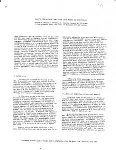
FIG. 4. Scheme of Bob’s setup, with which any basis projection can be obtained. The “basis selection” part consists on a copy of reversed copy of Alice’s setup and an extra πconverter, which can map any basis onto the canonical one. The “canonical basis projection” part consists on the combination of a TM discriminator (MZEM), two polarization discriminators (PBS) and four single-photon detectors that implement a projective measurement of the canonical basis.
efficiency of the method is limited by factors such as: the correct mode-matching at the cylindrical lenses, the losses imposed by reflections on optical surfaces and the efficiency of qubit discrimination. Off-the-shelf PBS with low losses and high extinction ratios for a defined wavelength can be used, but the efficiency of the MZEM depends on several other factors that will be analyzed in the next section.
V.
TM BEAMSPLITTER TEST
We built and tested a MZEM to evaluate the feasibility of using TM of light as qubits using the above scheme. We were able to generate and discriminate all the canonical basis states using the proposed device. The results we present here are similar to those recently reported by Sasada et al. [17] for the case of intense light beams. However, here we show the performance of the method to discriminate TM on the single-photon limit, which is essential for a QKD protocol. In what follows we describe the setup and the techniques we used to obtain good visibility on the interferometer, which is a mandatory condition to realize QKD. The efficiency of the MZEM strongly depends on the quality of the TM. As described above, a different interference pattern is produced depending on the properties of the modes under reflection in the mirror. Then, the device is very sensitive to defects on the reflection symmetry of the transverse intensity profile. It is also very sensitive to the preservation of the symmetry or antisymmetry of the phase distribution. Thus, the initial TM state preparation has to be done carefully in order to control these features. The photon source was built from a CW diodepumped, intracavity doubled Nd-YAG laser, using a
BBO crystal which was cut for type-II phase-matching condition. This system emits a few milliwatts of a 532 nm beam with an effective coherence length of 5 mm. The TM modes were built generating a π phase change over half of the wavefront using a thin glass plate. The resulting beam was spatially filtered and collimated. An iris diaphragm was used to control the spot size and a Dove prism allowed for rotation of the transverse pattern around the propagation direction (Fig. 5), in order to select the transverse-mode state of the canonical basis. Finally, the polarization state was selected with a PBS. When needed, the beam was attenuated with neutral density filters and a Malus-like device to achieve the single photon regime. Spatial Filter
Iris
Dove Prism
Pin Hole
Phase plate
+
_
+
_
FIG. 5. Scheme of the TEM builder used to test the MZEM. The lower part shows a simplified picture of the beam profile obtained at different stages of the process
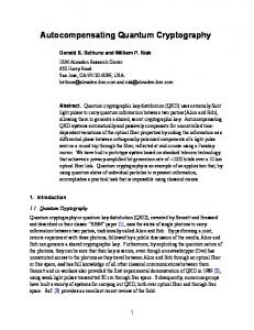
Construction of the MZEM requires a more careful alignment than a standard Mach-Zehnder interferometer. One key issue is the double mirror reflection, that introduces an additional optical path on one of the arms that has to be compensated on the other one. The position of the single mirror (Fig 2) was estimated by simple geometric calculations. The fine tuning of the path compensation was realized by mounting the double mirror assembly on a micrometer-driven translation stage and scanning it along its symmetry axis, exploiting geometrical properties of the design (Fig. 6). An auxiliary laser source with 0.1 mm coherence length was used to find the optimal position of the double mirror position to reduce the path difference below 0.1 mm, achieving optimal visibility for TEM00 modes. The optical path was actively compensated during measurements using a He-Ne laser aligned collinear with the photon source path and vertically displaced from it. The temporal behavior of the He-Ne interference pattern was registered with a photodiode and used as source of a feedback circuit to correct the position of a single mirror mounted over a piezoelectric actuator, thus locking the optical path difference with an estimated accuracy of 10 nm. The MZEM was tested for the four states of the canonical basis, both on an intense beam regime and on a weak beam regime, i.e. the single photon regime. Table III
6 Output A 45°
F
22.5°
F
Output B
F
F Δd y
F
F
z
x
F
F x
y
F
F z
BS
ΔOP=Δd·√2
FIG. 6. The geometrical properties of the double mirror enables to generate a change over the optical path length. A displacement of ∆d over the symmetry axis produces a differ√ ence of 2 ∆d on the optical path.
shows the high intensity transverse modes at the output of the MZEM for the canonical basis states, registered with a CCD camera and colored by intensity. A particularly sound demonstration of the MZEM operation is the decomposition of a diagonal state in its canonical components (fourth row of Table III). Also, the PBS-like behavior described in [17] was confirmed. The performance was also tested at the single photon regime, using a strongly attenuated beam and detecting individual photons with a set of PhotoMultiplier Tubes (PMTs) Hamamatsu H5783P. The intensity was adjusted to achieve a count rate that guarantees a photon rate lower than one photon per transit time at the MZEM, as a condition for a single photon regime. PMTs were selected over Avalanche Photodiodes because they have a larger detection area that enables the collection of the entire spot of the spatial modes of light. For the single photon regime, the interference visibility over both outputs of the MZEM was measured for each state of the canonical basis using photon counting. The results (Table IV) show a visibility of V ≈ 0.9, which is sufficient to perform a proof-of-concept demonstration of a 4D QKD protocol. The visibility at the output A (Fig. 7) is slightly lower because of imperfect BS splitting ratio at the working wavelength. The visibility of vertical TM qubits is considerably lower because of an inherent characteristic of the MZEM alignment: the interferometer is extremely sensitive to lateral displacements of the incident beam, as depicted in figure 7, thus producing a separation over the output beams and deteriorating the interference pattern. This feature is particularly detrimental for states that lack vertical symmetry on the intensity profile. These difficulties can nevertheless be controlled by careful alignment to achieve good and stable visibility with no fundamental limitations.
FIG. 7. Geometry considerations for the beam propagation on the MZEM. In contrast to a normal Mach-Zehnder, a lateral shift on the incident beam produces a relative displacement of the two beams at the input of the second beamsplitter, which limits the interference effect to the overlap area between the two displaced beams. On the scheme, an aligned (green) and a displaced (doted red/orange) beam are shown. The F symbol depicts the transformation of the transverse intensity pattern of each beam by the mirror reflections.
VI.
CONCLUSIONS
We presented a toolbox for the implementation of a QKD protocol in a four dimensional Hilbert space. In particular, we studied in detail the potential application of this protocol using the two qubits that can be stored in a single photon using the polarization and TM degrees of freedom. The scheme we presented enables us to perform each step of the QKD protocol, with complexity that depends on the operation that is to be performed. As any involved free-space optical setup, the complete alignment of both Alice and Bob stages is not trivial. The use of cylindrical lenses in the UTR stage requires a careful mode matching of the incoming beam (and a careful alignment of cylindrical systems is a complex and troublesome task). The operation of the UPRs can be made very fast by using Polarization Controllers, or combinations of several Pockels Cells. Refractive lenses limit the speed of implementation of a UTR, although spatial light modulators used as Fresnel lenses appear as an alternative that can enable fast switching. The MZEM accuracy depends strongly on active stabilization of the optical paths. However, this issue can be easily hurdled with standard stabilization techniques. The MZEM is also specially sensitive to x ˆ displacements from the optimal transverse position. In contrast, the Sagnac interferometer is very robust and practically insensitive to mid- and long term fluctuatios produced by thermal and mechanical stress. The qubit implementation on the transverse electromagnetic modes of a light beam increases the capacity of single photons to carry quantum information, and appears as an alternative to other degrees of freedom such as the linear momentum, or path. The presented scheme can be used as a proof-of-concept demonstration of a 4D
7 A
B
red (dotted)
Path blue (straight)
φ=0
Interference φ=π
| i| i Output A
| i| i Output B
| i| i Output A
| i| i Output B
Table III. Recorded intensity profiles of different states from the Canonical basis, obtained at the A and B MZEM outputs. On each row, the input is the 2-qubit state at the left. The first two columns correspond to the output beam profiles when one or the other interferometer arms are blocked. The last two columns show the interference patterns for two different (complementary) phase conditions. φ is the relative phase between the two interferometer arms.
| , i | , i | , i | , i Output A 95 ± 8 91 ± 13 65 ± 12 68 ± 9 Output B 98 ± 7 95 ± 12 83 ± 18 75 ± 16
for the photon polarization-transverse modes qubits may clear the way to perform other original experiments on quantum information.
Table IV. Visibility (%) of each exit measured for every input state of the canonical basis on the single photon regime. VII.
ACKNOWLEDGEMENTS
QKD protocol with 2 qubits encoded on each photon. The use of TM in combination with polarization modes can be also used for alignment-free quantum communication protocols [22]; furthermore the ability to prepare and project any state of any of the 5 Mutually Unbiased Bases
This work was supported through ANPCyT, CONICET and UBACYT grants. C.T.S. was funded by a CONICET scolarship. M.A.L. and J.P.P. are fellows of CONICET.
[1] W. K. Wootters and W. H. Zurek. A single quantum cannot be cloned. Nature, 299(5886):802–803, October 1982. doi:10.1038/299802a0. URL http://dx.doi.org/ 10.1038/299802a0. [2] Michel Planat, Haret C Rosu, and Serge Perrine. A survey of finite algebraic geometrical structures underlying mutually unbiased quantum measurements. Foundations of Physics, 36(11):1662–1680, 2006. [3] Charles H. Bennett and Gilles Brassard. Quantum cryptography : Public key distribution and coin tossing. Theoretical Computer Science, September 2011. ISSN 03043975. doi:10.1016/j.tcs.2011.08.039. URL http: //dx.doi.org/10.1016/j.tcs.2011.08.039. [4] William T. Buttler, Steven K. Lamoreaux, and Justin R. Torgerson. Practical four-dimensional quantum key distribution without entanglement. Quantum Info.
Comput., 12(1-2):1–8, January 2012. ISSN 15337146. URL http://dl.acm.org/citation.cfm?id= 2231036.2231037. [5] Nicolas J. Cerf, Mohamed Bourennane, Anders Karlsson, and Nicolas Gisin. Security of quantum key distribution using d -level systems. Phys. Rev. Lett., 88:127902, Mar 2002. doi:10.1103/PhysRevLett.88.127902. URL http://link.aps.org/doi/10.1103/PhysRevLett.88. 127902. [6] Michael A. Nielsen and Isaac L. Chuang. Quantum Computation and Quantum Information. Cambridge University Press, 1 edition, October 2004. ISBN 0521635039. URL http://www.amazon.com/exec/obidos/redirect? tag=citeulike07-20&path=ASIN/0521635039. [7] B. Neethi Simon, C. M. Chandrashekar, and Sudhavathani Simon. Hamilton’s turns as a
8
[8]
[9]
[10]
[11]
[12]
[13]
[14]
[15]
[16]
visual tool kit for designing single-qubit unitary gates. Phys. Rev. A, 85:022323, Feb 2012. doi:10.1103/PhysRevA.85.022323. URL http: //link.aps.org/doi/10.1103/PhysRevA.85.022323. Berthold-Georg Englert, Christian Kurtsiefer, and Harald Weinfurter. Universal unitary gate for single-photon two-qubit states. Phys. Rev. A, 63:032303, Feb 2001. doi: 10.1103/PhysRevA.63.032303. URL http://link.aps. org/doi/10.1103/PhysRevA.63.032303. L. Allen, M. W. Beijersbergen, R. J. C. Spreeuw, and J. P. Woerdman. Orbital angular momentum of light and the transformation of laguerre-gaussian laser modes. Phys. Rev. A, 45:8185–8189, Jun 1992. doi: 10.1103/PhysRevA.45.8185. URL http://link.aps. org/doi/10.1103/PhysRevA.45.8185. M.W. Beijersbergen, L. Allen, H.E.L.O. van der Veen, and J.P. Woerdman. Astigmatic laser mode converters and transfer of orbital angular momentum. Optics Communications, 96(13):123 – 132, 1993. doi:10.1016/00304018(93)90535-D. URL http://www.sciencedirect. com/science/article/pii/003040189390535D. S.J. van Enk and G. Nienhuis. Eigenfunction description of laser beams and orbital angular momentum of light. Optics Communications, 94(13):147 – 158, 1992. ISSN 0030-4018. doi:10.1016/0030-4018(92)90424P. URL http://www.sciencedirect.com/science/ article/pii/003040189290424P. S. J. van Enk and G. Nienhuis. Spin and orbital angular momentum of photons. EPL (Europhysics Letters), 25(7):497, 1994. URL http://stacks.iop.org/ 0295-5075/25/i=7/a=004. E. Abramochkin and V. Volostnikov. Beam transformations and nontransformed beams. Optics Communications, 83(12):123 – 135, 1991. ISSN 0030-4018. doi:http://dx.doi.org/10.1016/0030-4018(91)90534K. URL http://www.sciencedirect.com/science/ article/pii/003040189190534K. Jonathan Leach, Miles J. Padgett, Stephen M. Barnett, Sonja Franke-Arnold, and Johannes Courtial. Measuring the orbital angular momentum of a single photon. Phys. Rev. Lett., 88:257901, Jun 2002. doi: 10.1103/PhysRevLett.88.257901. URL http://link. aps.org/doi/10.1103/PhysRevLett.88.257901. M. J. Padgett and J. Courtial. Poincar´e-sphere equivalent for light beams containing orbital angular momentum. Opt. Lett., 24(7):430–432, Apr 1999. doi:10.1364/OL.24.000430. URL http://ol.osa.org/ abstract.cfm?URI=ol-24-7-430. Marco Fiorentino and Franco N. C. Wong. Deterministic controlled-not gate for single-photon two-qubit quantum logic. Phys. Rev. Lett., 93:070502, Aug 2004. doi: 10.1103/PhysRevLett.93.070502. URL http://link.
aps.org/doi/10.1103/PhysRevLett.93.070502. [17] Hiroyuki Sasada and Megumi Okamoto. Transversemode beam splitter of a light beam and its application to quantum cryptography. Phys. Rev. A, 68:012323, Jul 2003. doi:10.1103/PhysRevA.68.012323. URL http: //link.aps.org/doi/10.1103/PhysRevA.68.012323. [18] Gilles Brassard and Louis Salvail. Secret-key reconciliation by public discussion. In Tor Helleseth, editor, Advances in Cryptology EUROCRYPT 93, volume 765 of Lecture Notes in Computer Science, pages 410–423. Springer Berlin Heidelberg, 1994. ISBN 978-3-540-576006. doi:10.1007/3-540-48285-7˙35. URL http://dx.doi. org/10.1007/3-540-48285-7_35. [19] C.H. Bennett, G. Brassard, C. Crepeau, and U.M. Maurer. Generalized privacy amplification. Information Theory, IEEE Transactions on, 41(6):1915–1923, 1995. ISSN 0018-9448. doi:10.1109/18.476316. [20] Christopher A. Fuchs, Nicolas Gisin, Robert B. Griffiths, Chi-Sheng Niu, and Asher Peres. Optimal eavesdropping in quantum cryptography. i. information bound and optimal strategy. Phys. Rev. A, 56:1163–1172, Aug 1997. doi:10.1103/PhysRevA.56.1163. URL http://link.aps. org/doi/10.1103/PhysRevA.56.1163. [21] Bandyopadhyay, Boykin, Roychowdhury, and Vatan. A new proof for the existence of mutually unbiased bases. Algorithmica, 34:512–528, 2002. ISSN 0178-4617. doi: 10.1007/s00453-002-0980-7. URL http://dx.doi.org/ 10.1007/s00453-002-0980-7. [22] L. Aolita and S. P. Walborn. Quantum communication without alignment using multiple-qubit single-photon states. Phys. Rev. Lett., 98:100501, Mar 2007. doi: 10.1103/PhysRevLett.98.100501. URL http://link. aps.org/doi/10.1103/PhysRevLett.98.100501.
Appendix A: State preparation
The first column of Table V shows the operations Alice must implement for every basis selection, starting from the state | i| i. The second column shows the operations that Alice must perform to select which state from that basis is prepared. Bob can use the reversed circuit of column one to implement the conversion of any basis to the B2 basis. All the local gates can be combined as a unique rotation on the Bloch sphere; this can be implemented with the UPR and the UTR on the respective qubits. The action of the Sagnac Controlled Operation consists in setting the angle of the Dove prism on π/8, and it can be disabled by setting the angle to zero.
9 Basis selection operation circuit
State selection
Prepared state
B1 | i
Had
| i
|
Had
| i
i
I ⊗I I ⊗ MCπ (π/4) H(π/4) ⊗ I H(π/4) ⊗ MCπ (π/4)
| | | |
, , , ,
i i i i
| | | |
, , , ,
i i i i
| | | |
, , , ,
i i i i
B2 | i
I
| i
|
I
|
i
I ⊗I I ⊗ MCπ (0) H(0) ⊗ I H(0) ⊗ MCπ (0)
i
B3 | i
S
| i
|
S
| i
i
I ⊗I I ⊗ MCπ (0) H(0) ⊗ I H(0) ⊗ MCπ (0) B4
| i Sagnac |
i
Had
S
I ⊗I I ⊗ MCπ (0) H(0) ⊗ I H(0) ⊗ MCπ (0)
√1 ( 2 √1 ( 2 √1 ( 2 √1 ( 2
| | | |
, , , ,
i+| i+| i−| i−|
, , , ,
i) i) i) i)
1 √ ( 2 1 √ ( 2 1 √ ( 2 1 √ ( 2
| | | |
, , , ,
i+| i−| i+| i−|
, , , ,
i) i) i) i)
B5 | i
S Sagnac
|
i
Had
I ⊗I I ⊗ MCπ (0) H(0) ⊗ I H(0) ⊗ MCπ (0)
Table V. State preparation procedure. The first column shows the algorithm applied by Alice to select a particular basis, starting always from the state | i | i of B2. The product bases only need single qubit gates such as the Hadamard (Had), the Phase gate (S) or the Identity (I), which can be implemented by the UPR and UTR. The controlled operation build with the Sagnac interferometer is also needed to produce the entangled bases. Bob can reverse this algorithm to convert any basis to B2. The second column shows the specific single qubit operations that must be performed by Alice after the basis selection to prepare each of the four states. The H(α) and MCπ (α) operators accounts for a HWP and a TM π-converter respectively, rotated by an angle of α. The single qubits operators of the basis selection stage and the final state definition stage can be combined in a unique rotation of the Bloch sphere implemented by the UPR and UTR.