MANUFACTURING DATA VALIDATION THROUGH SIMULATION Guodong Shao Y. Tina Lee Charles McLean Manufacturing Simulation and Modeling Group National Institute of Standards and Technology (NIST) 100 Bureau Drive, MS 8260 Gaithersburg, Maryland 20899, U.S.A. E-mail:
[email protected]
KEYWORDS Computer Aided Manufacturing Engineering (CAME), Data Validation, Numerical Control program, Manufacturing Simulation. ABSTRACT In order to ensure that the process plan and numerical control (NC) programs are complete and correct before jobs are released to the shop floor, manufacturing industry needs a validation system that has visualization and analysis capabilities. A prototype manufacturing data validation system has been developed by the Manufacturing Simulation and Modeling Group of the National Institute of Standards and Technology (NIST). The work was carried out as a part of the NIST/NAVY Computer Aided Manufacturing Engineering (CAME) program. The manufacturing data validation system uses simulation and an interactive checklist to validate the manufacturing engineering data package. This paper discusses the manufacturing data validation methodology through a simulation model and presents a prototype of a manufacturing data validation system. DISCLAIMER No approval or endorsement of any commercial product by the National Institute of Standards and Technology is intended or implied. Centain commercial software systems are identified in this paper in order to facilitate understanding. Such identification does not imply that these software systems are necessarily the best available for the purpose. INTRODUCTION In order to ensure that the process plan and NC program are complete and correct before jobs are released to the shop floor, manufacturing industry needs a validation system that has visualization and analysis capabilities. The manufacturing data validation system uses simulation and an interactive checklist to validate the manufacturing engineering data package. A manufacturing engineering data package is a set of information necessary for supporting manufacturing operations and resources to produce a part or batch of parts.
A data package may include the following types of documents: • Part specifications and drawings • Routings and operation sheets • NC programs • Tool and fixture lists • Setup instructions and illustrations • Material lists • Quality control data The degree of accuracy of these manufacturing data is directly related to the quality and cost of the product; therefore, manufacturing engineering data validation is a critical step in production process. Manufacturing engineering data packages often contain errors that may result in inefficient use of production resources. The erroneous data must be corrected prior to the first production run. Individual data packages and associated production processes need to be checked prior to production startup. For example, an NC program, a part of the manufacturing data, should be validated. An NC program contains a set of instructions; those are the sequences of machining operations on the workpiece. Traditionally, once an NC program is generated, it was validated by checking the NC tool path plots or performing dry run on a real machine. These traditional validation methods may not be reliable and could be labor intensive, dangerous and costly. Some undetectable errors may remain in the NC program. Those undetected errors may result in poor part quality, premature tool wear out, or tool breakage. A manufacturing data validation process is therefore recommended. Based on the set of requirements identified for the manufacturing data validation system (Leong and Smith 1995), Delmia’s Virtual Numerical Control (VNC), version 4.1 was selected as the development tool for the prototype of the manufacturing data validation system. IMPLEMENTATION METHODOLOGIES The primary function of the data validation system is to validate manufacturing process data in a virtual manufacturing environment that emulates a physical manufacturing system. The steps of this validation process include: • Control and management of the validation process • Creation of the validation environment
• • • • • • • •
Validation of data availability Validation of data integrity Validation of process capability Validation of process performance Validation of machining parameter Detection of collision Identification of force and thermal effects Evaluation of geometry and tolerances
Data validation methodology The data validation system ensures the part will be produced correctly the first time. The data validation can be performed manually or automatically. The elements of validation are described as follows (McLean et al. 1995): • Data availability: Check whether all the required documents exist in the manufacturing data package • Data integrity: Check whether all documents have the proper structure and information contents • Resource availability: Check whether all the required manufacturing resources exist for the assigned tasks • Process capability: Check whether the selected resources and processes are capable of achieving the required results without causing any undesirable side effects • Process performance: Check whether the planned production process achieve quality, time, and cost objectives
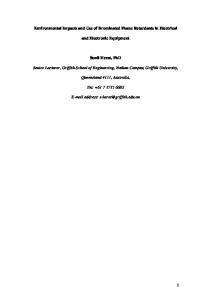
A prototype validation system has been developed using the validation methodology. The primary function of the prototype validation system is to simulate machining operations and execute validation procedures as the operation is being executed. The purpose is to assess the feasibility of implementing the validation concept in the simulation environment. The system, shown in Figure 1, is a simulation model for machining center MAKINO A55 (Delmia 1996). The simulation model incorporates the advantages of program tryout on the actual machine tool, with the ease and speed of computer simulation. Through the emulation of the entire machine tool and Computer Numerical Control (CNC) controller, the prototype model provides the manufacturing data validation system with following list of capabilities: • Validate and debug the NC program on a virtual manufacturing environment • Verify tooling and fixture setups • Evaluate the post processor and virtual machine models • Validate and optimize the process and create final manufacturing documentation
NC program validation methodology The NC program validation verifies the NC program generated by the process planning system. The NC program is the code used to produce the designed part on a specific machine using selected resources. The validation code is implemented as a work element. NC programs are validated in the machine tool simulation model. The NC program validation ensures: • Correct media and version • Cutting operations within proper process envelope • Rigidity of setup, tools, etc. • No collisions • Correct part geometry produced Before the start of the NC program validation, the following validation procedures need to be performed. • Operation plan validation • Machine loading procedure validation • Workpiece loading procedure validation • Machine operation procedure validation The validation procedures are grouped into several functional program units. These program units are sets of subroutines. Wherever possible, standard system, database, or other library routines should be used to implement these functional units. A PROTOTYPE VALIDATION SYSTEM
Figures 1: Prototype of the Validation System - MAKINO A55 Model In the prototype validation system environment, the following virtual system elements are developed: • A simulated work cell model of high-speed machining center (Makino A55) • Models of a tool set for the selected test part • Workpiece models for test part • Fixture component models • A set of validation procedures • An Oracle database • Reference data (includes cutting speed table, feed rate table, specific energy table, tool table, spindle power specification given in the machine tool reference manual) The inputs of the data validation system are: • NC programs generated by the process planning system • Process planning data The outputs of the validation system are:
• • • • •
The prototype is focused on milling operations used in the Makino A55 machining center. The checklists are currently limited to high-speed steel and carbide cutting tools, and the parts material are aluminum, titanium, and a few other types. In the process of the data validation, some of the required information can be directly obtained. Table 1 lists the method to retrieve the information.
Validated NC programs Validation reports Warning messages Error messages Finished virtual products
Validation and Simulation System Architecture The validation and simulation system architecture is shown in Figure 2. Some validation procedures, such as collision control, can be set up in the simulation environment. However, most of the procedures are programmed inside the system control program, a Delmia Mimic program. The procedures are logically related groups of software subroutines.
Table 1: Data items and Description of the Required Information Data item Tool specifications
VNC simulation environment
Workcell
NC code
Tool
Machine
Depth of cut
Fixture
Workpiece
Other devices
Width of cut
MIMIC Controller
Validation Procedure 1
Validation Procedure 2
Validation Procedure 3
Validation Procedure 4
......
Validation Procedure n
Linear feed rate
Figures 2: Validation and Simulation Subsystem Architecture NC Program Validation Procedure
Spindle speed
In order to validate the NC program, it needs to be loaded into the virtual machine model, the simulation needs to be started, the validation program will parse, and run the NC statements one by one. The NC statements contain data necessary for the cutting operation such as miscellaneous functions (M codes), rapid motion (G00), or machining operations (G01, G02 and G03), as well as cutting attributes as follows: • Depth of cut • Width of cut • Linear feed rate • Spindle speed • Tool identification • Tool material type • Tool diameter • Tool length • Number of cutting edges
Material removal rate
Related information needs to be retrieved from the NC statement and recommended ranges need to be computed, and then checked to ensure that they are within the ranges. If any of the data is out of the recommended range, an error report needs to be generated, and at the same time, a screen message is also displayed. Required information.
Recommended machining parameters
Description Based on the unique tool id listed in the NC program, the cutting tool material, tool diameter (D), tool length (L) and the number of cutting edges can be obtained from the tool database. VNC continuously provides the depth of cut of each NC statement. In milling operation, the width of cut can be either the difference of two X’s or Y’s values depending on machining axis. Linear feed rate (F) can be obtained from the NC statement. It is valid for subsequent NC statements until a new value is listed. Spindle speed (S) can be obtained from NC statement. VNC provides function to obtain the material removal rate. Recommended machining parameters such as cutting speed, feed rate per cutting edge, or specific energy can be obtained from reference books.
Computation of the machining parameters For the information that cannot be retrieved directly from the system or NC statements, computations are needed. Also in order to ensure those recommended values are consistent with the unit of measure given in the NC program, unit conversion/computation is often performed. These computations include: converting cutting speed (V) to spindle speed (S), computing linear feed rate (F), and spindle power (Nm) (Serope 1995). Checklist of the validation for an NC Statement The NC statement validation will ensure the data and data syntax are correct, complete, and collision free when the machine is in rapid motion. It also ensures the machine parameters are within specification limits. NC program’s validation checklist is listed as follow:
•
•
•
M code: The validation ensures that necessary miscellaneous functions, such as coolant on, coolant off, and spindle on, are in the right positions. Table 2 presents the miscellaneous functions checklist items and description. Potential collision in rapid motion mode: When the machine is executing G00, cutting tool is at maximum feed rate. There is no machining operation that occurs during the movements. Therefore, there should not be any contacts between cutting tool with the machine, workpiece, and fixtures. Machining functions: G01, G02, G03, and canned cycles (G81 to G89) are machining cycles. There are several machining parameters associate with these cycles such as spindle speed, linear feed rate, spindle power, maximum depth of cut as listed in Table 3, and maximum step-over depth of the cut. This validation ensures that these machining parameters are within the specification’s ranges. Table 2: Miscellaneous Functions Checklist Items and Description Item Spindle starts (M03/M04)
Coolant on (M08)
Unlock rotary table (M11)
Lock rotary table (M10)
Description Spindle should be turned on only after a tool has been moved to a desired position. Coolant should be turned on only after spindle has been turned on in order not to block operator’s view while the spindle is moving to its desired position. Table needs to be unlocked before it rotates to avoid damaging the machine, NC statement may command to rotate the table even when the table is in a locked position. For accuracy purposes, rotary table needs to be locked in the position after it has been rotated to a desired position.
Table 3 Machining Parameters Checklist Items and Description Item Spindle speed
Linear feed rate
Spindle power
Description Check if the value is within the recommendation range, spindle speed affects cutting tool’s life. Check if the value given in NC program is within calculated range. Check if the value given in NC program is within the
Depth of cut
Maximum stepover of Cut
machine specification. Check if the depth of cut is within zero to 0.8 of cutting length interval (0