ACTIVE NOISE CONTROL AT HIGH FREQUENCIES Erkan Kaymak*1, Mark Atherton1, Ken Rotter2, Brian Millar3 1
Applied Mechanics Group, School of Engineering and Design, Brunel University Kingston Lane, UB8 3PH London, UK 2 Department of Engineering Systems, London South Bank University 103 Borough Road, SE1 0AA London, UK 3 King’s College London Dental Institute at Guy’s, King’s & St Thomas’ Hospitals Caldecot Road, SE5 9RW London, UK *
[email protected]
Abstract There are many applications that can benefit from Active Noise Control (ANC) such as in aircraft cabins and air conditioning ducts, i.e. in situations where technology interferes with human hearing in a harmful way or disrupts communication. Headsets with analogue ANC circuits have been used in the armed forces for attenuating frequencies below 1 kHz, which when combined with passive filtering offers protection across the whole frequency range of human hearing. A dental surgery is also a noisy environment; in which dental drill noise is commonly off-putting for many patients and is believed to harm the dentist’s hearing over a long period of time. However, dealing with dental drill noise is a different proposition from the applications mentioned above as the frequency range of the peak amplitudes goes from approximately 1.5 kHz to 12 kHz, whereas conventional ANC applications consider a maximum of 1.5 kHz. This paper will review the application of ANC at low frequencies and justify an approach for dealing with dental noise using digital technologies at higher frequencies. The limits of current ANC technologies will be highlighted and the means of improving performance for this dental application will be explored. In particular, technicalities of implementing filtering algorithms on a Digital Signal Processor will be addressed.
INTRODUCTION Background to ANC One of the first applications of Active Noise Control (ANC) was made by H.F. Olsen in the 1950s [13]. It provided very limited noise attenuation due to limited frequency range and instability due to its non-adaptive feedback control. But over the past 20 years the field has developed encouraged by developments in signal processing technology. Although applications of ANC in consumer products are still rare, a huge research community is focused on ANC and also Active Vibration Control (AVC). Developments over the early period focused on the fundamental physical constraints. For example Nelson et al [12] have developed the theory that global sound reduction, where the sound in the entire enclosure is attenuated, is dependent on the distance
E. Kaymak, M. Atherton, K. Rotter and B. Millar
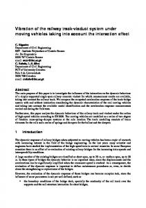
between the primary source (noise source) and the secondary source (loudspeaker producing the anti noise) such that it has to be less than one tenth of the wavelength to produce 10 dB global sound reduction. The theory was verified through simulations and experiments by Bullmore and Elliott [2,4] and since then ANC has only been applied to low frequency problems and there are no further results towards higher frequencies above 1.5 kHz known for the present author. This limitation has been shown to be due to the physics of sound and cannot be resolved easily. However, research on low frequency problems continued and Garcia-Bonito [5] proposed an approach of projecting the zone of quiet further away from the error microphone to overcome the problem that the error microphone was occupying the zone of quiet. Another approach of the virtual microphone technique was applied to broadband noise control by Yuan [19], which is valid for the entire frequency of the broad band, whereas the previous approach is valid for isolated frequencies. Current applications of ANC ANC can be realised with two different controller methods, a feedback or feed forward control system. Feed forward controllers can be realised only in the digital domain whereas feedback systems can be realised both in and analogue and digital domain [1]. Therefore there are already many applications of feedback analogue ANC applications in the military and aircraft industry in combination with passive noise control techniques for cancelling the high frequency components [11]. Successful applications in propeller aircraft cabin and helicopter cabin noise using feed forward techniques could be achieved for low frequency tonal noise and already installed [5]. The application of ANC on air conditioning systems (Fig. 1) in large office buildings is also widely used [11]. Another widely applied area of ANC is in the automobile industry, where engine and road noise in the car interior is attenuated [10]. Extensive research is being done in the field of head rest systems. It is aimed at realising stable zones of quiet around the head but current systems are very sensitive to head movements and tend to destabilise very easily [14,15]. Additionally current research is working on overcoming the physical limitation associated with the size of the zone of quiet around the error sensor (microphone) [6].
Noise
Reference Microphone
Reference Signal
Error Microphone
Control Signal
Electronic Controller
Error Signal
Figure 1 – Schematic drawing of a Feed forward ANC application in an air conditioning duct
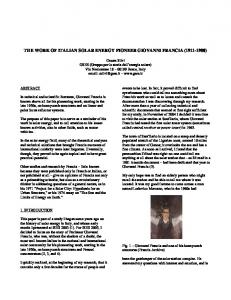
DESIGN RULES FOR AN ANC APPLICATION The first decision in designing an ANC system is deciding whether it is going to use a feedback or feed forward control system. Generally the literature proposes a feed forward control system, if a reference signal can be obtained, as the feed back controller oscillates or is unstable when subjected to higher frequencies [5]. Secondly four physical design parameters have to be considered in a given order to have a useful and working ANC system, namely the control source, error sensor, reference sensor and the control system performance. As stated before, an ANC system generally comprises a reference microphone, an electronic controller, an error microphone and a loudspeaker, which is also called a secondary source to produce the “anti” signal. Therefore the design procedure is as follows [16]: • Determining the control source arrangement, • Determining the error sensor arrangement, • Maximising the quality of the reference signal (in feed forward systems) and • The control system performance, i.e. the performance of the signal processing unit If global sound attenuation is required, then the rule developed by Nelson [12] applies here, that is if there is one noise source and one control source the distance between the two sources must be less than one tenth of the wavelength, λ, of the noise to achieve a noise reduction of 10 dB. Clearly this rule applies more easily at low frequency ranges in respect of placing the two sources close enough to each other. However, if only local control of sound is required, the control source can be located remote from the primary source, where sound attenuation can only be realized around the error microphone, which is restricted to an extent of a tenth of the wavelength of the targeted noise frequency [3]. Again here it is obvious that the zone of quiet around the error microphone will be very small at high frequencies, e.g. a zone of quite of λ/10 = 1.4 cm in diameter at a frequency of 2.5 kHz. The second stage of the design is deciding where the error sensor should be placed. As explained by Hansen et al [7], to have a stable ANC system the gain margin H(ω) must be between 1 and 2, which can achieved according figure 2 and can be expressed as in equation 1. y Error Sensor (xe/ye/ze)
Reference Sensor (xr/yr/zr)
r4 r3 r1 Noise (Primary source) (0e/0e/0e) z
r2 d
Control Source (Secondary source) (xs/ys/zs)
x
Figure 2 – Source and sensor geometry for single channel system [7]
E. Kaymak, M. Atherton, K. Rotter and B. Millar
r3 rr r H (ω ) = 2 3 = 4 r1 r1 r4 r2
(1)
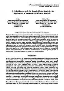
To ensure a gain margin greater than H(ω) > 1 the following relation can be written: r3 r1 (2) > r4 r2 However if the gain margin becomes greater than 2 the system may become unstable and hence the gain margin has to be set to a value between 1 and 2 [7]. The third design factor is the placement and quality of the reference sensor. The distance between the reference sensor and the secondary source must be far enough to ensure causality. Causality is ensured when the time for the acoustic wave travelling from the noise source to the error microphone is longer than the time for the signal picked up by the reference sensor travelling through the reference sensor, the signal processor and the control source [7], i.e. mathematically the following relation must be ensured Ta > Te . Noise
Ta
Err. Mic.
Ref. Mic.
Te
ADC DSP DAC Figure 3 – Causality of an ANC system
Despite this, realizing the causality constraint is easier for periodic noise sources, i.e. for noise generated by rotating parts, because it is largely predictable. And even if causality is not possible the system can still effectively control narrow band or periodic noise [11]. Additionally the electronic delay through the A/D converter, DSP and the D/A converter is lower for higher frequencies and hence an advantage for such applications as it does not contribute to this limitation of ANC as for low frequencies [1].
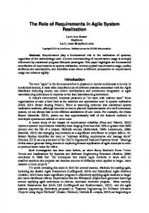
DENTAL DRILL NOISE CHARACTERISTICS Dental drill noise is very uncomfortable for patients [17] and potentially harmful to dental staff [18] and these concerns stimulated this investigation into a possible ANC application. A “headrest system”, where loudspeakers are mounted to the seat around the head of the person, appears to be a possible option for this application. However, further investigations into dental drill noise characteristics revealed that this application exhausts the physical limitations of existing ANC capabilities. The main reason is that the main peaks of dental drill noise occur at higher frequencies than current ANC applications. High speed dental drills, which are used mainly for cutting purposes in a dental surgery, work at a speed of 200000 to 350000 revolutions per minute. Therefore the generated noise peaks begin in a frequency range from 2 - 3 kHz, whereas current ANC applications are below 1 kHz [3]. The exact peak frequency depends on the different drill manufacturers, who use different bearing and design configurations. The noise also has harmonics at higher frequencies, between 5 kHz and 10 kHz but here the frequency of interest is the first peak. Figure 4 shows the power spectral density plot of a high speed dental drill.
Figure 4 – Power Spectral Density of a dental drill
In figure 4 the first peak between 2 and 3 kHz is caused by the handpiece bearings and is therefore a periodic noise. Even during the drilling process the rate of change of the peak frequency is small enough (ca. 200 Hz/sec) that an adaptive control system can follow the peak in real time [8]. As mentioned above this frequency is significantly higher than current ANC can be applied. However, by just filtering this peak the most unpleasant component of the drill noise is removed [8]. Normally, a passive filtering approach could satisfy this problem, but even when this
E. Kaymak, M. Atherton, K. Rotter and B. Millar
is done with conventional noise protection headphones, the patient can still perceive this annoying part of the noise, because it is still large relative to the rest of the sound. The perception of the patient must be considered in this application. Although headphones can reduce the dental drill noise due to the presence of high frequency components, but the reduction is not sufficient and so the patient would still perceive the annoying components of the drill noise. As explained in [17] the most fearful situation during a dental treatment is the drill and everything what is associated to it. Therefore the use of active noise control methods in combination with headphones to optimize the noise reduction is intended. The following section proposes a system which would be suitable for an ANC system for dental drill noise.
PROPOSED ANC SYSTEM FOR DENTAL DRILL NOISE The application of ANC on dental drill noise involves higher frequencies as explained through the paper. Therefore it has to be justified how ANC can be applied to it. Realisation of such a system has to involve some preconditions. The zone of quiet at the targeted frequencies will be small, if it is considered that the drill noise peak occurs in most cases around 2.5 kHz. E.g. theoretically a zone of quiet of 3.44 cm (diameter) for 1 kHz; 2.29 cm for 1.5 kHz, 1.3 cm for 2.5 kHz can be achieved. Therefore for an implementation it is proposed to keep the application area as small as possible. This can be achieved in a headphone. Hence the stability consideration related with the gain margin and described by equation 2 is easy to realise as the quotient of the distance between the noise source and reference sensor over the distance between the reference sensor and control source will be very small, in comparison to the quotient of the distance between noise source and error sensor over the distance between error sensor and control source. The causality constraint can be neglected here as the noise source is periodic and the application targets only the frequency band where the peak occurs, which can be considered as narrow band noise. The reference signal for the signal processor (adaptive algorithm) can be obtained with a microphone. However, there are other ways of obtaining the signal due to the periodic characteristic of the noise. A tachometer can be used to obtain the signal. In addition to it the electric signal for the dental drill driven by an electric motor can be used due to its relation to the rotation speed of the drill. Therefore the high quality of the reference signal will be ensured. With the use of a Texas Instruments TMS320C6713 starter kit it is possible to implement the system very easily. The TI C6713 processor is the digital signal processor with the highest performance on the market at the moment. The implementation is done using Matlab Simulink and its related tools, which eases the whole implementation procedure. It is aimed to implement the system in a headphone to have a controlled small area and to produce the anti noise for the specific narrow band frequency of interest, i.e. ca for 2.5 kHz. It is expected that the produced anti noise cancels the drill noise peak, which will optimize the cancellation through the passive headphone.
CONCLUSIONS It has been shown that current active noise control (ANC) applications and research are focussed on frequencies lower than 1 kHz, due to the physical limitations of the technology. The limitations were listed and it has been shown that fundamental rules govern the application of ANC. However, in the intended drill noise application some of the limitations such as the causality constraint and the application to narrow band noise make it possible thinking about applying ANC in the frequencies of interest. Therefore the narrow band noise peak characteristic of the drill noise was highlighted. Finally a possible implementation of an ANC system was discussed. Further steps for an experimental test rig are planned.
REFERENCES [1] Antila M., “Contemporary electronics solutions for active noise control”, Proceedings of the Active 04, Virginia, USA, (2004). [2] Bullmore A. J., Nelson P. A., Curtis A. R. D., Elliott S. J., “The active minimization of harmonic enclosed sound fields, part II: A computer simulation, Journal of Sound and Vibration”, 117 (1), 15-33, (1987). [3] Elliott S.J., Signal Processing for Active Control, (Academic Press, London, 2001). [4] Elliott S.J., Curtis A. R. D., Bullmore A. J., Nelson P. A., “The active minimization of harmonic enclosed sound fields, part III: Experimental Verification”, Journal of Sound and Vibration, 117 (1), 35-58, (1987). [5] Garcia-Bonito J., Elliott S.J., Boucher C.C., “Generation of zones of quiet using a virtual microphone arrangement”, Journal of Acoustical Society of America, 101, 3498 – 3516, (1997). [6] Hansen C.H., “Current and future industrial applications of active noise control”, Proceedings of the Active 04, Virginia, USA, (2004). [7] Hansen C.H., Snyder S.D., Active Control of Noise and Vibration, (E & FN Spon, London, 1997). [8] Kaymak E, Rotter K R G, Atherton M A, Millar B, “Adaptive Filtering of Dental Noise”, Proceedings of the REM 2005, Annecy, France, (2005). [9] Hansen C.H., Understanding Active Noise Cancellation. (Spon Press, London, 2001). [10] Kuo S.M., Morgan D.M., Active Noise Control systems: algorithms and DSP implementations, (John Wiley & Sons, New York, 1996) [11] Kuo S.M., Morgan D.R., “Active Noise Control: A Tutorial Review”, Proceedings of the IEEE, 87(6), 943 – 973, (1999). [12] Nelson P. A., Curtis A. R. D., Elliott S. J., Bullmore A. J., “The active minimization of harmonic enclosed sound fields, part I: Theory”, Journal of Sound and Vibration, 117 (1), 113 (1987). [13] Olsen H.F., “Electronic Sound Absorber”. Journal of the Acoustical Society of America, 25, 1130-1136 (1953). [14] Pawelczyk M., “Adaptive noise control algorithms for active headrest system”, Control Engineering Practice, 12, 1101 – 1112, (2004).
E. Kaymak, M. Atherton, K. Rotter and B. Millar
[15] Rafaely B., Elliott S.J., Garcia-Bonito J., “Broadband performance of an active headrest”, Journal of the Acoustical Society of America, 106 (2), 787-793, (1999). [16] Snyder S.D., Active Noise Control Primer, (Springer-Verlag, New York, 2000). [17] Stouthard M.E.A., Hoogstraten J., “Ratings of fears associated with twelve dental situations”, Journal of Dental Research, 66 (6), 1175-1178, (1987). [18] Wilson C.E., Vaidyanathan T.K., Cinotti W.R., Cohen S.M., Wang S.J., “Hearingdamage Risk and Communication Interference in Dental Practice”, Journal of Dental Research, 69 (2), 489-493, (1990). [19] Yuan J., “Virtual sensing for broadband noise control in a lightly damped enclosure”, Journal of the Acoustical Society of America, 116 (2), 934-941, (2004).