Journal of Grid Computing 1: 25–39, 2003. © 2003 Kluwer Academic Publishers. Printed in the Netherlands.
25
Mapping Abstract Complex Workflows onto Grid Environments Ewa Deelman1 , James Blythe1 , Yolanda Gil1 , Carl Kesselman1, Gaurang Mehta1 , Karan Vahi1 , Kent Blackburn2 , Albert Lazzarini2 , Adam Arbree3 , Richard Cavanaugh3 and Scott Koranda4 1 Information
Sciences Institute, University of Southern California, Marina Del Rey, CA 90292, USA E-mail:
[email protected] 2 California Institute of Technology, 1200 East California Boulevard, Pasadena, CA 91125, USA 3 Department of Physics, University of Florida, Gainesville, FL 32611-8440, USA 4 Department of Physics, University of Wisconsin, Milwaukee 1900, East Kenwood Blvd, Milwaukee, WI 53211, USA
Key words: complex applications, planning, reliability, workflow management
Abstract In this paper we address the problem of automatically generating job workflows for the Grid. These workflows describe the execution of a complex application built from individual application components. In our work we have developed two workflow generators: the first (the Concrete Workflow Generator CWG) maps an abstract workflow defined in terms of application-level components to the set of available Grid resources. The second generator (Abstract and Concrete Workflow Generator, ACWG) takes a wider perspective and not only performs the abstract to concrete mapping but also enables the construction of the abstract workflow based on the available components. This system operates in the application domain and chooses application components based on the application metadata attributes. We describe our current ACWG based on AI planning technologies and outline how these technologies can play a crucial role in developing complex application workflows in Grid environments. Although our work is preliminary, CWG has already been used to map high energy physics applications onto the Grid. In one particular experiment, a set of production runs lasted 7 days and resulted in the generation of 167,500 events by 678 jobs. Additionally, ACWG was used to map gravitational physics workflows, with hundreds of nodes onto the available resources, resulting in 975 tasks, 1365 data transfers and 975 output files produced.
1. Introduction Grid computing [20, 21] promises users the ability to harness the power of large numbers of heterogeneous, distributed resources: computing resources, data storage systems, instruments etc. These resources are distributed in the wide area and belong to testbeds in the US, Europe, Asia and Australia. The vision is to enable users and applications to seamlessly access these resources to solve complex large-scale problems. Scientific communities ranging from highenergy physics [30], gravitational-wave physics [16], geophysics [41], astronomy [4], to bioinformatics [36] are embracing Grid computing to manage and process large data sets, execute scientific simulations and share
both data and computing resources. Scientific, data intensive applications, such as those outlined above are no longer being developed as monolithic codes. Instead, standalone application components are combined to process the data in various ways. The applications can now be viewed as complex workflows, which consist of various transformations performed on the data. For example, in astronomy, workflows with thousands of tasks need to be executed during the identification of galaxy clusters within the Sloan Digital Sky Survey [4]. Because of the large amounts of computation and data involved, these workflows require the power of the Grid to execute efficiently. The NSF-funded Grid Physics Network (GriPhyN) [30] project aims to provide users a seam-
26 less access to data, whether it is computed or whether it exists only in the form of an application-level description. This class of data is referred to as Virtual Data. In GriPhyN, a user should be able to request data by simply submitting an application-specific description of the desired data product. The Grid infrastructure should then be able to generate a workflow by selecting appropriate application components, assigning the required computing resources and overseeing the successful execution. This mapping should be optimized based on criteria such as performance, reliability, resource usage etc. Up to now much of the focus of Grid computing has been on developing middleware, which provides basic functionality such as the ability to query for information about the resources and the ability to schedule jobs onto the resources. With few exceptions, such as the European Data Grid Resource Broker [27] described in Section 6, little work has been done in the area of automating job execution. Users still need to discover resources manually and schedule the jobs directly onto the Grid, essentially composing detailed workflow descriptions by hand. This leaves users struggling with the complexity of the Grid and weighing which resources to use, where to run the computations, where to access the data etc. The goal of our work is to automate this workflow generation process as much as possible. We introduce the notion of abstract workflows that specify application components and input data, and concrete workflows that include references to actual executables and data files as well as specific resources. The applicability of various techniques that can be used to perform the workflow generation can vary depending on the application’s characteristics and complexity. For simple workflows, such as the current Compact Muon Solenoid (CMS) [47] workflow, the Concrete Workflow Generator (CWG) described below is sufficient. CWG takes an abstract workflow and makes simple mappings based on data location and resource availability to generate a feasible concrete workflow. CWG also optimizes the concrete workflow based on the availability of intermediate data products. For other more complex application workflows, such as those needed by the Laser Gravitational Wave Observatory (LIGO) [1, 5], more sophisticated mappings need to be employed. We believe that as the complexity of the problem space grows and the sophistication of the desired optimizations increases, we can greatly benefit from the use of Artificial Intelligence (AI) based planning techniques to search for solutions. An additional benefit of AI-based techniques
is their ability to abstract the problem to the level of the application. This allows us to map directly from the individual application components to the concrete workflow. To underline the importance of developing automatic workflow mapping systems, we show that providing even simple feasible mappings can make an impact in the application domain. Specifically, we demonstrate the use of CWG to a problem presented to the Grid by the CMS experiment. This effort is building and experimenting with the Grid in advance of collecting the data from the particle colliders. In particular CMS is using the Grid to prepare for the CMS detector which is due to begin collecting data at the European Center for Nuclear Research (CERN) in 2007. At that time large amounts of data will be collected and will need to be analyzed in real time. CMS is currently running Grid enabled simulations in which physics events are generated and their appearance in the CMS detector is simulated. These simulations are geared towards verifying the detector design and the design of the grid-enabled real-time event processing algorithms, which will analyze the data coming from the CMS detector. We also show the usefulness of applying AI-based techniques to generating LIGO workflows based on the metadata description of the LIGO pulsar search, an analysis frequently performed by the scientists. LIGO is a distributed network of four-km-scale interferometers occupying two sites in the U.S. The construction project was funded by NSF and jointly built by Caltech and MIT. The observatory’s mission is to detect and measure gravitational waves predicted by general relativity, Einstein’s theory of gravity, in which gravity is described as due to the curvature of the fabric of spacetime and space. LIGO has started collecting scientific data in 2002 and plans to have several long-duration runs in the coming years. The remainder of this paper is organized as follows. Section 2 states the problem from the point of view of the application. Section 3 describes the Concrete Workflow Generator that produces a feasible concrete workflow through simple mapping techniques. Section 4 describes an alternative and more powerful approach that exploits AI-based planning techniques. Section 5 describes the experiences with using our system within the context of CMS and LIGO. Finally Sections 6 and 7 describe the related work, provide conclusions, and elaborate on the challenges and opportunities ahead.
27 2. Problem Description Scientists often seek specific data products, which can be obtained by configuring available application components and executing them on the Grid. As an example, suppose that the user’s goal is to obtain a frequency spectrum of a signal S from instrument Y and time frame X, placing the results in location L. In addition, the user would like the results of any intermediate filtering steps performed to be available in location I, perhaps to check the filter results for unusual phenomena or perhaps to extract some salient features to the metadata of the final results. The process of mapping this type of user request into jobs to be executed in a Grid environment can be decomposed into two steps, as shown in Figure 1. 1. Generating an abstract workflow: Selecting and configuring application components to form an abstract workflow. The application components are selected by looking at the specification of their capabilities and checking if they can generate the desired data products. They are configured by assigning input files that exist or that can be gener-
ated by other application components. The abstract workflow specifies the order in which the components must be executed. More specifically, the following steps need to be performed: a. Find which application components generate the desired data products, in our example a frequency spectrum of the desired characteristics. Let one such component be Cn . Find which inputs that component takes, check if any inputs are available and if so let the corresponding files be I1 . . . Ij . If any input is required in formats that are not already available then find application components that can produce that input, let one such component be Cn−1 . This process is iterated until the desired result can be generated from a composition of available components that can operate over available input data, namely C1 . . . Cn and I1 . . . Im respectively. b. Formulate the workflow which specifies the order of execution of the components C1 . . . Cn . This is what we call an abstract workflow. Please note that at this level the components and files are referred to by their logical names which
Figure 1. The process of developing data intensive applications for Grid environments.
28 uniquely identify the component in terms of their functionality and the data files in terms of their content, but a single logical name can correspond to many actual executables and physical data files in different locations. 2. Generating concrete workflow: Selecting specific resources, files, and additional jobs required to form a concrete workflow that can be executed in the grid environment. Each component in the abstract workflow is turned into an executable job by specifying the locations of the physical files of the component and data as well as the resources assigned to it in the execution environment. Additional jobs may be included in the concrete workflow. For example, jobs that transfer files to the appropriate locations where resources are available to execute the application components. More specifically, the following steps need to be performed: a. Find the physical locations (i.e., physical files) of each component C1 . . . Cn : C1 -pf . . . Cn -pf. b. Check the computational requirements of C1 -pf . . . Cn -pf and specify locations L1 . . . Ln to execute them according to the required and available resources. c. Determine the physical locations of the input data files I1 -pf . . . Im -pf, select locations that seem more appropriate given L1 . . . Ln . d. Augment the workflow description to include jobs K1 . . . Km+n to move component and input data files (C1 -pf . . . Cn -pf and I1 -pf . . . Im -pf) to the appropriate target locations L1 . . . Ln . Although Grid middleware allows for discovery of the available resources and of the locations of the replicated data, users are currently responsible for carrying out all of these steps manually. There are several important factors that make automating this process not only desirable but necessary: • Usability: Users are required to have extensive knowledge of the Grid computing environment and its middleware functions. For example, the user needs to understand how to query an information service such as the Monitoring and Discovery Service (MDS) [14], to find the available and appropriate computational resources for the computational requirements of a component (step 2b). The user also needs to query the Replica Location Service (RLS) [13] to find the physical locations of the data (step 2c). • Complexity: In addition to requiring scientists to become Grid-enabled users, the process may be
complex and time consuming. Notice that in each step, the user makes choices when alternative application components, files, or locations are available. The user may reach a dead end where no solution can be found, which would require backtracking to undo some previous choice. Many different interdependencies may occur among components, and as a result it may even be hard to determine which choice to change and what would be a better option that leads to a feasible solution. • Solution cost: Lower cost solutions are highly desirable in light of the high cost of some of the computations and the user’s limitations in terms of resource access. Because finding any feasible solution is already time consuming, users are unlikely to explore alternative workflows that may reduce execution cost. • Global cost: Because many users are competing for resources, minimizing cost within a community or a virtual organization (VO) [21] is desirable. This requires reasoning about individual user’s choices in light of other user’s choices, such as possible common jobs that could be included across user’s workflows and executed only once. While addressing the first three points would enable wider accessibility of the Grid to users, the last point of handling global cost simply cannot be handled by individual users and will likely need to be addressed at the architecture level. In addition, there are many policies that limit user’s access to resources, and that needs to be taken into account in order to accommodate as many users as possible while they are contending for limited resources. An additional issue is the reliability of execution. In today’s Grid framework, when the execution of a job fails the recovery consists of resubmitting that job for execution on the same resources. (In Figure 1 this is shown as the “retry”.) However, it is also desirable to be able to choose a different set of resources when tasks fail. This process needs to be performed at the abstract workflow level. Currently, there is no mechanism for opportunistically redoing the remaining tasks in the workflow to adapt to the dynamic situation of the environment. Moreover, if any job fails repeatedly it would be desirable for the system to assign an alternative component to achieve the same overall user goals. This would need to be performed at the application level, where there is an understanding of how different application components relate to each other. In Table 1 we describe three different levels of abstraction that a user can use to specify a workflow. At
29 Table 1. Levels of abstraction used to describe workflows. Concrete workflow domain
Abstract workflow domain
Application domain
Specification
Gridftp host1://home/filea host2://home/file1 /usr/local/bin/fft–i /home/file1
FFT filea
Frequency spectrum of a signal S from instrument Y and time frame X
Specification detail
Resource level physical files executables
Logical file names, logical component names
Application-specific metadata
the lowest level (concrete workflow) the user needs to specify explicit data movements and the exact executables and resources to be used. At the abstract workflow level the user needs only specify the workflow using logical files and logical component names. Finally at the top level, the application level, the user needs to specify only the metadata describing the desired data products. In Section 3 we describe the implementation of a Concrete Workflow Generator (CWG). CWG performs the mapping from an abstract workflow to a concrete workflow. The system automatically locates physical locations for both components and data, finds appropriate resources to execute the components and generates an executable workflow of jobs that can be submitted to the Grid. Although this implementation isolates the user from many details about the Grid infrastructure, it still requires the user to spell out all the components and input files required. In addition, whenever several alternatives are possible (e.g., alternative physical files, alternative resources) it makes a random choice, so the final result is a feasible solution and not necessarily a low-cost one. In Section 4, we describe the implementation of an Abstract & Concrete Workflow Generator (ACWG) which only requires from users an abstract description of the desired data products in terms of applicationspecific metadata. The approach we used was to exploit Artificial Intelligence planning techniques that explore the solution space with search algorithms guided with informed heuristics.
3. Concrete Workflow Generator Before we discuss the Concrete Workflow Generator (CWG), we briefly describe the Grid environment where the jobs are being executed. In the Grid [21],
resources, computational, data, instruments are distributed in the wide area. To manage the information and interactions with these resources, the Globus toolkit [29] is deployed on the resources. Globus consists of services, which allow for the discovery of the resources and their characteristics (via MDS [14]). It also allows for scheduling of jobs onto the resources (via GRAM [15]). In terms of data management, Globus provides information about locating replicas of files (via RLS [13]) and the means of highperformance data transfer (via GridFTP [2]). As part of the GriPhyN project [30] we are also developing a Transformation Catalog [18] which provides a mapping between the application components and their physical location. Another component developed as part of GriPhyN is the Virtual Data Catalog [19, 22] which can keep track of which components were used to generate data products. CWG performs a mapping from an abstract workflow to a concrete workflow (both represented as Directed Acyclic Graphs (DAGs)), taking into account the previous calculation of intermediate data products, and inserting data movement and data publishing operations, where appropriate. The CWG could be termed an “algorithmic mapper” in that it encodes a specific mapping procedure. We contrast this approach with AI based planners which provide a generalized control structure which manipulates domain specific rules. The following is a simple example to illustrate the capabilities of CWG. Figure 2 shows a simple abstract workflow in which the logical component Extract is applied to an input file with a logical filename F.a. The resulting files, with logical filenames F.b1 and F.b2, are used as inputs to the components identified by a logical filename Resample and Decimate respectively. Finally, the results are Concatenated. Let’s assume that F.c2 is already available on some storage system (as indicated by the RLS). CWG reduces the workflow to three components, namely Extract, Resample and Concat. It then adds the transfer
30
Figure 2. Abstract workflow.
Figure 3. Reduced, concrete workflow.
files for transferring F.c2 and F.a from their current locations. It also adds transfer nodes between jobs which will run on different locations, for example, if Resample and Concat are available on two different locations, F.c1 will have to be transferred. Finally CWG adds output transfer nodes to stage data out and registration nodes if the user requested that the resulting data was published and made available at a particular location. The concrete workflow for this scenario is shown in Figure 3. Once the workflow is instantiated in the form of a DAG, software such as DAGMan (Directed Acyclic Graph Manager) and Condor-G [26] are used to schedule the jobs described in the nodes of the DAG onto the specified resources in their specified order. More generally, CWG can be described as follows. The abstract workflow has information about all the jobs needed to be done to materialize the required data. In order to map from the abstract to the concrete workflow, CWG first reduces the abstract workflow. CWG assumes that it is more costly to execute a component (a job) than to access the results of the component if
that data is available. For example, some other user in the VO may have already materialized part or the entire required data set. If this information is published into a replication service then CWG can utilize this knowledge and obtain the data thus avoiding possibly costly computation. As a result, some components that appear in the abstract workflow do not appear in the concrete workflow. During this optimization, the RLS is queried and based on the availability of the output files the jobs which do not need to be executed are identified. Any antecedents of the redundant jobs which do not have any unmaterialized descendents are removed. The reduction algorithm is performed until no further nodes can be reduced. Next, CWG maps the remaining abstract workflow onto the available resources. Currently the information about the available resources is statically configured. In the near future, we plan to include dynamic information provided by MDS. 1. CWG also checks for the feasibility of the abstract workflow. It determines the root nodes for the abstract workflow and queries the RLS for the existence of the input files for these components. The workflow can only be executed if the input files for these components can be found to exist somewhere in the Grid and are accessible via a data transport protocol. The Transformation Catalog is queried to determine if the components are available in the execution environment and to identify their locations. Currently CWG picks a random location to execute from among the returned locations. 2. Transfer nodes are added for any of these files that need to be staged in, so that each component and its input files are at the same physical location. If the input files are replicated at several locations, CWG currently picks the source location at random. 3. Finally transfer nodes and registration nodes, which publish the resulting data products in the Replica Location Service are added if the user requested that all the data be published and sent to a particular storage location. In order to be able to execute the workflow, CWG generates submit files which are given to Condor-G and the associated DAGMan for execution. CWG has been successfully used in mapping and executing CMS workflows as shown in Section 5. Although finding a feasible mapping from the abstract to the concrete workflows is a manageable task, the issue becomes more complicated as the application’s complexity increases and the size of the Grid
31 grows and as one considers optimizations of the concrete workflow. The CMS workflow, for example, consisted of only 5 stages, with each stage composed of only one job. The complexity for CMS comes from the execution of multiple (in the thousands) of workflows to perform adequate analysis. Other applications, such as LIGO, have a similar number of stages, but some of the stages are composed of hundreds of jobs. The complexity of the mapping is also magnified if we consider more sophisticated optimizations. For example, we can take into account information such as network bandwidth, scheduler queue size, reliability of the resource, processing speed storage capacity and others. Based on this system information, one can perform optimizations such as minimizing the total runtime of the workflow, maximizing the probability that the execution will be successful, minimizing the use of “expensive” resources etc. Constraints on the execution of the workflow can be also imposed based on the user’s and the VO’s access privileges to the resources. In the general case, users should also be able to decide which optimization criteria are important to them. In order to be able to support such complexity, the workflow generation system needs to be able to efficiently search this large problem space and apply both local and global optimizations. It also needs to compose the various optimization strategies based on the user and resource requirements. In order to minimize development cost, it also needs to be able to reuse the resource and component models. Although, we could continue incorporating support for these optimizations and local and global search heuristics into CWG, it is far more efficient to use existing technologies, such as AI planners as the platform for the mapping system. AI planning research already has a broad-base, generic implementation foundation which can do efficient searches in large problem spaces. It uses techniques, such as backtracking, and domain-specific and domainindependent control rules to focus the search. It can take into account the interdependencies across choice points during the search, incorporate optimality and policy into the search for solutions, interleave resource assignment with scheduling concerns that take into account job duration. It can also integrate the generation of workflows across users and policies within VOs. AI planners are flexible and allow the easy addition of new system constraints and rules. In the following section, we examine the features of AI planning solutions and apply them to workflow mapping problem.
4. Abstract and Concrete Workflow Generator Planning, as a subfield of artificial intelligence, is concerned with finding a sequence of actions (a plan) that can be used to achieve desired goals [48]. AI planning has been successfully used for challenging practical applications including space mission planning, manufacturing, military logistics and robotics. A typical planning system takes three pieces of input: • A description of the current state of the world in some formal language, called the initial state, • A description of the agent’s goals, usually as a partial description of a world state, and • A library of operators, representing actions that the agent can perform to change the state. Each operator is usually described by a set of preconditions that must hold in any world state in which the action is applied and a set of effects, or changes to the state that will take place when the action is applied. In some planners, called task-decomposition planners, the description also includes a partially ordered set of lower-level operators that must be accomplished in order to achieve the operator at hand. Planning systems can be cast as a search algorithm to find a plan to achieve the goals from the initial state. Many different search strategies are used: some planners search the state space forwards from the initial state or backwards from the goal specification, some search top-down with abstract operators and some search the plan space rather than the state space. In this section we describe how we have framed the ACWG as a planning problem, and mention some planning approaches that seem best suited. In Section 5 we show the results of applying the techniques to the LIGO pulsar search. In Section 7 we describe further work that is needed in planning to better handle the problem. 4.1. Stating the Problem in Planning Terms ACWG models the application components along with data transfer and data registration as operators. Each operator’s parameters include the location where the component can be run. An output plan corresponds to a concrete workflow. In addition, some of the effects and preconditions of the operators can capture the data produced by components and their input data dependencies. As a result the planner can also create an abstract workflow. State information used by the planner includes a description of the available resources
32 and the files already registered in the Replica Location Service. The input goal description can include (1) a metadata specification of the information the user requires and the desired location for the output file, (2) specific components to be run or (3) intermediate data products. Several issues make this application domain challenging, we touch upon them as we describe the domain model in more detail. In our initial work, we are using the Prodigy planner [44]. It provides an expressive language which can be used to define search heuristics important in ACWG. 4.1.1. State Information The planner’s world state includes information about resources. Some of this information changes slowly if at all, such as the operating system or total disk space available on a resource, and some of the information can change in seconds or minutes, such as the available memory or queue length. In the long run the planner may need to reason about how the information can change over time, but in our initial implementation this information is simply captured once at the planner’s startup. The previously created files are also currently modeled in the initial state, but care needs to be taken because thousands or millions of files may be available, while only a relatively small number are relevant to the current plan. The planner can handle this by requesting the relevant information while planning, but currently we filter the set of files before planning begins. It is useful for the planning state to include metadata about the files to enable the planner to create both the abstract and concrete workflows. It is also more appropriate to reason at the level of the metadata rather than at the level of the files that represent that data content. Rather than search for a file with appropriate characteristics, the component descriptions reference the characteristics themselves. This also avoids quantifying over the set of existing files, which may change during planning as objects are created and destroyed. 4.1.2. Goal Statements In most planning applications, goals refer to properties that should be true after the plan has been executed. For ACWG, such goals include having a file described by the desired metadata information on some host. However, it is also sometimes useful to specify goals that refer to intermediate components or data products, or for registering certain files. Thus the goal statement can specify a partial plan. The goals given to the planning system may be those of a single user or the aggregated goals of a
group of users. In the latter case, the planner may be able to create a more efficient plan for the overall computations required by exploiting any synergy in the users’ goals although we currently do not include this capability. This is an example of the interplay between the planning algorithm and any policy settings, briefly discussed below. 4.1.3. Operator Descriptions The operators represent the concrete application of a component at a particular location to generate a particular file or a file movement across the network. Their preconditions represent the data dependencies of the component, in terms of the input information required. These operators capture information similar to that represented in Chimera’s Virtual Data Language [22], such as the name of the component and its parameters. However, the operators also contain the additional information such as the feasible resources for running the component, including the type of resource, minimal physical memory or hard disk space and software configuration. Operators can also define the preconditions necessary for the use of the component, and provide the effect of the application of the component on the state of the system, such as the consumption of the resources. Plans generated in response to user requests may often involve hundreds or thousands of files and it is important to manage the process of searching for plans efficiently. If a component needs to be run many times on different input files, it is not useful for the planner to explicitly consider different orderings of those files. Instead the planner reasons about groups of files that will be treated identically. Auxiliary routines allocate the files to different groups, looking for a locally optimal allocations. Since the number of input files or groups may vary by component and even by invocation, the preconditions are modeled using quantification over possible files. We note that this type of abstraction is hard to achieve in non-metadata-based systems such as Chimera and CWG. Below is an example of an operator representing an FFT component used in the LIGO pulsar search (described in Section 5). The operator is defined for a set of input files and describes these files as well as the resulting file in terms of metadata, such as lowtime and hightime, which define the interval of time of the signal over which the FFT is taken. The operator also captures the notion of the availability of the FFT on a resource (host). The effects show the creation of the FFT on the chosen host.
33 (operator fft (params ) (preconds (( File); really a block of files in the current model ( ComputeHost) ( Number) ( Number)) (available fft )) (effects ()
(control-rule select-binding-nearby-mpi-for-pulsar-search (if (and (current-operator pulsar-search) (true-in-state (available fft )) (true-in-state (physically-at )) (true-in-state (physically-at )) (type-of-object Mpi))) (then select bindings ((. )))); is a parameter of the pulsar-search operator
((add (created-fft-on-host )) (add (created )) (add (at )) )))
4.1.4. Solution Space and Plan Generation Strategy In our initial approach, we seek high-quality plans with a combination of local search heuristics, aimed at preferring good choices for individual component assignments, and an exhaustive search for a plan that minimizes the global estimated run-time. Both aspects are necessary: without the global measure, several locally optimal choices can combine to make a poor overall plan because of conflicts between them. Without the local heuristics, the planner may have to generate many alternatives before finding a high quality plan. These local heuristics are represented explicitly in the planner using search control rules [44]. As the planner searches for a solution, it repeatedly chooses a goal to address, an operator to achieve the goal and parameter assignments for the operator. For each choice, the planner may need to backtrack and examine several alternatives in order to find a feasible plan, and search further to find the best plan. Search control rules can specify options that should be exclusively considered at any choice point in the search algorithm. They can also change the order in which options are considered. The rules can refer to information about the current state when the choice is made, or to other goals in the planner. For example, a rule can be used to prefer to allocate a component to a location with a higher-bandwidth connection to the location at which the component’s output is needed. This rule is applicable in almost any ACWG problem. Application-specific rules can also be defined. For example, the following control rule would force the planner to choose a host to perform the LIGO pulsar search that is in the same location as a host that can perform the FFT, if possible.
The AI planner is able to produce results similar to CWG in several test scenarios using 3 operators and 2 control rules, although it currently supports a broader range of problems using 9 operators and 17 control rules. It takes less than half a second to find its first solution in a LIGO pulsar search problem with around 400 files and 10 locations, requiring 800 separate components, and around 30 seconds to exhaustively search the solutions for this problem. In the worst case it scales exponentially with the number of resources and the depth of the plan, however in this domain the time to find the first plan will scale linearly in the number of files and resources. A more detailed planner description can be found in [8]. 5. Application Experiences As part of this work we have developed a configurable system, Pegasus (Planning for execution in Grids) [17] and integrated it into Chimera [23]. In Chimera the user specifies the abstract descriptions of a component (the arguments it takes etc, the number of input and output files), which is defined using the Chimera Virtual Data Language (VDL). The language also defines derivations which are invocations of a particular component and contain logical file names (lfn) and parameters used to run that component. The derivations are used to construct abstract workflows. In the Chimera-driven configuration Pegasus receives an abstract workflow description from Chimera and uses CWG to produce a concrete workflow. Pegasus then submits the concrete workflow to DAGMan for execution and monitors the jobs described in the concrete workflow. We have used this configuration to map CMS workflows onto the Grid. 5.1. Applying CWG to CMS The Compact Muon Solenoid (CMS) is a multipurpose particle physics detector currently being constructed at the European Center for Nuclear Research
34
Figure 4. The abstract workflow for a CMS n-tuple-only production is a linear five-stage pipeline.
(CERN) in Geneva, Switzerland [47]. When it begins operation in 2007, the CMS detector is expected to record data, produced by high-energy proton-proton collisions occurring within CERN’s Large Hadron Collider (LHC), at a rate of 100 MB/s [32]. After the data is recorded, it will be passed through various filter stages which transform and reduce the data into formats which are more easily analyzed by physicists. In order to better understand the response of the detector to different input signals, large scale, Monte Carlo simulations are performed which typically involve several different computational stages. These simulations are long-running, parallel, multi-stage processes that are ideally suited for Grid computation [33]. Typically, a single workflow creates approximately 1 GB of data and requires 10 to 20 CPU/hours depending on the type of simulation. A typical production run may include thousands of workflows. A variety of different use-cases exist for simulated CMS data production. One of the simpler use-cases is known as an n-tuple-only production which consists of a five stage computational pipeline shown in Figure 4. The first is a generation stage that simulates the underlying physics of each event. The second stage is a simulation stage that models the CMS detector’s response to the events created in the generation stage. The third stage, or formatting stage, copies the simulated detector data into an object-oriented database (OODB). The next stage, or reconstruction stage, transforms the data in the database, producing a “picture” of what a physicist would “see” as if the simulated data were actual data recorded by the experimental apparatus. The final stage, an analysis stage, selects user-specific information from the database and creates a convenient, easy to use file that can be analyzed by a researching physicist. In an n-tuple-only production, the last file, an ntuple, is the only important piece of data and the intermediate data may be discarded. However, the log files for the intermediate data products are needed
for quality assurance validation. Several small scale tests of CMS n-tuple-only production pipelines have been successfully performed using CWG. CWG was also used for a large scale test which involved twostage pipelines (generation and simulation). CWG scheduled this work to be performed at a University of Florida computing cluster consisting of 25 dualprocessor Pentium (1 GHz) machines. Over the course of 7 days, 678 jobs of 250 events each were submitted using CWG. From these jobs, 167,500 events were successfully produced using approximately 350 CPU/days of computing power and producing approximately 200 GB of simulated data. 5.2. Applying ACWG to the LIGO Pulsar Search LIGO (Laser Interferometer Gravitational-Wave Observatory, www.ligo.caltech.edu) [1, 5] is a distributed network of interferometers whose mission is to detect and measure gravitational waves predicted by general relativity, Einstein’s theory of gravity. One well-studied source of gravitational waves is the motion of dense, massive astrophysical objects such as neutron stars or black holes. Other signals may come from supernova explosions, quakes in neutron stars, and pulsars. Gravitational waves interact extremely weakly with matter, and the measurable effects produced in terrestrial instruments by their passage is expected to be miniscule. In order to establish a confident detection or measurement, a large amount of auxiliary data will be acquired (including data from seismometers, microphones, etc.) and analyzed (for example, to eliminate noise) along with the strain signal that measures the passage of gravitational waves. The raw data collected during experiments is a collection of continuous time series at various sample rates. The amount of data that will be acquired and cataloged each year is on the order of tens to hundreds of terabytes. The gravitational wave strain channel is less than 1% of all data collected. Analysis on
35
Figure 5. The LIGO pulsar search.
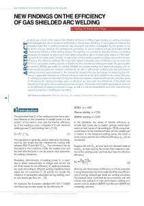
the data is performed in both time and frequency domains. Requirements are to be able to perform single channel analysis over a long period of time as well as multi-channel analysis over a short time period. To investigate the capability of ACWG to generate complex, metadata driven workflows, we integrated ACWG into Pegasus and applied it to a specific LIGO analysis, the pulsar search. In the ACWG-driven configuration, Pegasus is driven by the metadata of the search, which can be implemented as a pipeline depicted in Figure 5. The first element in Figure 5 is data archiving as instrumental data is stored into an archive. Next, since, the raw data comes from the instrument as short (16 second duration) Frames (a data structure used in the gravitational wave community) with all the channels, some processing geared towards the removal (cleaning) of certain instrumental signatures needs to be done. For example, naturally occurring seismic vibration can be subtracted from the data using the channels from the sensitive seismometer that is part of the LIGO data stream. For the pulsar search, the gravitational wave strain channel is extracted. The pulsar search is conducted in the frequency domain; thus Fourier Transforms are performed on the long duration time frames to produce datasets known as Short Fourier Transforms (SFTs). Since the pulsars are expected to be found in a small frequency range, the frequency interval of interest is extracted from the STFs. The resulting power spectra are used to build the time-frequency image, which is analyzed for the presence of pulsar signatures. If a candidate signal with a good signal to noise ratio is found, it is placed in LIGO’s event database.
The LIGO pulsar search is performed using the Pegasus system, in the configuration which included ACWG. The compute and storage resources were at Caltech, University of Southern California and University of Wisconsin Milwaukee. In a run conducted at SC 2002, over 58 pulsar searches were performed resulting in a total of 330 tasks, 469 data transfers executed and 330 output files. The total runtime was 11:24:35. 6. Related Work While AI planning techniques focus on choosing a set of actions to perform to achieve given goals, scheduling techniques focus on assigning resources for an already chosen set of actions. Some recent approaches in scheduling have had success using iterative refinement techniques [43] in which a feasible assignment is gradually improved through successive modifications. The same approach has been applied in planning and is well suited to ACWG, where plan quality is important [3]. Some work has been done on integrating planning and scheduling techniques to solve the joint task [35]. Central to scheduling large complex workflows is the issue of data placement, especially when the data sets involved are very large. In CWG we give preference to the resources where the input data set is already present. Others [37, 38] look at the data in the Grid as a tiered system and use dynamic replication strategies to improve data access. In [39] significant performance improvement is achieved when scheduling is performed according to data availability while also using a dynamic replication strategy.
36 While running a workflow on the Grid makes it possible to perform large computations that would not be possible on a single system, it leads to a certain loss of control over the execution of the jobs as they might be executed in different administrative domains. To counter this, there are other systems ([10, 11]; Abramson, R. Buyya et al., to appear; P. Keyani, N. Sample et al., Stanford Database Group), which try to provide Quality of Service guarantees required by the user while submitting the workflow to the Grid. NimrodG uses the information from the MDS to determine the resource which meets the budget constraints specified by the user, while (P. Keyani, N. Sample et al., Stanford Database Group) monitors a job progress over time to ensure that guarantees are being met. If a guarantee is not being met schedules are recalculated. Other work has focused on developing application specific schedulers, which maximize the performance of the individual application. In AppLeS [6], scheduling is done on the basis of a performance metric which varies from application to application. To schedule the jobs on the Grid, knowledge is required about resource usage. This leads to a customized scheduler for each application and not a general solution. Some schedulers have focused on parameter sweep applications, where a single application is run multiple times with different parameters [12]. Since there are no interdependencies between jobs, the scheduling process is far simpler from the one addressed here. The European Data Grid (EDG) also has considered the automatic scheduling of jobs on the Grid which resulted in the development of their Workload Management Package [27]. The EDG Resource Broker [40] maps individual jobs based on information provided by various Grid Services such as MDS, Network Weather Service [46] and the Replica Location Services. Each of the systems mentioned above are rigid because they use a fix set of optimization criteria. In this work we are developing a framework for a flexible system that can map from the abstract workflow description to its concrete form and can dynamically change the optimization criteria.
near future we plan to evaluate approaches such as plan reuse and planning under uncertainty to increase the level of ACWG’s performance and sophistication. We also plan to investigate the applicability of our approach to service-level composition. In this section we describe some of our ideas. 7.1. Solution Reuse One important research area that is likely to be effective for this problem is the reuse of solutions that were previously computed. Case-based planning is a powerful technique to retrieve and modify existing plans that need slight changes to be adapted to the current situation [45, 31]. These approaches have potential for ACWG because the network topology and resource characteristics are likely to be fairly stable and therefore high-quality solutions, which may take time to generate from first principles, will be good starting points for similar problems in the future. 7.2. Fault Avoidance In the simple case, the planner creates a plan that is subsequently executed without a hitch. Often, however, runtime failures may result in the need to repair the plan during its execution. Planning systems can also design plans that either reduce the risk of execution failure or are more likely to be salvageable when failures take place. They can explicitly reason about the risks during planning and searching for reliable plans, possibly including conditional branches in their execution ([7, 9]). Some planners delay building parts of the plan until execution, in order to maintain a lower commitment to certain actions until key information becomes available. These approaches are likely to have high impact in the Grid computing domain, since its decentralized nature means many factors are beyond the control of the planning agent. However current techniques for handling uncertainty have high complexity, and are not useable when more than a few potential failure points need to be considered.
7. Future Directions and Conclusions
7.3. Relevance to Open Grid Services Architecture and Use of Ontologies
Finding good abstract and concrete workflows involves a wide range of issues that have been investigated in Artificial Intelligence planning, including hierarchical planning, temporal reasoning and scheduling, reasoning about resources, planning under uncertainty and interleaving planning and execution. In the
Although much work needs to be done in the area of workflow generation, we believe that the framework we designed is a good foundation for developing ever more sophisticated techniques, which will take into account an ever greater amount of information about the applications and the execution environment.
37
Figure 6. A general view of the mapping system and the information and necessary models.
Figure 6 illustrates additional sources of information that we would like to integrate in the future within the workflow generation process. At the application level, we can describe the application components as services, which would facilitate the integration of our work with the new Open Grid Services Architecture (OGSA) [24, 25]. These services can be composed into new more sophisticated services. Although OGSA provides a syntactic description of the services (via WSDL) it does not assign any semantic meaning to them. We propose to augment service-based component descriptions by developing ontologies of application components and data, which will describe the service behavior and add semantic meaning to the service interactions. Ontologies will allow us to generate abstract workflows more flexibly from user requirements that may be partially complete or specified at higher levels of abstraction than the current service descriptions. Additional information provided by performance models of the services can guide the initial composition. We also see ontologies playing a very important role in generating concrete workflows. Ontologies of Grid resources would allow the system to evaluate the suitability of given resources to provide a particular application service instance. The resources that are to be allocated to various tasks can often be characterized in a domain-independent way by how they are used. For example, a computer system becomes available again once a task has been completed but a user’s allocation of time on a particular machine is permanently depleted. Ontologies of resources capture these qualities (e.g., [42, 28]). Such ontologies, along with others which can capture computer system capabilities and job requirements, are key in building planning domains for ACWG quickly and reliably from generic components. However, there has been little work in this area of engineering planning domains, although an example is [34].
7.4. Incorporating Policy Descriptions In addition, in order to generate a feasible workflow, information such as policies governing the members of a Virtual Organization must be provided. For example, given an allotment of resources, the VO might decide to grant more resources to particular individuals. At the same time resources themselves need to provide information about the policies that they enforce both at the VO and user levels. The resources also have to provide information about their current state. Given a feasible solution, CWG also needs to provide an optimal solution, considering policies in part but also the overall behavior of the application. 7.5. Conclusions In this paper we addressed the issue of composing complex applications and mapping them on the Grid resources. We have identified two important steps that need to take place. The first step is to map application requirements in terms of desired data products to an abstract workflow that specifies what application components can generate the data. The second step maps the workflow onto Grid resources. We described two mappings: CWG, which takes an abstract workflow, generates a random feasible solution and performs modest optimizations, and ACWG which can perform both steps. We have exploited and adapted AI planning techniques in ACWG to express the mapping problem using application-specific metadata. ACWG makes use of operator-based plan generation and combines local heuristics and a global measure to look for high-quality plans. We applied CWG to an important application domain – the high energy physics experiment CMS. CWG was used by the CMS physicists to conduct production-quality simulations on their Grid resources. As the complexity of the applications and the execution environment grow, we believe that it will become ever more important to be able to characterize
38 and build applications based on application-dependent metadata attributes. We demonstrated this capability by applying ACWG to the LIGO pulsar search. In this work we have laid a foundation to enable scientists to reason about their desired data products at that level of abstraction. With further improvements we hope to develop increasingly more sophisticated workflow generators.
Acknowledgements We gratefully acknowledge many helpful and stimulating discussions on these topics with our colleagues Ian Foster, Michael Wilde, Yong Zhao and Jens Voeckler. The Chimera system mentioned in this paper has been jointly developed by the University of Southern California Information Sciences Institute, the University of Chicago and Argonne National Laboratory. We would like to thank the following LIGO scientists for their contribution to the development of the grid-enabled LIGO software: Stuart Anderson, Marsha Barnes, Philip Charlton, Phil Ehrens, Ed Maros, Greg Mendell, Mary Lei and Isaac Salzman. This research was supported in part by the National Science Foundation under grants ITR-0086044(GriPhyN) and EAR-0122464 (SCEC/ITR). LIGO Laboratory operates under NSF cooperative agreement PHY-0107417. This paper has been assigned LIGO document number LIGO-P030006-00-E.
References 1. A. Abramovici, W.E. Althouse et al., “LIGO: The Laser Interferometer Gravitational-Wave Observatory (in Large Scale Measurements),” Science, Vol. 256, pp. 325–333, 1992. 2. W. Allcock, J. Bester et al., “Secure, Efficient Data Transport and Replica Management for High-Performance DataIntensive Computing,” presented at Mass Storage Conference, 2001. 3. J.e.L. Ambite and C.A. Knoblock, “Planning by Rewriting: Efficiently Generating High-Quality Plans,” in Proc. 14th National Conf. on Artificial Intelligence, 1997. 4. J. Annis, Y. Zhao et al., “Applying Chimera Virtual Data Concepts to Cluster Finding in the Sloan Sky Survey,” Technical Report GriPhyN-2002-05, 2002. 5. B.C. Barish and R. Weiss, “LIGO and the Detection of Gravitational Waves,” Physics Today, Vol. 52, pp. 44, 1999. 6. F. Berman and R. Wolski, “Scheduling from the Perspective of the Application,” presented at High Performance Distributed Computing Conference, Syracuse, NY, 1996. 7. J. Blythe, “Decision-Theoretic Planning,” AI Magazine, Vol. 20, 1999.
8. J. Blythe, E. Deelman, Y. Gil, C. Kesselman, A. Agarwal and G. Mehta, “The Role of Planning in Grid Computing,” 13th International Conference on Automated Planning & Scheduling, 2003. 9. C. Boutlier, T. Dean and S. Hanks, “Planning under Uncertainty: Structural Assumptions and Computational Leverage,” Journal of Artificial Intelligence, Vol. 11, 1999. 10. R. Buyya, D. Abramson et al., “Nimrod-G: An Architecture for a Resource Management and Scheduling System in a Global Computational Grid,” presented at HPC ASIA’2000, 2000. 11. R. Buyya, D. Abramson et al., “An Economy Driven Resource Management Architecture for Global Computational Power Grids,” presented at The 2000 International Conference on Parallel and Distributed Processing Techniques and Applications (PDPTA 2000), Las Vegas, USA, 2000. 12. H. Casanova, A. Legrand et al., “Heuristics for Scheduling Parameter Sweep Applications in Grid Environments,” presented at 9th Heterogeneous Computing Workshop (HCW ’2000), Cancun, Mexico, 2000. 13. A. Chervenak, E. Deelman et al., “Giggle: A Framework for Constructing Sclable Replica Location Services,” in Proceedings of Supercomputing 2002 (SC2002), 2002. 14. K. Czajkowski, S. Fitzgerald et al., “Grid Information Services for Distributed Resource Sharing,” presented at 10th IEEE International Symposium on High Performance Distributed Computing, 2001. 15. K. Czajkowski, I. Foster et al., “A Resource Management Architecture for Metacomputing Systems,” in 4th Workshop on Job Scheduling Strategies for Parallel Processing, SpringerVerlag, 1998, pp. 62–82. 16. E. Deelman, K. Blackburn et al., “GriPhyN and LIGO, Building a Virtual Data Grid for Gravitational Wave Scientists,” presented at 11th Intl. Symposium on High Performance Distributed Computing, 2002. 17. E. Deelman, J. Blythe et al., “Pegasus: Planning for Execution in Grids,” Technical Report GRIPHYN 2002-20, 2002. 18. E. Deelman, C. Kesselman et al., “Transformation Catalog Design for GriPhyN,” Technical Report GriPhyN-2001-17, 2001. 19. E. Deelman, I. Foster et al., “Representing Virtual Data: A Catalog Architecture for Location and Materialization Transparency,” Technical Report GriPhyN-2001-14, 2001. 20. I. Foster and C. Kesselman, The Grid: Blueprint for a New Computing Infrastructure. Morgan Kaufmann, 1999. 21. I. Foster, C. Kesselman et al., “The Anatomy of the Grid: Enabling Scalable Virtual Organizations,” International Journal of High Performance Computing Applications, Vol. 15, pp. 200–222, 2001. 22. I. Foster, J. Voeckler et al., “Chimera: A Virtual Data System for Representing, Querying, and Automating Data Derivation,” presented at Scientific and Statistical Database Management, 2002. 23. I. Foster, J. Voeckler et al., “Chimera: A Virtual Data system for Representing, Querying, and Automating data Derivation,” presented at 14th International Conference on Scientific and Statistical Database Management (SSDBM 2002), Edinburgh, 2002. 24. I. Foster, C. Kesselman et al., “Grid Services for Distributed System Integration,” Computer, Vol. 35, 2002. 25. I. Foster, C. Kesselman et al., “The Physiology of the Grid: An Open Grid Services Architecture for Distributed Systems Integration,” 22 June 2002.
39 26.
27.
28.
29. 30. 31. 32. 33. 34.
35.
36. 37.
J. Frey, T. Tannenbaum et al., “Condor-G: A Computation Management Agent for Multi-Institutional Grids,” Cluster Computing, Vol. 5, pp. 237–246, 2002. F. Giacomini and F. Prelz, “Definition of Architecture, Technical Plan and Evaluation Criteria for Scheduling, Resource Management, Security and Job Description,” EDG Workload Management Draft, 2001. Y. Gil and J. Blythe, “PLANET: A Shareable and Reusable Ontology for Representing Plans,” presented at AAAI Workshop on Representational Issues for Real-World Planning Systems, 2000. Globus, www.globus.org. GriPhyN, www.griphyn.org. K.J. Hammond, “Case-Based Planning: An Integrated Theory of Planning, Learning and Memory,” 1986. K. Holtman, “CMS Data Grid System Overview and Requirements,” CMS-NOTE-2001-037, 2001. V. Lefebure and J. Andreeva, “RefDB,” CMS IN 2002/044, 2002. D. Long and M. Fox, “Recognizing and Exploiting Generic Types in Planning Domains,” presented at 5th International Conference on Artificial Intelligence Planning and Scheduling, Breckenridge, CO, 2000. K. Myers, S. Smith et al., “Integrating Planning and Scheduling through Adaptation of Resource Intensity Estimates,” in Proceedings of the 6th European Conference on Planning (ECP-01), 2001. NPACI, “Telescience,” https://gridport.npaci.edu/Telescience/. K. Ranganathan and I. Foster, “Design and Evaluation of Dynamic Replication Strategies for a High Performance Data Grid,” presented at International Conference on Computing in High Energy and Nuclear Physics, 2001.
38. K. Ranganathan and I. Foster, “Identifying Dynamic Replication Strategies for a High Performance Data Grid,” presented at International Workshop on Grid Computing, 2001. 39. K. Ranganathan and I. Foster, “Decoupling Computation and Data Scheduling in Distributed Data Intensive Applications,” presented at International Symposium for High Performance Distributed Computing (HPDC-11), Edinburgh, 2002. 40. M. Ruda et al., “Integrating GRID Tools to Build a Computing Resource Broker: Activities of DataGrid WP1,” presented at CHEP 2001, Beijing, 2001. 41. S. C. E. C. s. C. M. “Environment,” http://www.scec.org/cme/. 42. S.F. Smith and M. Becker, “An Ontology for Constructing Scheduling Systems,” presented at AAAI Spring Symposium on Ontological Engineering, Stanford University, 1997. 43. S.F. Smith and O. Lassila, “Toward the Development of Mixed-Initiative Scheduling Systems,” in Proceedings ARPARome Laboratory Planning Initiative Workshop, Tucson, AZ, 1994. 44. M. Veloso, J. Carbonell et al., “Integrating Planning and Learning: The PRODIGY Architecture,” Journal of Experimental and Theoretical AI, Vol. 7, pp. 81–120, 1995. 45. M.M. Veloso, Planning and Learning by Analogical Reasoning. Springer Verlag, December 1994. 46. R. Wolski, “Forecasting Network Performance to Support Dynamic Scheduling Using the Network Weather Service,” in Proc. 6th IEEE Symp. on High Performance Distributed Computing, Portland, Oregon, 1997. 47. C.-E. Wulz, “CMS – Concept and Physics Potential,” presented at 2nd Latin American Symposium on High Energy Physics (II-SILAFAE), San Juan, Puerto Rico, 1998. 48. Q. Yang, Intelligent Planning. Springer Verlag, 1997.