Mapping and Coding Design for Channel Coded Physical-layer Network Coding Xu Li, Shengli Zhang, Gongbin Qian* Department of Communication Engineering, College of Information Engineering, Shenzhen University e-mail
[email protected], {zsl, qiangb}@szu.edu.cn Abstract-Although BICM can significantly improves the BER performance by iteration processing between the demapping and the decoding in a traditional receiver, its design and performance in PNC system has fewer studied. This paper investigates a bit interleaved coded modulation (BICM) scheme in a Gaussian two-way relay channel operated with physical layer network coding (PNC). In particular, we first present an iterative demapping and decoding framework specially designed for PNC. After that, we compare different constellation mapping schemes in this framework, with the convergence analysis by using the EXIT chart. It is found that the anti-Gray mapping outperforms the Gray mapping, which is the best mapping in the traditional decoding schemes. Finally, the numerical simulation shows the better performance of our framework and verifies the mapping design. Index Terms-Physical layer network coding, iterative demapping and decoding, BICM, repeat accumulate code.
I.
INTRODUCTION
The Physical-layer network coding (PNC) is a prospective technique in the wireless two-way relay communications [1], which exploits interference to boost the throughput rather than avoiding interference with orthogonal channels. Specifically, PNC including two transmission phases: uplink phase and the downlink phase. In the uplink phase, both end nodes transmit to the relay simultaneously and the relay directly transforms the received electromagnetic (EM) waves to the network coding form without detecting each individual packet. In the downlink phase, relay broadcasts the network coded signal to both end nodes. As shown in [2-3], PNC outperforms the traditional relay communication scheme and the straightforward network coding scheme significantly. In fact, PNC was further proved to be able to approach the capacity of the two-way relay channel (TWRC) in high SNR regions [4] [5] and to approach the throughput upper bound of wireless networks [6]. To apply PNC in wireless systems, channel coding must be considered to combat the deterious effect of the wireless channels. The first systematic study of joint PNC and channel coding design was done in [7], where two baseline models were proposed to apply the channel coding: end-to-end and link-by-link. The former only takes the channel coding and decoding process in the end nodes, while the latter takes the process in both relay and end nodes [7]. In the first model, the relay just amplifies and forwards the additive EM waves without any decoding/encoding actions. The end nodes will extract the needed packets from the received signals, in which its own transmitted signal can be canceled beforehand. In the second model, the relay will first try to obtain the channel-decoded and network-encoded packets from the received additive EM waves, and then broadcast to the end nodes after channel encoding. Ref [7] focused on the link-by-link model for its better performance and investigated three different channel coding and decoding designs, including Chanel-decoding- Network-Coding (CNC) process Design1, Design2 (CNC2) and Arithmetic-sum CNC Design
(ACNC). In [8], the CNC scheme with convolutional code was proposed. The ACNC scheme was then extended to the generalized form in [9]. In [10], the performance of ACNC scheme was analyzed with EXIT chart. However, there are little work about the bit interleaved coded modulation (BICM) and mapping design in CNC, which is widely used in real wireless system due to the low complexity and good performance. By separating modulation and coding into two entities, Zehavi [11] recognized the performance of coded modulation over a Rayleigh fading channel can be further improved. Inspired by this discovery, BICM is organized by G. Caire [12] in 1996, whose basic structure is putting an bit-wise interleaver between the encoder and the modulator at the transmitter end. The iterative decoding of BICM (BICM-ID) can be traced back to [13], in which the BICM-ID significantly outperforms conventional BICM decoding scheme. Later in [14], several mappings of QAM have been investigated under the BICM-ID scheme, which demonstrated that BICM-ID with properly designed 16-QAM, can provide robust performance over both the AWGN and Rayleigh fading channel. This paper focuses on the uplink phase and proposes a BICM encoding/decoding and PNC joint processing framework in TWRC. Within this framework, new algorithms are proposed and analyzed. In particular, the two end nodes adopt the same bit-wise interleaver and encoder. At the relay node, we propose an iterative channel decoding and network encoding algorithm. Similar to the point-to-point case, QPSK with anti-Gray mapping outperforms the Gray mapping. This paper is organized as follows. In section II, we present the two-way relay system model adapted by this paper. In section III, we propose a BICM encoding and decoding framework for PNC. Under this framework, in section IV, we investigate the symbol mapping on the performance of the system by using the EXIT chart analysis [15]. Section V provides numerical results over Gaussian Channel. Section VI summarizes our works. II.
SYSTEM MODEL
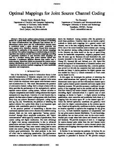
Consider a common two-way relay channel (TWRC) as shown in Fig.1, where two single-antenna end nodes N1 and N 2 exchange information with the assistance of the relay node
N 3 . In our system, Si ∈ {0,1}
k
denotes the length- k
uncoded binary packet of node N i . After channel encoding, we get the length- n encoded packet X i ∈ {0,1}n . In this paper, we use the quadrature phase-shift keying (QPSK) modulation, so the coded packet is mapped to the transmitted packet as n2 Ai ∈ {1 + i,1 − i, −1 + i, −1 − i} . The received noisy packet can be denoted as Y= Ai + Wi , in which N i is the Gaussian noise i at the node N i . In addition, we use the lower case letters,
si ∈ {0,1} ,
xi ∈ {0,1} ,
ai ∈ {1 + i,1 − i, −1 + i, −1 − i}
and
yi ∈ R , to denote the source bit, channel encoded bit, QPSK modulated symbol and noise-polluted symbol in the corresponding packets, respectively. Note that the rate of the channel code is = R k n < 1 . We assume that each end node uses the same encoder in this paper.
Uplink phase
III. BICM FRAMEWORK FOR PNC
N2
N1
This section shows more details about the encoding/decoding process dealing with PNC in TWRC system. We will first make a brief introduction of the framework in BICM encoder, which will be performed in both end nodes. After that, we elaborate the process at the relay node, which performs as an Iterative Demapping and decoding scheme.
X2
X1 N3
Downlink phase
X1 ⊕ X 2 N1
As described above, the downlink processing in PNC is trivial while the uplink CNC processing, computing S3 from Y3 through channel decoding and PNC mapping [7], is the key. In this paper, we concentrate on the CNC process at the relay node with the QPSK mapping.
X1 ⊕ X 2 N2
A. Channel encoding model
t
Decoding process Encoding process
Fig. 1. Two-way relay channel transmission model
Si
In this paper, we do not consider the direct link between the two end nodes due to the long distance. As a result, the communication between N1 and N 2 can only be achieved through the relay node. What is more, considering the huge interference difference between transmitted signal and received signal at one node in real situation, all nodes are assumed to work in the half-duplex mode as in real wireless systems. Based on the two assumptions, at least two phases are needed to finish the information exchange between the two end nodes, which are the uplink phase and the downlink phase, as shown in Fig. 1. In the uplink phase, both the two end nodes transmit simultaneously to the relay node. Here, we also assume the two transmitted signals arrive at the relay node at a signal level synchronization 1 . Then we get the superimposed symbol at the relay node, which is expressed as:
y3 = a1 + a2 + w3
(1)
where w3 is the additive white Gaussian noise (AWGN) with variance σ 2 , ai is the QPSK modulated symbol sent from node N i . The task of relay node is to compute the network coded (NC) packet S3 in the physical layer [1], i.e., try to generate S= S1 ⊕ S 2 from the received packet Y3 . 3 In the downlink phase, the relay node will first channel encode S3 into X 3 and then modulated it into A3 before finally broadcasting it to both end nodes. Once the end nodes receive A3 , they can use the standard demapping and decoding process to obtain the network coded packet S3 . Then, the end nodes can recover the target information with the help of their self-information as S= S 2 ⊕ S3 and 1
S= S1 ⊕ S3 . 2
. . .
Variable node
Our paper focuses on the channel decoding. In fact, the asynchronized signal can be pre-transformed to the synchronized form before the decoding.
Π2
Π1 . . . Check node
. . .
. . .
mapper . . .
Accumulator
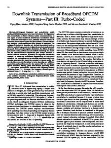
Fig. 2. Tanner graph of regular RA code with rate=1/3 = ( dv
3,= d c 1 ),
where the square elements denote the check node and the circular elements denote the variable in the Tanner graph. Note that, the encoding operation based on the Tanner Graph could be read from left to right, while the decoding operation is from right to left.
At the two end nodes, the repeat-accumulate (RA) code [16], as the Tanner graph depicted in Fig. 2, is used. Consider the encoding process by reading Fig. 2 from left to right. The source N i first produces a raw binary source packet Si . After repetition process at the left-most variable node, the binary packet is interleaved by Π1 and modulo-2 added at the check node, which is similar to the LDPC code 2. The difference in the construction between RA code and LDPC code is the accumulator (ACC). We can decompose the ACC to be a concatenation of check nodes and variable nodes (VND) in the tanner graph, as shown in the dashed rectangle of Fig. 2. The ACC works as a differential encoder to create the connection between two adjacent check node. After the ACC, another bit-interleaver Π 2 helps to make the RA code more robust [17], which is actually indispensable in the BICM iterative decoding [13]. Then we get the encoded packet X i , the QPSK mapper translates X i to the modulated packet Ai before the transmission. 2
1
Ai
Xi
As we only consider simple regular RA code with the degree-one check node (CND), the check node just pass the received message without modulo-2 addition.
B. Iterative demapping and decoding In this part, we try to explain the iterative process between demapping and decoding at the relay node. We will first introduce the general iterative framework by regarding the demapper and decoder as two separated modules. After that, we present the detailed implementation of the iteration process, which redesigns the inner iteration and out iteration to improve the performance. PNC mapping
Channel decoding
LMD ,e LDM ,a
−1 PP 2 2
LAC ,a
LMD ,a
ACC LDM ,e
LCV ,e
CND LCA,e
−1 PP 1 1
LVC ,a
LCV ,a
Fig. 3. Decoder model at the relay node
Pr ( x3,1 , x3,2 = 10 | y3 ) + Pr ( x3,1 , x3,2 = 11| y3 )
(2)
Pr ( x3,1 , x3,2 = 00 | y3 ) + Pr ( x3,1 , x3,2 = 01| y3 )
With the Bayes' rule P= ( A | B ) P ( B | A) ⋅ P ( A) P ( B ) , we get Pr= ( x3,1 x3,2 | y3 ) Pr ( y3 | x3,1 x3,2 ) ⋅ Pr ( x3,1 x3,2 ) Pr ( y3 ) .
Pr( y3 | x3,1 x3,2 = 10) + Pr ( y3 | x3,1 x3,2 = 11) ⋅ exp LAM , a ( x3,2 ) = LAM , a ( x3,1 ) + ln Pr( y3 | x3,1 x3,2 = 00) + Pr ( y3 | x3,1 x3,2 = 01) ⋅ exp LAM , a ( x3,2 )
Different from the straightforward process of CNC2 [7], we propose an iterative demapping and decoding framework as in Fig. 3(a). The traditional CNC2 only takes the iteration in the decoding process while the scheme we proposed takes the iteration in both demapping and decoding process. In particular, the channel decoded soft symbols are feedback to the demapper to obtain a better demodulated symbol, which provides extrinsic information to improve the decoding performance. We now elaborate the detailed iterative decoding processing as shown in Fig. 3(b). As in the figure, the decoding system is disassembled into four components: Demapper, ACC, CND and VND. The log-likelihood ratios (L-values or LLRs) of the extrinsic (e) message passed from the demapper (M) to the ACC (A) is denoted as LMA, e . Similarly, LAC , e is from ACC to CND (C) and LCV , e is from CND to VND (V). Note that every extrinsic message is the a-priori message for the next component, so LMA, e is LMA, a , LCV , e is LCV , a . Demapping Processing: We first introduce the demapper, which transforms the received signals to the soft message LMA, e , i.e. the extrinsic message about the confidential of X 1 ⊕ X 2 . As required in the iterative CNC2, the demapper needs to calculate the L-value of every network coded bit by using the channel output y3 and the feedback message LAM , a . For each QPSK symbol ai , the two bits modulated to it is denoted by i ,1
Pr ( x3,1 = 0 | y3 )
L ( x3,1 | y3 , LAM , a )
VND LVC ,e
(b) Soft message passing in decoding process
(x
= ln
Pr ( x3,1 = 1| y3 )
Due to the random bit-wise interleaver Π 2 , the two bits x3,1 and x3,2 can be regarded as independent with each other. Then we can rewrite (2) as
(a) Iterative CNC2
Demapper
L ( x3,1 | y3 ) = ln
, xi ,2 ) . So, at the demapper, the L-value of bit x3,1
conditioned on the received symbol y3 can be calculated as
where LAM , a ( x3,2 ) = ln
Pr ( x3,2 = 1)
Pr ( x3,2 = 0 )
(3)
is the a-priori message
of x3,2 , and its initial value is zero, which means there is no a-priori knowledge about the coded bits yet. Finally, the
extrinsic information can be obtained by subtracting the a-priori information as LMA, e= ( x3,1 | y3 , LAM ,a ) L ( x3,1 | y3 , LAM ,a ) − LAM ,a ( x3,1 ) = ln
Pr ( y3 | x3,1 x3,2 = 10 ) + Pr ( y3 | x3,1 x3,2 = 11) ⋅ exp LAM , a ( x3,2 ) Pr ( y3 | x3,1 x3,2 = 00 ) + Pr ( y3 | x3,1 x3,2 = 01) ⋅ exp LAM , a ( x3,2 )
(4)
Decoding Processing: We then introduce the signal processing in the decoder. After de-interleaving LMA, e , the channel decoder performs the traditional RA iterative decoding process by passing the soft message through ACC decoder, CND and the VND in a successive way. In the Tanner graph of Fig. 2, the output extrinsic message associated to an output edge- i on a check node p can be expressed as Pr ( x p = 1) = Li , e ( x p ) ln= ln Pr ( x p = 0 )
1 − exp j ,in L j ,in j ≠ i 1 + exp L
1− ∏
1 − exp j ,in 1+ ∏ L j ,in j ≠ i 1 + exp L
(5)
where L j ,in represents the incoming message associated to edge- j . For a variable node q , the output extrinsic message of edge- i can be computed as (4). Pr ( xq = 1) = Li , e ( xq ) ln= Pr ( xq = 0 )
∑L j ≠i
j , in
(6)
Inner iteration and out iteration: The iteration between demapper and the decoder is shown in Fig. 3(b). The demapper, the ACC and the CND forms a
single unit. The iterative processing is first performed within this unit and it is referred to as the inner iteration. The purpose of the inner iteration is to adequately infuse the a-priori knowledge LVC , a [18]. The out iteration will then be taken between the Inner iteration and the VND. In this paper, three inner iteration is performed in each out iteration. IV. MAPPING DESIGN BASED ON EXIT CHART
00
(10)
10
As proved in [19] [20], the symbol-wise mutual information I ( a3 ; y3 ) is independent of the mapping mechanism. With the chain rule of mutual information [21], the mapping only influences the partitioning of the total amount of bit-wise mutual information I ( x3 ; y3 ) . Although the mapping scheme cannot increase the total mutual information, the selection of mapping scheme can affect the performance of decoding algorithm with iteration. We focus on the impacts of different mapping schemes in our proposed iterative CNC2. We consider QPSK mapping in iterative CNC2 model. Each QPSK mapping scheme shown in Fig. 4 contains a traditional QPSK mapping and the corresponding PNC QPSK mapping. Note that the hollow mapping is applied at the end nodes and solid mapping is applied at the relay node. We can easily find that the PNC QPSK mapping is many point to one sequence mapping (when detection), which is unlike the traditional constellation. For example, the binary sequence x3,1 x3,2 = 00 could correspond to four constellation points in
00
00
11
10
10
00
00
Gray mapping
=
∑
(
ai ≡ x3,1 x3,2
)
∑
(
ai ≡ x3,1 x3,2
Pr ( ai ) ⋅
1 2pσ
)
1
2 2σ
2
y3 − ai
10 (01)
11
00
anti-Gray mapping
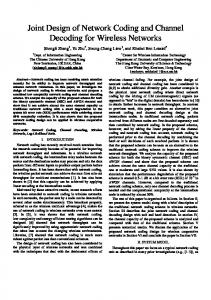
There are two different mappings for QPSK modulation, Gray mapping (GM) and anti-Gray mapping (AGM). One visual difference between such two mapping schemes is the hamming distance distribution, either the traditional QPSK mapping or the PNC mapping, as shown in Fig. 4. Similar to the work done in [20], we draw the EXIT charts of the two mapping schemes, as given in Fig. 5, where I A is the prior input to the demapper, I E is the extrinsic output of the demapper. Obviously, the prior message makes little sense to the demapper in Gray mapping, which means when considering the iterative framework with Gray mapping, the performance nearly has no improvement for iterations. But when the anti-Gray mapping is employed, the iterative framework could utilize the feedback message to get a better output for the subsequent channel decoder. The I E of Gray mapping is higher than that of anti-Gray mapping before the cross point, and after the cross point the former is lower than the latter. That means the anti-Gray mapping can only outperforms the Gray mapping at the higher I A , i.e., only when the feedback message is good enough. Therefore, as the iteration goes, the anti-Gray mapping scheme works better than the Gray mapping in our iterative framework.
Pr ( ai ) ⋅ Pr ( y3 | ai )
exp − 2
01
Fig. 4. Superimposed Constellations of Two QPSK Signals in CNC2, the hollow constellation points denote the QPSK modulation of one node and solid ones denote the superimposed QPSK modulation. Every solid constellation point is the physical addiction of two hollow constellation points.
Fig. 4. Because of this special character, the PDF of the y3 will be a sum form as
Pr= ( y3 | x3,1 x3,2 )
00
(11)
(10)
(01)
01
11
(00)
(11)
(00)
00
In traditional decoding, the demapping and decoding processes are separated. Then the Gray mapping performs best by minimizing the detection BER. However, in BICM receiver, non-Gray mapping may performs better by providing extrinsic information in the iterations. Therefore, mapping design is an important problem in BICM systems. When PNC is considered, the mapping design is more complicated since the constellation at the relay node is a superimposed one of the two constellations at the transmitters. This section will use the EXIT chart to analysis the mapping design on the performance of the proposed BICM scheme.
01
(7)
Fig. 5. EXIT charts of two demappers at SNR=4dB
When considering the whole decoding system at the relay node, i.e., concatenating the demapper and decoder, we can draw the EXIT chart to reveal the convergence character of the decoding scheme. For contrast, we draw the EXIT curves for the inner iteration with different mapping schemes and the VND. Fig. 6 shows us three EXIT curves of a regular RA code with R = 1 3 at Eb N 0 = 1.8dB , the upper two are the EXIT curves of inner iteration, the lowest one is for the VND. We can easily find that in such case, the curve of both AGM and GM stays above the curve of VND, which indicates that either mapping scheme could correctly recover the network coded data from the received signal. We also notice that before the cross point the GM works better than the AGM, but as the iteration goes, AGM outperforms GM after the cross point.
In Fig. 8, we investigate the impact of packet length (2048 and 4096 bits) to the BER performance of the iterative CNC2 decoding scheme with anti-Gray mapping and Gray mapping under different SNR. The result shows that the longer packet length is, the better performance it will get.
Fig. 7. BER performance of iterative CNC2 and traditional CNC2 under different mapping schemes.
Fig. 6. EXIT curves of AGM and GM for an regular RA code with R at
=1 3
Eb N 0 = 1.8dB V.
NUMERICAL SIMULATION
In this section, we investigate the BER performance of the above iterative decoding scheme. We employ the regular RA code with R = 1 3 in our simulations. The noise is AWGN with variance σ 2 and the SNR is defined as 2 σ 2 (the average power of one end node is 2 as we use the QPSK modulation). We calculate the BER with the decoded packet S3 and the network coded genetic packet S1 ⊕ S 2 . In Fig. 7, we show the BER performance of iterative CNC2 and the traditional CNC2 under the two mapping schemes that we consider above. In the simulation, the uncoded packet length is set to 4096 and the BER is calculated over 1000 packets, with 20 iterations in the decoding algorithm. The result shows without the iteration between demapper and channel decoder, the anti-Gray mapping scheme performs badly, but the iteration included the demapper nearly has no effect to the Gray mapping scheme. That means the demapper iteration is very important to the anti-Gray mapping, but not to the Gray mapping. The anti-Gray mapping can outperform the Gray mapping quickly as the SNR increase. .
Fig. 8. BER performance of AGM and GM with different packet length.
VI. CONCLUSION In this paper, we have proposed an iterative demapping and decoding framework at the relay node in TWRC with PNC. The EXIT chart is used to study the convergence behavior of the decoding scheme. We found that under such decoding system, the anti-Gray mapping scheme outperforms the Gray mapping significantly. ACKNOWLEDGEMENT This paper is partially supported by NSFC (No. 61372078, 60602066, and 60773203) and supported by Foundation of Shenzhen City (No. JC201005250034A , JCYJ20120613174214967,
JC201005280404A, JC200903120069A and SG200810220145A).
Prof. Qian is the corresponding author.
REFERENCES [1] S. Zhang, S. C. Liew, and P. P. Lam, "Hot topic: physical layer network coding", Proc. 12th Annual International Conference on Mobile Computing and Networking (MobiCom), pp. 358-365, Los Angeles, California, USA, Sept 2006 [2] R.Ahlswede, N.Cai, S.-Y. R. Li, and R.W. Yeung, "Network information flow", IEEE Trans. on Information theory, vol. 46, no. 4, pp. 1204-1216, Jul 2000. [3] S.-Y. R. Li, R.W. Yeung and N.Cai, "Linear Network Coding", IEEE Trans. Inform. Theory, vol. 49, no.2, pp. 1204-1216, Feb 2003. [4] Nam, Wooseok, Sae-Young Chung, and Yong H. Lee. "Capacity of the Gaussian Two-Way Relay Channel to Within 1/2 Bit." Information Theory, IEEE Transactions on 56.11 (2010): 5488-5494. [5] Zhang, Shengli, Liew S C, Wang H, et al. "Capacity of two-way relay channel." Access Networks. Springer Berlin Heidelberg, 2010. 219-231. [6] Zhang, Shengli, and Soung Chang Liew. "Applying physical-layer network coding in wireless networks." EURASIP Journal on Wireless Communications and Networking 2010 (2010): 1. [7] S. Zhang, S. C. Liew, "Channel Coding and Decoding in a Relay System Operated with Physical-Layer Network Coding", in IEEE Journal of selected areas in communication (JSAC ), vol. 27, no. 5, pp. 788-796, June 2009. [8] Liu, Jianquan, Meixia Tao, and Youyun Xu. "Pairwise check decoding for LDPC coded two-way relay block fading channels." Communications, IEEE Transactions on 60.8 (2012): 2065-2076. [9] Wubben, D., and Yidong Lang. "Generalized sum-product algorithm for joint channel decoding and physical-layer network coding in two-way relay systems." Global Telecommunications Conference (GLOBECOM 2010), 2010 IEEE. IEEE, 2010. [10] T. Huang, T. Yang, Jinhong Yuan and Ingmar Land, “Convergence Analysis for Channel-coded Physical Layer Network Coding in Gaussian Two-way Relay Channel,” Proc. 8th International Symposium on Wireless Communication Systems (ISWCS), pp. 849-853, Aachen, Germany, Nov. 2011. [11] E. Zehavi, "8-PSK trellis codes for a rayleigh channel", IEEE Trans.Commun., vol. 40, pp. 873–884, May 1992. [12] Giuseppe Caire, Giorgio Taricco, Ezio Biglieri, "Bit-Interleaved Coded Modulation", IEEE Trans. Inform. Theory, vol. 44, no. 3, pp. 927-946, May 1998. [13] X. Li, James A. Ritcey, "Bit-Interleaved Coded Modulation with Iterative Decoding", IEEE Trans. Commun., vol. 1, no. 6, pp. 169-171, Nov 1997. [14] A. Chindapol and A. Ritcey, "Design, analysis and performance evaluation for BICM-ID with square QAM constellations in Rayleigh fading channels," IEEE Journal on Selected Areas in Communications, vol. 19, pp. 944-957, May 2001. [15] A. Ashikhmin, G. Kramer, and S. ten Brink, "Extrinsic information transfer functions: Model and erasure channel properties," IEEE Trans. Inf. Theory, vol. 50, no. 11, pp. 2657–2673, Nov 2004. [16] D. Divsalar, H. Jin, and R. J. McEliece, "Coding theorems for 'turbo-like' codes," in Proc. 36th Annu. Allerton Conf. Commun., Control, Computing, Sept. 1998, pp. 201–210. [17] D. Divsalar, S. Dolinar, and F. Pollara, "Serial concatenated trellis coded modulation with inner rate-1 accumulate code," in Proc. IEEE Global Telecommun. Conf., San Antonio, TX, vol. 2, pp. 936–940, Nov. 2001. [18] S. ten Brink and G. Kramer, "Design of repeat-accumulate codes for iterative detection and decoding," IEEE Trans. Signal Process., vol. 51,no. 11, pp. 2764-2772, Nov. 2003. [19] S. ten Brink, J. Speidel, and R. Yan, "Iterative demapping and decoding for multilevel modulation," in Proc. IEEE Globecom, Sydney, Australia, Nov. 1998, pp. 579–584.
[20] S. ten Brink, "Designing iterative decoding schemes with the extrinsic information transfer chart," AEÜ, Arch. Elektron. Ü,bertragung., vol. 54, no. 6, pp.389 -398, Dec. 2000. [21] Cover. T. M.; Thomas. J. A., "Elements of Information Theory". New York: Wiley, 1991.