Mapping Irregular Algorithms in a Custom Computing Image Processing Framework F. Planque, I. C. Kraljic, Y. Savaria MiroTech Microsystems Inc. 395 Ste-Croix suite 202 St-Laurent, Qc H4N 2L3 Canada
[email protected]
Abstract A real-time image processing framework based on reconfigurable computing and the hardwired dataflow paradigm was proposed [1]. Operations are defined at the level of basic image processing primitives (convolution, noise filtering...). Each operation is implemented as one physical operator that can be mapped in reconfigurable logic. All operators are encapsulated and present uniform interfaces for data and control. Cascading operators for parallel execution is straightforward. A hardware core library that contains 50+ basic operators (n x n convolutions, median, histogram, noise filtering, FIRs, FFTs, morphology operations...) has been developed. The paper aims at showing how complex irregular algorithms can be adapted for implementation on the dataflow framework. The mapping of connected components labeling and image warping are considered.
Median
Sub Operation
Data dependency
Dataflow graph
Median operator
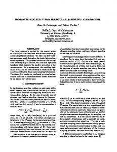
I. IMAGE PROCESSING FRAMEWORK Real-world image processing applications are often composed of concatenated (cascaded) basic operators such as convolver, median filter, histogrammer, etc. Data streams physically flow through these concatenated operators (wired dataflow paradigm; Figure 1) and all the operations are executed sequentially on each pixel (multiple instructions single data, or MISD, paradigm). This model is well-adapted to a large class of RTIP applications [2]. A framework to address real time image processing is based on reconfigurable computing and the wired dataflow paradigm [1]. A typical reconfigurable computing platform leverages large field-programmable gate arrays (FPGAs) to attain the processing efficiency of application-specific integrated circuits (ASICs) while retaining the plasticity of software.
Edge
Edge detector
Subtraction operator Physical operator
Physical connection
Operator graph
Figure 1: Wired dataflow paradigm.
The granularity of the framework is at the level of basic image processing operators: convolver, filter, histogrammer. This level is intermediate between registertransfer level (adders, multipliers, registers) and application level, and for FPGA implementation, it is a good trade-off. A real-world application is thus a combination of RTIPlevel operators. The framework is: !
Planque, Kraljic, Savaria
Uniform: All the operators are encapsulated and present uniform interfaces for control. Control of an operator consists in setting specific parameters of the operator, e.g. a convolution kernel. A single configuration controller interfaces externally to a FIFO. P17
!
Modular: Inputs and outputs of operators are designed so that operators can be cascaded transparently and without overhead. A major feature of cascade operators is that the time required to process one image does not increase when more operators are added, since operators are executed in parallel (latency is affected though). Currently, operator concatenation is done manually.
!
Scalable: As well as operators can be concatenated, reconfigurable boards can be cascaded for implementing especially large applications.
!
Adaptive: The operators can be reconfigured to adapt to different image sizes and pixel resolutions. Thanks to FPGA technology, even an exotic configuration (such as e.g. 654x567x43 Hz image and 3-bit pixels) will be implemented as efficiently as a standard configuration.
!
(First pass) Input binary image 0 0 0 0 0 0 0 0 0 0 0 0 0 0 0 0 0 0
0 1 1 1 1 1 1 1 1 1 1 1 1 1 1 1 1 0
II. CONNECTED COMPONENTS LABELING Connected components labeling (CCL) is an essential operation for blob analysis and target recognition types of applications. CCL is a grouping operation that assigns the same unique label to all groups of connected “foreground” pixels (blobs). Due to its complex control and memory intensive architecture, the labeling is a good candidate to demonstrate mapping of irregular algorithms.
Planque, Kraljic, Savaria
0 1 0 1 1 0 1 1 1 1 1 1 0 0 0 0 1 0
0 1 0 1 1 1 1 1 1 1 1 1 0 0 0 0 1 0
0 1 0 0 0 1 1 1 1 1 1 0 0 1 1 0 1 0
0 1 0 0 0 0 0 1 1 0 0 0 0 1 1 0 1 0
0 1 0 0 0 0 0 0 0 0 0 0 0 0 0 0 1 0
Temporary labels
0 1 1 1 1 1 1 1 1 1 1 1 1 1 1 1 1 0
0 0 0 0 0 0 0 0 0 0 0 0 0 0 0 0 0 0
0 0 0 0 0 0 0 0 0 0 0 0 0 0 0 0 0 0
0 1 1 1 1 1 1 1 1 1 1 1 1 1 1 1 1 0
0 1 0 0 0 0 0 0 0 0 0 0 0 0 0 0 1 0
0 1 0 2 2 0 3 3 0 0 4 4 0 0 0 0 1 0
0 1 0 2 2 0 3 3 3 3 3 3 0 0 0 0 1 0
0 1 0 2 2 2 2 2 2 2 2 2 0 0 0 0 1 0
0 1 0 0 0 2 2 2 2 2 2 0 0 5 5 0 1 0
0 1 0 0 0 0 0 2 2 0 0 0 0 5 5 0 1 0
0 1 0 0 0 0 0 0 0 0 0 0 0 0 0 0 1 0
0 1 1 1 1 1 1 1 1 1 1 1 1 1 1 1 1 0
0 0 0 0 0 0 0 0 0 0 0 0 0 0 0 0 0 0
Equivalence table {3 " 2, 4 " 3}
(Labeled image) 0 0 0 0 0 0 0 0 0 0 0 0 0 0 0 0 0 0
0 1 1 1 1 1 1 1 1 1 1 1 1 1 1 1 1 0
0 1 0 0 0 0 0 0 0 0 0 0 0 0 0 0 1 0
0 1 0 2 2 0 2 2 0 0 2 2 0 0 0 0 1 0
0 1 0 2 2 0 2 2 2 2 2 2 0 0 0 0 1 0
0 1 0 2 2 2 2 2 2 2 2 2 0 0 0 0 1 0
0 1 0 0 0 2 2 2 2 2 2 0 0 5 5 0 1 0
0 1 0 0 0 0 0 2 2 0 0 0 0 5 5 0 1 0
0 1 0 0 0 0 0 0 0 0 0 0 0 0 0 0 1 0
0 1 1 1 1 1 1 1 1 1 1 1 1 1 1 1 1 0
0 0 0 0 0 0 0 0 0 0 0 0 0 0 0 0 0 0
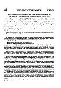
Figure 2: Two-pass connected components labeling.
The two-pass algorithm is based on an L-type mask, where the current pixel and its left and top neighbors are considered (4-connectivity). The first pass performs a leftto-right, top-to-bottom label propagation. The algorithm is: If current pixel Px,y is in foreground: !
If current pixel Px,y has no top Px,y-1 and left Px-1,y neighbors, create a new label and assign it to that pixel.
!
If current pixel has only one labeled neighbor, give it the same label.
!
If current pixel has two neighbors with the same label, give it that label.
!
If current pixel has two neighbors with different labels, assign the minimum of the two labels to the current pixel and register in an equivalence table that the labels are equivalent.
A. Algorithm A classical two-pass algorithm [3] has been selected for implementation in the reconfigurable dataflow framework (Figure 2). Actually, a version of this algorithm was successfully implemented on a wired dataflow machine (the 1024-processor Dataflow Functional Computer) [4].
0 1 0 1 1 0 1 1 0 0 1 1 0 0 0 0 1 0
Second pass
Open: The use of reconfigurable computing as a target system allows a user to implement any applicationspecific or proprietary operator that is not available in the library. This new operator should feature the framework's standard interfaces, and could then be used as any other existing operator.
A library of cores designed in the RTIP framework was developed; it contains 50+ basic operators (n x n convolutions, median, histogram, noise filtering, FIRs, FFTs, mathematical morphology operations...). The library is being enhanced with higher-complexity operators, such as connected components labeling (section II) and image warping (section III).
0 1 0 0 0 0 0 0 0 0 0 0 0 0 0 0 1 0
At the end of the first pass, the equivalence classes must be determined from all pairs of equivalent labels stored in the equivalence table. Then, a unique label is assigned to each equivalence class. Finally, the second pass rescans the image of temporary labels and replaces each temporary label with its final unique label.
P17
B. Memory architectures for equivalence resolution Availability of content-addressable memories (CAMs) greatly simplifies implementation in hardware of a module to resolve equivalence classes. Without going into implementation details, a CAM allows to find all labels equivalent to a specific label in a single cycle (O(n) complexity, where n is the number of equivalent pairs). Not only is the implementation of equivalence resolution simplified, but its performance is also greatly improved. State-of-the-art Xilinx Virtex FPGAs have support for CAMs; however their size is small (a 4 kbit block RAM can implement a 16x8 CAM) [5]. A mid-range Virtex 1000 (1M gate equivalent) does not have enough block RAMs to implement a usable equivalence resolution engine. Standard memories were thus used in the labeler, with a depth-first search procedure for repeatedly scanning the table of equivalent labels. Memory consumption is lower than with a CAM implementation; however execution time is longer (O(n2) complexity).
Even/odd image
Even/odd image
Images 2, 4, 6…
Odd labeler Switch
Images 1, 3, 5…
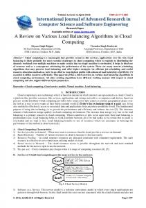
The connected components labeling core is decomposed as a cascade of RTIP-compatible cores. A standard library frame delay is used to store the image of temporary labels. The first pass algorithm was implemented as a stand-alone framework-compatible core, as well as the second pass algorithm. The equivalence resolution is also autonomous. This modular approach ensures an easy path to future upgrades of any of the three algorithmic components (first pass, equivalence resolution, second pass).
Mux
Equivalence resolution
1st pass
2nd pass
Frame delay
C. Architecture Internally, the hardwired dataflow model is broken to allow efficient processing; however, at the operator level, the model is restored. Hence, the labeler is fully compatible with other framework cores as it presents the same uniform interfaces.
Labeled image stream
Even labeler
Image stream
RTIP framework compatible I/O Custom I/O
Figure 3: On-the-fly connected components labeler.
Image stream Image 1
Image 2
Image 3
Image 4
Odd labeler 1:Pass1
1:Resol
1:Pass2
3:Resol
3:Pass1
One single instance of the labeler will not sustain onthe-fly processing. A straightforward, albeit non optimal, on-the-fly version uses two instances of the labeler in a classical “ping-pong” architecture, where instance #1 processes only the odd images, and instance #2 processes only even images (Figures 3 and 4).
Even labeler 2:Pass1
2:Resol
2:Pass2 4:Pass1
n: Pass1 first pass on image n n: Resol equivalence resolution on image n n: Pass2 second pass on image n
Figure 4: Parallelism for on-the-fly processing
D. Limitations A labeler has been implemented and validated on a 30 frames/sec. image stream. It is limited to 254 temporary labels and 254 final labels. (Label 255 is used for optional discarding of blobs that touch the image borders.) Up-to Planque, Kraljic, Savaria
P17
512 equivalent pairs of labels can be managed. Upgrading to higher label counts is straightforward. The core uses half of a Virtex XCV300 and can process 50 Mpixels/second. Several add-on cores for the labeler have been developed: area, bounding box and center of gravity. Refering to Figure 4, it appears that pass 1, pass 2 and equivalence resolution are executed in parallel. Equivalence resolution must end before a new image is input to the labeler, otherwise on-the-fly execution will fail. The worst case execution time for resolving the equivalence classes is Nequ x Nequ – 1, where Nequ is the number of equivalent pairs that can be stored (in the equivalence table). The worst case execution time for the first pass is X x Y, where X, Y are respectively the width and height of the input images. Hence, on-the-fly processing is guaranteed if and only if X x Y ≥ Nequ x Nequ – 1 (Figure 5). Since the labeler supports 512 equivalent pairs, the image size for on-the-fly processing must be at least 512x511. Lower image sizes may violate the on-the-fly constraint. On-the-fly processing: Correct Nequ x (Nequ – 1)
1st pass image 1
Equiv. Res. image 1
Image 3
a 2,1 a 2, 2 a 2,3
0 0 1
[u, v] coordinates
Affine transformation
Warped pixels
Figure 6: Architecture of an inverse-mapping warper As with the labeler, the image warper is fully framework-compatible; a two-instance ping-pong implementation is required for on-the-fly processing. A core for image rotation was implemented for validation purposes. The nearest-neighbor interpolation scheme allows a 1:1 ratio on input/output throughputs (one pixel in, one pixel out).
On-the-fly processing: Failed Nequ x (Nequ – 1)
Equiv. Res. image 1
Image 3
XxY
Figure 5: On-the-fly processing constraints
III. IMAGE WARPING Image warping is another algorithm whose implementation in a wired dataflow is not immediate. Both Planque, Kraljic, Savaria
a1,1 [x, y,1] = [u, v,1]× a 2,1 a 3,1
Frame buffer
XxY
1st pass image 2
The inverse mapping algorithm was selected as a case study. More specifically, the class of affine transformations with nearest-neighbor interpolation was targeted. Affine transformations are defined by:
The architecture of the warper is given in Figure 6.
1st pass image 2
1st pass image 1
“inverse mapping” and “forward mapping” algorithms [6] can be adapted to a dataflow execution mode. Given an input image with pixel coordinates {u, v} and a warped image with pixel coordinates {x, y}, forward mapping defines two functions F and G: {x, y} = {F(u, v), G(u, v)}. Inverse mapping defines H, K such that: {u, v} = {H(x, y), K(x, y)}. From an implementation point of view, the forward mapping algorithm scans the input image in a leftto-right, top-to-bottom fashion, and generates arbitrary coordinates for output pixels. The inverse mapping algorithm generates the warped image in a scanline fashion, and reads input pixels in an arbitrary way (i.e. dependent on functions H and K).
The core could be adapted for higher-order interpolation schemes (bilinear, bicubic). However, performance would severely degrade since computing one output (warped) pixel requires several reads in the frame buffer. A better approach would be to implement the forward mapping algorithm, which would support efficient high-order interpolation. Indeed, with this scheme, a neighborhood can be generated on the fly from the input image, and all pixels required for interpolating one warped pixel can be accessed in a single cycle. As a demonstration of the cascading property of framework cores, a blob analysis front-end core could be implemented with the rotation and labeling cores (Figure 7). P17
Centroid Rotation
Bin
CCL
Area Bound box
Angle
Threshold
Figure 7: Cascaded core for blob analysis front-end
IV. CONCLUSION Two irregular algorithms were successfully implemented to demonstrate how a reconfigurable computing image processing framework can be used to support a wide range of useful image processing algorithms. The connected components labeling is a first version aimed at demonstrating the feasibility of the concept. Enhancements to this core, such as adding support for more equivalent pairs of labels, or greater number of labels are straightforward. More complex optimizations would involve improving the first pass of CCL in order to lower the complexity of equivalence resolution, see e.g. [4]. A higher performance CAM implementation is also feasible on the largest 2M+ gate FPGAs. The second core, that implements inverse-mapping rotation, can be improved for higher-order interpolation schemes, however performance would be significantly diminished. Forward mapping was found more suitable for implementing these complex interpolations.
REFERENCES [1] N. Belanger, I. Kraljic, Y. Savaria, “A ReconfigurableComputing Real-Time Image Processing Framework”, Third Annual Workshop on High Performance Embedded Computing HPEC'99. [2] G.M. Quenot, C. Coutelle, J. Serot, B. Zavidovique, “Implementing image processing applications on a real-time architecture”, Computer Architectures for Machine Perception CAMP'93. [3] R. M. Haralick, L. G. Shapiro, Computer and Robot Vision, Vol. I, Addison-Wesley, 1992. [4] S. Praud. “Mapping of Connected Component Labeling on the Dataflow Functional Computer”, Master thesis, Universite d'Orsay - Paris XI, France, June 1993 (in French). [5] J.-L. Brelet, “Using Block RAM for High Performance Read/Write CAMs”, Xilinx App. Note XAPP204 (v1.2) May 2, 2000. [6] G. Wolberg, Digital Image Warping, IEEE Computer Society Press, 1990.
Planque, Kraljic, Savaria
P17