describe requirements on and properties of software arte- facts, as .... experiences with building tailor-made run-time platforms from generic components. Requirements on such a plat- form are posed by the application that is envisioned to be.
Mapping Requirements to Reusable Components using Design Spaces* L. Baum, M. Becker, L. Geyer, G. Molter System Software Research Group University of Kaiserslautern D-67653 Kaiserslautern, Germany {lbaum, mbecker, geyer, molter}@informatik.uni-kl.de
Abstract A consistent implementation of component-based reuse bears several implications for the design of the software development process. For instance, requirements engineering has to be tailored to particularly elicit information necessary for selecting and configuring appropriate components. Besides sketching our approach to component-based system development, this paper shows how Design Spaces can be applied to actively support reuseoriented activities. Design Spaces allow to uniformly describe requirements on and properties of software artefacts, as well as correlations between specific properties. As a consequence, they are well suited to guide the requirements capturing towards the properties of existing components, and to map those requirements to component selections and configurations. The paper demonstrates how to consistently deploy the Design Space technique throughout the process, leading to a complete and strongly tool-supported path from requirements capturing to system implementation.
1. Introduction The highly competitive and dynamic field of software development creates a constant motivation for organizations to increase the efficiency of their development processes. Software reuse and especially the component paradigm are commonly recognized as approaches to achieve this goal. However, there are still inherent problems with both techniques. On the product side, software components have to be made sufficiently abstract to be reusable, while at the same time need to be sufficiently concrete to be of any use at all. On the process side, there are the problems of finding best-fitting components in the reuse pool, and of integrating selected components into one system while considering component interdependencies and architectural constraints. We have developed an approach to component-based *This research was supported by the Deutsche Forschungsgemeinschaft as part of the Special Research Project 501.
and reuse-oriented system development that addresses these typical problems. The flexibility of reusable products is achieved by using generic components, and the overall development process is tailored to specifically support software reuse. A consistent implementation of the component-based development paradigm thereby affects the entire development process from requirements capturing to component configuration. The requirements engineering step, for instance, has to be adapted to particularly elicit information relevant for reuse activities. Similarly, the subsequent process steps have to be designed to select and configure a suitable set of software components. With the concept of extended Design Spaces, we present a semiformal technique to uniformly support these reuse-oriented activities throughout the overall process, leading to a complete path from requirements capturing to component selection and configuration. In this paper, we will illustrate the consequences for the respective process steps and demonstrate how this path can strongly be supported by tools. For the remainder of this paper, our examples will be oriented at the construction of customized run-time platforms for embedded control systems. This restricted domain is characterized by well-understood abstractions and a known degree of variability – properties being especially beneficial to software reuse. However, the presented approach should as well be applicable to any other, similarly restricted domain. The basic prerequisite is that a known and manageable set of component variants is likely to cover the vast majority of possible requirements. In order to set the scene, the following section will give a brief overview of our component-based development process. It will furthermore touch on some concepts that are fundamental to our process. This concerns the topics of generic components, software architecture, and the use of a uniform domain model throughout the process. Section 3 introduces extended Design Spaces that are our technique of choice to describe important parts of the domain model. Sections 4 and 5 then show how to deploy the Design Space technique during requirements capturing as well as during system design, i.e., architecture selection and component selection. Section 6 completes the picture by dis-
Proc. of the IEEE Int’l Conf. on Requirements Engineering (ICRE2000), Schaumburg, Illinois, USA, June 19-23 2000
cussing the configuration of components and the final construction of the system. The paper is concluded with some remarks on our objectives for future work in section 7.
2. A Development Process Based on Component Reuse It is commonly accepted that ad-hoc reuse of components is far from exploiting the inherent potential, and that in many cases it may even be detrimental to the realization of a software project [5,6]. To foster component reuse, specifically tailored development processes have to be provided [11,19], which explicitly consider reuse aspects and reuse-specific activities in the various stages of the development process. For example, component selection, configuration, and composition have to appear as independent activities instead of being performed under the hood of conventional subprocesses like system design, subsystem design, etc.
Problem
Requirements Engineering
Domain Model
Requirements
Architecture Pool
Architecture Selection Selection
Architecture
Configuration
Composition Generic Components
System Configuration
Our process model for component-based system development has been designed to reflect these demands. It comprises four major activities, starting with requirements engineering and architecture selection, continuing with the combination of component selection, configuration, and composition, and finally ending with the generation of the system (cf. figure 1). The model especially emphasizes three concepts: Firstly, the process is based on the concept of generic components allowing for a tool-supported tailoring of component properties and a partially automated system generation. Secondly, the system’s architecture is explicitly taken into account, and thirdly, an explicitly stated and formalized domain model is used throughout the process. Generic components to provide flexible implementations One of the basic product-related problems of software reuse is the trade-off between the abstraction from projectspecific aspects on the one side, and the actual contribution of a reusable component during the realization of a new system on the other side. We address this problem by deploying generic components [15,19] – components designed to be easily customizable to the specifics of a particular project without manual intervention. For this purpose, generic components provide so-called generic parameters which allow to adjust both functional and nonfunctional properties that have been left variable intentionally. Having chosen an appropriate set of values for the components’ generic parameters, generators automatically transform generic components into conventional components with specialized properties [19]. Generic parameters can be classified as selection parameters, generative or code parameters. Selection parameters are used to choose discrete entities from a finite set of pre-built possibilities, e.g. data structures, algorithms or other pieces of code. Generative parameters are used to control tools generating appropriate parts of the envisioned component. The functionality of such generators may vary from simple code replacements up to sophisticated transformations producing code out of formal specifications. In case the aforementioned parameter types do not provide enough flexibility, code parameters can be used to insert user-supplied code –within certain limits prescribed by the implementor of the generic component– into predefined gaps. Software architecture to assure system consistency
System Generation
System
Figure 1. Overview about our process being specifically tailored to support component reuse.
Taking the system’s architecture into account is an essential prerequisite for successfully doing component reuse. Software architecture can be defined as an abstraction of various relevant properties of a software system [1], comprising a set of views on different system characteristics like structure, communications infrastructure, component types, interfaces etc. The architecture thus captures fundamental system-wide decisions and the rationale behind those decisions. For reusable components to fit
Proc. of the IEEE Int’l Conf. on Requirements Engineering (ICRE2000), Schaumburg, Illinois, USA, June 19-23 2000
together, they have to be compatible according to the fundamental design decisions described in the system’s architecture. As an implication, software reuse is especially beneficial –not to say: only works– within one architecture [6]. A uniform domain model to guide reuse activities Using a domain model already at early stages in the process allows to integrate top-down project-specific development activities with a bottom-up consideration of reusable components, and, more generally, with already available knowledge about these components. This change in paradigm largely affects the requirements capturing and analysis steps. The goal has to be to guide requirements capturing towards providing the information necessary for architecture and component selection and for the configuration of reusable components. Our approach focuses on deploying an integrative domain model both to support requirements elicitation and to describe the available reusable assets. As the technique of choice to describe main parts of this domain model, we deploy the concept of Design Spaces. Using the Design Space technique, considerable support can be given for selecting a suitable architecture for the system and for selecting appropriate components from a reuse pool. In a tool we have built, the Design Space technique serves as a basis for formalizing and partially automating important development steps. In such a way, the repeatability and traceability of design decisions are increased and the predictability of the resulting system behavior is improved. The next section will introduce the Design Space technique in detail, and the remainder of this paper will then illustrate the deployment of this technique throughout the presented process. The details given are based on our experiences with building tailor-made run-time platforms from generic components. Requirements on such a platform are posed by the application that is envisioned to be run on the platform. In this sense, the application developer –being the user of the platform– takes the role of stating requirements that have to be met by the platform under construction.
3. Design Spaces Our approach to provide tool-supported assistance in the platform development process is based on a technique called Design Spaces. It was originally presented in [12,13] as a semi-formal way to assess user-interface requirements and to study their effect on the choice of implementation architectures. However, our extended notion of Design Spaces has shown a general suitability of this concept for capturing and processing requirements in several other application areas, too [3,4]. A Design Space (DS) is a multidimensional space of design choices. It is spanned by a set of dimensions identifying relevant criteria for characterizing artefacts in a specific domain – be it components, subsystems, or complete
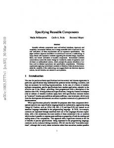
systems. Concerning the domain of run-time platforms, e.g., such criteria might relate to functional aspects such as the scheduling strategy deployed, or can refer to non-functional aspects such as the timing behaviour of specific services. The possible alternatives in each dimension make up the so-called categories. Categories of the scheduling dimension, for instance, are the available disciplines like round robin, first-come-first-served, shortest-job-first and so on. In addition to what can also be described with faceted classification schemes [16,17,20], Design Spaces allow to express favorable and unfavorable combinations of design choices. To this end, correlations between categories or between categories and dimensions can be specified. Such correlations are weighted on a continuous scale from -1 (choices must not be combined) to +1 (categories have to be chosen in combination) – see figure 2. Correlations represent in a semi-formal way parts of an expert’s knowledge about the domain and about possible solutions. While a DS thus in some sense represents a taxonomy for the variable aspects of systems in that domain, a selection in the DS –called a Design Space profile– characterizes a concrete system along this taxonomy.
threads lifecycle static dynamic
quantity bounded yes no -1
preemption yes no
synchronization mechanisms locks semaphors monitors ... -0,8
Figure 2. illustrates an excerpt from a Design Space describing run-time platforms. The four dimensions are related to the lifecycle model for threads, the questions whether the number of threads is bounded and if preemption is supported, and the synchronization mechanisms offered.
The original Design Space concept points out two subspaces: a requirements and a structural subspace. The first addresses the externally observable behaviour of the system, while the second is related to the internal structure and to implementation issues. Correlations within the requirements subspace are used to express interdependencies between single requirements. For example, an appropriate correlation might reveal the incompatibility of virtual memory management and real-time scheduling. Similarly, correlations within the structural subspace help to assure the consistency of the system’s design. Even more important, correlations between the two subspaces can be used to code design rules bridging the gap between requirements and implementation. Certain timing constraints, for instance, could thereby be explicitly stated to demand a specific type of interrupt handling. In the course of deploying Design Spaces, we have made some extensions to the original concept [4]. Some of
Proc. of the IEEE Int’l Conf. on Requirements Engineering (ICRE2000), Schaumburg, Illinois, USA, June 19-23 2000
these extensions relate to simplifying the handling of large Design Spaces. For example, related dimensions can now be defined to form a group, hierarchies allow selections in one dimension to hide or to disclose other dimensions, and sequences can define a preferred order in wich selections in a Design Space should be made. Other extensions have been introduced to increase the expressiveness of Design Spaces. Among others, continuous dimensions capable of holding integer or floating point values now complement the previously discrete character of dimensions. This consequently implies the need for an extended notion of correlations, too. Correlations can now combine several categories in a boolean expression and, more importantly, can also include formulas to map one continuous dimension to another. We also dropped the notion of a requirements and a structural subspace in favor for a set of distinct but interrelated Design Spaces. An Application Design Space and a Requirements Design Space now both take the role of the requirements subspace, and the entirety of several Component Design Spaces takes the role of the structural subspace. This basically syntactical modification was done for the sake of a clear separation of concerns and of improved manageability of the Design Spaces. Design Spaces can, depending on what kind of artefact they describe, reach a considerable size. For example, we have used between 40 and 80 dimensions each to describe multimedia servers, home automation systems and runtime platforms in our case studies. To sensibly handle this amount of information, tool support is indispensable. We have therefore developed two prototype tools (cf. figure 3), one for the interactive development of a Design Space and its structured representation, the other for interactively creating Design Space profiles and for automatically evaluating correlations. Design Spaces are currently stored as relational databases to which both tools have access via an ODBC interface. Our first tool, the Designer, allows to interactively define a Design Space in terms of dimension and correlations, and allows to set up and modify appropriate correlations. The second tool, the so-called Configurator, allows to enter Design Space profiles and to evaluate correlations. For a given profile, the Configurator automatically checks the profile’s consistency, gives hints about selecting dependent categories, and also offers the possibility to automatically preselect dependent categories.
Figure 3. The Configurator (top window) in this example is used to customize the QNX operating system along our QNX Design Space. The Designer (background window) allows to define and modify Design Spaces.
4. Requirements Capturing In combination with appropriate tool support, the Design Space technique can be applied favorably throughout requirements elicitation, analysis and run-time platform design. The natural starting point for such an overall process is the gathering of relevant requirements the application under consideration poses upon the platform. The by far most often case in current practice is to initially let the application developer state any requirements concerning the envisioned run-time platform without major restrictions [7]. Requirements statement is typically the task of the application developer, resulting in an informal document phrasing those desired properties of the platform he can think of. Where strict adherence to these requirements is of special concern –e.g. in safety critical systems–, the requirements are moreover formalized using techniques such as SCR [9], Statecharts [8], SDL [10], or temporal logic [14]. However, such a procedure being adopted from a general from-scratch development process bears several disadvantages, especially from the reuse point of view. One important drawback is the fact that the requirements stated by the application developer are (of course) not oriented at possible platform solutions. It is thus left up to the platform developer’s expertise and creativity to bridge the gap between requirements and implementation – which might end up in coding significant parts of the platform anew. Such an approach is ineligible if the development process is envisioned to be partially automated or at least to be strongly supported by tools. It is rather desirable to already direct the process of requirements elicitation towards possible solutions that take advantage of existing reusable assets. This means, the
Proc. of the IEEE Int’l Conf. on Requirements Engineering (ICRE2000), Schaumburg, Illinois, USA, June 19-23 2000
application developer has to be guided along some kind of questionnaire primarily only allowing to state those requirements that can be handled by existing platform components. Only in case the offered range of possibilities is absolutely unacceptable, new component variants will have to be implemented, resulting in the questionnaire to be revised. Design Spaces are our technique of choice to semi-formally prepare such questionnaires and to allow for a tool-supported processing. Concerning the target domain of embedded controllers for home automation systems, we have set up an Application Design Space currently comprising about 50 dimensions and representing an important part of our domain model. Figure 4 shows a small excerpt from this space in textual form: ADS1: ADS2: ADS3: ADS4: ADS5: ADS6: ADS7: ADS8: ADS9:
evt time Is the application event- or time-triggered? no Does the application use several threads of control? yes Number x of initial threads at system start INT no Threads lifecycle: are threads created dynamically? yes yes no Is the number of threads bounded? yes no Do some threads have priority over others? yes no Do threads have to work in parallel? yes no Do threads share common data? a b c d Do threads show specific characteristics? (a)none, (b)short bursts, (c)long bursts, (d)interactive ...
It should be noted that Design Spaces will not take the place of other description techniques such as SCR, SDL, Statecharts etc., but will complement this set. The advantages of deploying Design Spaces already in this early phase of the overall process are obvious: they guide the application developer at stating requirements, preventing incomplete or inconsistent requirements, and also form a sensible starting point for mapping requirements to a selection of components and their configurations.
5. Mapping Requirements to Components The transformation of an application profile into a selection of suitable components of the run-time platform comprises four logical steps as shown in figure 5: Application Design Space
step Œ Requirements Design Space step •
Figure 4. gives a small excerpt from our Application Design Space for the domain of embedded control systems for home automation. Component Design Spaces
This Design Space is arranged in terms of the application domain, rather capturing properties of the envisioned application than explicitly asking requirements on the runtime platform. According to our experience, this approach facilitates the application developers’ task in a natural way since they can concentrate on describing how the application is going to behave and do not have to worry about platform specific questions. The typical communications problem between the application developer –in this situation being the user of the platform– and the platform developer is thereby avoided. The interactive development of an application characterization along this Design Space, i.e. the development of an application profile, is supported by our graphical DS tool called Configurator, which also validates the profile’s consistency. The Application Design Space is part of our domain model; it has been set up in a joint effort by both an application domain expert and an operating systems expert as a result of a domain analysis. Although the DS is prepared in terms of the application domain, it is already oriented at possible platform variants: it is arranged in a way that a given ADS profile can easily be mapped to explicit requirements on the platform. The DS is furthermore subject to a continuous evolution. As new components are developed or new generic parameters are introduced in response to requirements that cannot be stated with the existing DS, the DS will grow and integrate new aspects.
Pool of generic components
step Ž
Architectures SIMK RTK QNX
step • Component frameworks
Figure 5. shows the 4 process steps leading from application properties to the selection of appropriate reusable components.
Step 1: Creating a platform DS profile The process starts with the creation of a Design Space profile of the envisioned platform. To this end, a Requirements Design Space is provided, covering functional and non-functional aspects of the platform under construction. The Requirements DS is another product of the domain analysis and thus as well part of the domain model. The Requirements DS is the Application DS’ counterpart, describing platform requirements in terms of the operating
Proc. of the IEEE Int’l Conf. on Requirements Engineering (ICRE2000), Schaumburg, Illinois, USA, June 19-23 2000
systems’ vocabulary. It has been set up by operating systems experts and is as well oriented at what can be realized with the existing set of generic components. Figure 6a) shows a small excerpt from this space:
to be a sensible starting point. It captures the origin for further design decisions, thereby improving traceability throughout the requirements engineering phase. Step 2: Selecting a platform architecture
a) RDS1: RDS2: RDS3: RDS4: RDS5: RDS6: RDS7: RDS8: RDS9:
yes no Is multi-thread support required? yes no Is dynamic thread creation required? yes no Is dynamic thread termination required? INT Size y of thread queues asg evt Dispatching on assignment or on event? yes no Is preemptive scheduling required? yes no Are thread priorities required? yes no Are synchronization mechanisms required? a b c d Scheduling strategy to be deployed (a)round robin, (b)shortest job first, (c)rate monotonic ...
b) (ADS1=event) 0,7 (RDS5=event) (ADS2=yes) 1,0 (RDS1=yes) (ADS2=no) 1,0 (RDS1=no) (ADS4=yes) 1,0 (RDS2=yes) (ADS5=x) 0,9 (RDS5=x+4) (ADS6=yes) 0,9 (RDS7=yes) (ADS7=yes) 1,0 (RDS6=yes) (ADS7=no) 0,5 (RDS6=no) (ADS8=yes AND ADS7=yes) 0,9 (RDS9=yes) (ADS9=interactive AND ADS7=yes) 0,8 (RDS9=round robin) (ADS9=short bursts AND ADS7=no) 0,7 (RDS9=shortest job first) Figure 6. a) gives a small excerpt from the Requirements Design Space used to capture requirements on the runtime platform. Part b) gives some examples for correlations mapping Application DS profiles to Requirements DS profiles.
While the Application DS mainly captures properties of the application, the Requirements DS formulates these properties in terms of requirements on the run-time platform. Some questions asked in the Application DS can directly mapped to questions in the Requirements DS (e.g., ADS6 and RDS7), others need a more sophisticated transformation. Such a transformation of a given application profile into a platform profile in the Requirements DS is supported by correlations between the two spaces (cf. figure 6b). Correlations in this context take the role of translation rules stating which application properties result in which required properties of the run-time platform. As far as such translation rules are clearly known, this step is automated by our DS tool. However, such a mapping often also depends on subtle aspects not being covered by the Design Spaces. Manual resolution is thus typically required, possibly leading to the idea of skipping this first step. But even if the application developer can be expected to have enough operating systems knowledge to use the Requirements DS right away, the Application DS remains
In a second step, the DS profile is used to select a platform architecture. A platform architecture is an abstract representation for a set of platform variants that adhere to the same design rationales. Design rationales concern, e.g., the system’s structure, component interaction paradigms and protocols, possibly existent infrastructures etc. In such a way, an architecture captures important systemwide design decisions and defines a notion of component compatibility: components that have been built for the same architecture share the same assumptions about these system-wide design decisions and are –to a certain extent– compatible by construction. Architecture selection is thus an essential prerequisite for successfully finding components that will fit together forming an effective solution [6]. The question of what is to be called an architecture of its own and what are just variants of the same architecture is ultimately a question of the chosen level of abstraction. We are currently working with components from three different systems which define the three architectures we are taking into consideration: the commercially available realtime operating system QNX [18] and two real-time kernels developed in our group. The decision about an appropriate architecture of course often relies on human expertise and cannot be automated completely. However, correlations resulting from experience with earlier projects showing the applicability of the deployed architectures to specific problems can give important hints. The architecture that is most likely to support the required properties can thus be chosen based on correlations between the Requirements DS and a single dimension listing the available architectures. Step 3: Creating component profiles One of the primary roles of an architecture is to define the structure of the platform, i.e, a consistent framework of component types. The architecture defines which types of components there might exist in the system, how components of these types can be combined and how they interact. Building a concrete platform from this architecture thus involves finding the right components of the required types and configuring them correctly. As the reuse pool might comprise several component variants of a certain type, the platform requirements have to be mapped to requirements on components. To this end, there are socalled Component Design Spaces associated to each component type defined in the component framework. Each Component DS is devoted to the possible properties of all existing variants of the respective type of component – figure 7 shows a small excerpt from the Component DS for QNX process manager components:
Proc. of the IEEE Int’l Conf. on Requirements Engineering (ICRE2000), Schaumburg, Illinois, USA, June 19-23 2000
a) CDS1.1: CDS1.2: CDS1.3: CDS1.4: CDS1.5: CDS1.6: CDS1.7:
Highest priority hardware interrupt [0..7] Disallow nested interrupts Disallow kernel restarts Number of processes Number of timers Number of kernel semaphores Number of shared segments in system image
Requirements Design Space
INT yes
no
yes
no
Component frameworks
INT
a)
INT INT INT
b) Component Design Spaces
SIMK RTK
QNX
b) (RDS4=x) 0,9 (CDS1.4=x+2) (RDS5=assignment AND RDS4=x) 0,7 (CDS1.5=x+1) (RDS8=yes AND RDS4=x AND CDS1.7=y) 0,7 (CDS1.6=x+y+2) (RDS9=rate monotonic) 0,9 (CDS1.2=yes) Figure 7. a) gives an excerpt from the Component DS for QNX process manager components. Part b) gives some examples for correlations to the Requirements DS.
The third step now consists in mapping the platform profile stated in the Requirements DS to profiles in the component spaces. To this end, operating systems experts have specified correlations to map overall platform requirements component types and to specific component properties. It should be noted that these correlations actually serve two purposes: first to select which component types are necessary at all, and second, which properties of the needed components are required. So one type of correlation binds selections in the Requirements DS to component types (type a in figure 8), and another type of correlations binds selections in the Requirements DS to selections in the Component Design Spaces (type b in figure 8). In order to have our DS tool uniformly handling both types of correlations, we internally represent component types as DS dimensions, too. Step 4: Selecting components The component profiles are finally used to select appropriate components from the reuse pool. In our approach, this classical problem of finding the right components to reuse has been eased in several ways. Firstly, the search space has been narrowed to a single architecture: only those components explicitly stated to be compatible with the architecture chosen in step 2 have to be taken into consideration. Secondly, component selection is done along the lines of the different component types, further narrowing the search space to that of specific types. To this end, the component developers have classified each reusable component as being of one or possibly several type(s) and as belonging to one or several architecture(s). Thirdly, as a result of step 3, the required component properties for each component type are formalized in terms of a Design Space profile. By having complemented
Figure 8. shows correlations between the Requirements DS, component types and Component Design Spaces. Correlations of type a) are used to select necessary component types, correlations of type b) determine the required properties of components of the selected types.
the descriptions of the reusable components by a Design Space profile of their properties as well, component selection can be based on simple profile comparisons (cf. figure 9). As a prerequisite, the developers of reusable components use the same Component Design Spaces as deployed in step 3 to characterize the properties of their implementations. These properties can then easily be matched against the required properties. As far as appropriate components are available, this step is completely automated by our Design Space tool. In case there are requirements that cannot be met by existing components, either the requirements have to be revised, or new components or component parameters have to be implemented. Component Design Space for specific component type
required profile
profile comparison
provided profile Figure 9. illustrates how comparisons between Design Space profiles are used to select appropriate components from the reuse pool.
The compatibility of the selected components is assured a priori by the components’ developers. They have designed the components to fit into the respective archi-
Proc. of the IEEE Int’l Conf. on Requirements Engineering (ICRE2000), Schaumburg, Illinois, USA, June 19-23 2000
tecture and to correctly interact with other components from that architecture. The set of necessarily existing components, how they can be combined and how they interact is furthermore defined by the architecture. We have coded important aspects of this architectural information in the form of correlations between component types, thereby defining the structures that can be built. These correlations interconnect component types or bind component types to certain profiles in Component Design Spaces (figure 10). Component Design Space for specific component type
QNX
Component framework
Figure 10. shows correlations between component types within the component framework and between DS profiles and component types.
The four steps as described above can of course not be performed strictly sequentially. The process of mapping requirements to component selections is rather an iterative and still a quite interactive one. Whenever appropriate solutions do not exist or cannot clearly be decided about, human intervention is required. For example, dead ends may occur where suitable components are missing. In such cases, operating systems experts have to extend the component pool, or backtracking might reveal a slightly different solution that is still close enough to acceptably meet the requirements. In any case, the whole process is supported by one consistent technique giving important hints based on design rules coded in terms of DS correlations.
6. Component Configuration and System Generation Up to this point, parameter settings of generic components have not been considered yet. However, most of the generic parameters fit seamlessly into this development approach based on Design Spaces. Selection parameters – being the by far most frequent type of parameters– can be represented directly in the respective Component Design Space: they take the form of discrete dimensions with categories describing the possible values of the parameters. A component description along the Component DS thus leaves such dimensions unselected thereby expressing the variability of the generic component. While for mere component retrieval these dimensions are ignored, known requirements with respect to these properties can be used to determine the parameter settings of retrieved components. Generative parameters of type INTEGER or FLOAT
can as well be represented as dimensions allowing for an easy configuration based on Design Spaces. In such a way, step 4 as described in the previous section not only covers component retrieval, but also serves for configuring generic components. More complex parameters that cannot be described with the Design Space technique currently remain subject to manual configuration, although Design Spaces can give sensible assistance in some cases. For example, correlations can relate certain requirements to informal hints for choosing appropriate parameter settings, or to pre-built code templates in case of code parameters. Taking generic parameters into account also poses the question of interdependencies between these parameters. While steps 3 and 4 assure the components themselves to be architecturally compatible by selection, unfavorable settings of their generic parameters might still result in incompatibilities. As far as such parameters are reflected in the respective Component Design Spaces, appropriate correlations denote favorable and unfavorable combinations of parameter values. Compatibility checks can thereby be automated by our Design Space tool. Assuming all required components have been retrieved and configured, system completion is then mainly left up to generators. These generators take generic components and the component’s parameter settings as inputs and translate them into (conventional) implementations with the desired properties [1,15]. While exceptional requirements might demand for manual implementations of highly specialized components, most of the run-time platform is automatically synthesized from reused components.
7. Conclusions and Further Work The presented approach is based on a process specifically tailored for the reuse of generic components. The Design Space technique has been shown to guide system development through all major steps from requirements capturing to system generation. In such a way, specific development tasks can be partially automated and substantial tool support for important design decisions can be given. The quality of this support of course depends on the amount of information that is actually available in the respective Design Spaces. For this reason, our approach draws important advantages from choosing a domain that has a restricted and well understood set of possible requirements and variances in solutions. A sensibly sized Design Space can thus capture most of the relevant requirements on the system. Furthermore, especially the aspect of reusing generic components profits from such a narrowed set of implementation variants. The overall approach, however, should be applicable to any other domain that is restricted in variance likewise and that is similarly well understood.
Proc. of the IEEE Int’l Conf. on Requirements Engineering (ICRE2000), Schaumburg, Illinois, USA, June 19-23 2000
Although complete automation of the development process is hard to achieve, the expressiveness of our Design Spaces can still be improved. For example, we are working on describing the available architectures in an Architecture Design Space. The rather pragmatic approach of having a single dimension for choosing an architecture could thereby be replaced by a more accurate description and more expressive correlations. Another point is the use of Design Space correlations for capturing component interdependencies – an aspect the Design Space technique might not be overly suited for. Here, more sophisticated composition rules could further improve the support that can be given during the development process. What also remains to be done is a quantitative assessment of our overall approach. Up to now, the presented concepts have been deployed separately in small case studies, performed in cooperation with a few students. One study has been conducted to compare tool-supported component retrieval with the effort for manually finding a suitable component, showing a clear reduction in search time. Another study has been conducted to show the general suitability of Design Spaces and especially to check the soundness of our correlations. In this study, the Application DS and the Component DS were used to guide a manual platform development process, yet without tool support. Results showed positive effects on the development time, the number of design errors and the traceability of decisions, and gave us important hints to fine-tune the correlations. In a third case study, several run-time platforms based on the QNX system have been built to match the requirements of a set of given applications. For each platform, both the typical manual configuration procedure and a semi-automatic, DS-based and tool-supported configuration was applied, showing similarily positive results. However, to substantiate this impression, we are planning to conduct more controlled experiments.
8. References [1]
Bass, L.; Clements, P.; Kazman, R.: Software Architecture in Practice, Addison-Wesley, 1997
[2]
Baum, L.: Towards Generating Customized Run-time Platforms from Generic Components, Proc. of the 11th Conference on Advanced Information Systems Engineering (CAISE’99), 6th DC, Heidelberg, Germany, June 1999
[3]
Baum, L.; Becker, M.; Geyer, L.; Molter, G.; Sturm, P.: Driving the Composition of Run-time Platforms by Architectural Knowledge, Proc. of the 8th ACM SIGOPS European Workshop, Portugal, September 1998
[4]
Baum, L.; Geyer, L.; Molter, G.; Rothkugel, S.; Sturm, P.: Architecture-centric Software Development Based on Extended Design Spaces, Proc. of the 2nd ARES Workshop (Esprit 20477), Las Palmas de Gran Canaria, February 1998
[5]
Biggerstaff, T.: The Library Scaling Problem and the Limits of Concrete Component Reuse, Proc. of IEEE Int’l Conference on Software Reuse, November 1994
[6]
Garlan, D.; Allen, R.; Ockerbloom, J.: Architectural Mismatch: Why Reuse is So Hard, IEEE Software, 12(6), 1995
[7]
Gotel, O. C. Z.; Finkelstein, A. C. W.: An Analysis of the Requirements Traceability Problem, Proc. of the 1st Int’l. Conf. on Requirements Engineering (ICRE’94), IEEE Computer Society Press, 1994
[8]
Harrel, D.: Statecharts: A Visual Formalism for Complex Systems, Science of Computer Programming No. 8, 1987
[9]
Heininger, K. L.: Specifying Software Requirements for Complex Systems: New Techniques and their Application, IEEE Transactions on Software Engineering, SE-6(1), January 1980
[10] ITUT-T: CCITT Specification and Description Language (SDL), Z.100, 1994 [11] Jacobson, I.; Griss, M.; Jonsson P.: Software Reuse - Architecture, Process and Organization for Business Success, ACM Press/Addison-Wesley, 1997 [12] Lane, T. G.: Guidance for User-Interface Architectures, in: Garlan. D., Shaw, M.: Software Architecture – Perspectives on an Emerging Discipline, Prentice Hall, 1996 [13] Lane, T. G.: Studying Software Architecture Through Design Spaces and Rules, Technical Report CMU/SEI-90TR-18, Carnegie Mellon Univ., 1990 [14] Manna, Z.; Pnueli, A.: The Temporal Logic of Reactive and Concurrent Systems: Specification, Springer, 1992 [15] Nehmer, J.; Sturm, P.; Baentsch, M.; Baum, L.; Molter, G.; Rothkugel, S.: Customization of System Software for Large-scale Embedded Applications, Computer Communications Vol. 20, Elsevier, June 1997 [16] Ossher, H.; Tarr, P.: Multi-Dimensional Separation of Concerns using Hyperspaces, IBM Research Report 21452, April 1999 [17] Prieto-Diaz, R.: Classifying Software for Reusability, IEEE Software, January 1987 [18] QNX Software Systems Ltd.: QNX System Architecture, System Documentation, QNX Software Systems, Canada, 1993 [19] Sametinger, Johannes: Software Engineering with Reusable Components, Springer, 1997 [20] Tarr, P.; Ossher, H.; Harrison, W.; Sutton, S. M.: N Degrees of Separation: Multi-Dimensional Separation of Concerns, Proc. of the Int’l Conference on Software Engineering (ICSE’99), May 1999
Proc. of the IEEE Int’l Conf. on Requirements Engineering (ICRE2000), Schaumburg, Illinois, USA, June 19-23 2000