landmarks, the challenge consists of a Simultaneous Localization and Mapping (SLAM) concept using laser data of all swarm members. 1 INTRODUCTION.
International Archives of the Photogrammetry, Remote Sensing and Spatial Information Sciences, Volume XL-1/W2, 2013 UAV-g2013, 4 – 6 September 2013, Rostock, Germany
MARTIAN SWARM EXPLORATION AND MAPPING USING LASER SLAM S. Nowaka,∗ , T. Kr¨ugera , J. Matthaeia , and U. Bestmanna a
Institute of Flight Guidance, Technische Universit¨at Braunschweig, Germany (stefan.nowak, th.krueger, j.matthaei, u.bestmann)@tu-braunschweig.de
KEY WORDS: Extra-terrestrial, Aerial, Robotic, SLAM, Tracking, Fusion, Navigation ABSTRACT: In order to explore planet Mars in detail and search for extra-terrestrial life the observation from orbit is not sufficient. To realize complex exploration tasks the use of automatic operating robots with a robust fault-tolerant method of navigation, independent of any infrastructure is a possibility. This work includes a concept of rotary-wing Unmanned Aerial Vehicles (UAVs) and Unmanned Ground Vehicles (UGVs) for Martian exploration in a swarm. Besides the scenario of Martian surrounding, with a small number of distinctive landmarks, the challenge consists of a Simultaneous Localization and Mapping (SLAM) concept using laser data of all swarm members. 1
INTRODUCTION
2
Previous explorations with manual controlled rovers have been successful in accessible areas. But rough terrains like mountains, canyons, and caves require an investigation with a manned crew, whose realization is expensive, dangerous and not yet possible from the technologies perspective. Alternatively automatic operating robots with a robust fault-tolerant method of navigation and independent of any infrastructure can be utilized. In this case the realization takes place with a swarm of cooperative acting unmanned rovers, like in Figure 1.
ENVIRONMENT
During the entire development the physical and environmental properties of Mars have to be considered. The planet rotates with ωMars = 14.62 °s , which is slightly slower than the rotational speed of Earth. On the surface the gravity is approximately g0,Mars = 3.71 sm2 , which is about a third as on Earth, but in the same scale (Arvidson (2013)). Therefore the primary navigation system, the Inertial Navigation System (INS), has to be adjusted on the basis of these parameters. The atmospheric pressure varies between 400 and 870 Pa at mean Mars radius, depending on the season [Williams (2010)]. This is 115 to 250 times smaller than at mean sea level (MSL) on Earth and equals the pressure at an terrestrial altitude of about 35 km. According to the atmospheric model of (Benson (2010)) the barometric pressure on Mars can be calculated by Equation 1 for altitudes up to 7000 m. p(h) = 699 · e−0.00009·h Pa
(1)
Pa The vertical pressure gradient at h = 0 m is dp dh = −0.06 m . In relation to the overall atmospheric pressure, this is a 0.09 ‰ decrement for a 1 m step upwards. On earth, this value is about 0.12 ‰ at mean sea level (MSL). As these values are also at comparable sizes, it has to be considered whether pressure sensors with a full scale range of about 10 hPa instead of 1100 hPa, like on Earth, would have a comparable performance.
Figure 1: Possible rover formation for Martian swarm exploration One key question is if UAVs will be able to fly in the atmosphere of Mars, and which technical innovations will be needed in order to do so. However, in this work rather the problem of a robust navigation will be the focus. Due to the required time for transmission of radio signals between Mars and Earth, remote controlled interactions with a rover have a dead time between 6 and 60 minutes depending on planetary constellation. Thus the direct and manual control is only possible for slow-moving ground vehicles and therefore especially flying vehicles must have automatic routines for a safe operation. In general a rover requires information about its states, surrounding terrain and the position relative to other swarm participants. Hence, the implementation of a robust navigation method includes complementary selfpositioning and relative positioning systems. In this context the idea of a comprehensive SLAM concept arised.
In contrast to Earth, Mars has almost no global magnetic field, only weak local magnetic fields in order of tenth of nT [Connerney et al. (2005)]. This makes magnetometer based navigation not usable for the application on Mars. 3
HARDWARE DESIGN
In the following, an overview of the hardware concept for the rovers is given and the used sensor acquisition system is introduced in detail. 3.1
UGV and UAV Overview
The basis chassis of the UGV is a four wheel rover, called DrRobot Jaguar 4x4, with a weight of 20.5 kg and a maximum additional payload of 30 kg. Each wheel is driven by its own motor, so that a skid steering is possible. The interior equipment was
This contribution has been peer-reviewed.
299
International Archives of the Photogrammetry, Remote Sensing and Spatial Information Sciences, Volume XL-1/W2, 2013 UAV-g2013, 4 – 6 September 2013, Rostock, Germany
Figure 2: Simplified structure of UGV and UAV components
motor is used. Power and Ethernet signals are fed to the laser scanner through slip rings, which allows continuous rotation. A microcontroller circuit reads out the turret angle with a resolution of 0.1 ° from the rotary encoder and governs the DC motor via PWM to achieve a constant rotational speed between 1 and 40 seconds per revolution. The microcontroller is able to synchronize its time base to an external PPS signal. Thus, it can timestamp a scan synchronization pulse from the laser scanner with the according turret angle in the scale of microseconds for IMU data fusion. See (Franzen (2013)) for construction and operation of this turret.
supplemented and replaced for the most part. Among others with two specifically developed boards, a Sensor Readout Unit and a Remote Control Unit. The UAV consists of a AscTec Pelican Quadrocopter with an actual take-off weight of 1.9 kg. The Sensor Readout Unit is the same self-developed board as in the UGV. The simplified structure of UGV and UAV is pictured in Figure 2. Both vehicles are equipped with a variety of sensors like different laser scanners, Inertial Measurement Units (IMUs), cameras and pressure sensors. 3.2
Sensor Readout Unit
The Sensor Readout Unit consists of a STM32F4 microcontroller and serves as a carrier for the IMU. This controller organizes the time synchronization of the system. The timer of the microcontroller generates a timestamp for incoming signals from the IMU and the laser scanners and is able to trigger cameras, the Main PC and other sensors. There is also the possibility to synchronize the timer with a Pulse Per Second-signal (PPS) of GPS-messages for test scenarios on Earth. Besides this board handles the readout of the IMU and executes the data transfer via SPI to the Main PC Unit. 3.3
no. 1 2 3 4 5
device bearing slip rings rotary encoder laser scanner geared motor
Figure 3: Technical description of the rotating laser scanner turret of the UGV
Main PC Unit
The UGV is equipped with a Main PC Unit based on a PC/104Express single board computer. The Main PC Unit of the UAV is an AscTec Mastermind CPU board with a Dual Core Intel Atom processor. The Main PC Unit collects and records the time-stamped data of all connected components and calculates control output values. The Remote Control Unit transposes these values and controls the motors of the wheels of the UGV. One essential sensor for environmental sensing for the UGV and the UAV is a laser scanner, which is described below.
4
SOFTWARE ARCHITECTURE
The software architecture is split in two sections. The first one handles the communication framework of the sensors including the different interfaces. The second section is about the structure of the sensor data fusion and the navigation algorithms. 4.1
Communication Framework
For the communication framework of the different software components, a modular design which is based on TCP/IP sockets was chosen. TCP/IP implementations are available for almost every The Hukoyu UTM-30LX(EW) is a single-layer laser scanner. These modern operating system, are independent of the hardware architecture and can also be used in Matlab/Simulink (Sysel (2009)). kind of sensors have become very small and light-weighted and Every rover delivers data via a TCP/IP socket for each sensor. therefore usable for small UAVs. The sensor has a maximum Several programs can run on the rover itself or on any other comrange of 30 m at an angular resolution of 0.25 ° over a detection puter connected by a wired or wireless LAN. Therefore a program angle of 270 ° and an update rate of 40 Hz. Therefore an adequate running on a desktop PC can access data as if it were on a rover detection of the environment is possible, but due to the singleand a comfortable developing process is being achieved. Data layer measurement only in one plane, i.e. in two dimensions. visualization as well as a sensor simulation can be done on exter3.4.1 Rotating Laser Scanner Turret For scanning the surnal computers serving the data via TCP/IP link. The data can be rounding environment in three dimensions, the laser scanner of recorded and replayed for testing different algorithms at the same the UGV is mounted on a specifically developed rotating turret, time and to get comparable results based on the same data. The same method can also be used for intra-swarm communication as shown in Figure 3. The construction is similar as in (Michalicek (2010)). Instead of a stepper motor, a simple geared DC and thus to simulate other swarm participants. 3.4
Laser Scanner
This contribution has been peer-reviewed.
300
International Archives of the Photogrammetry, Remote Sensing and Spatial Information Sciences, Volume XL-1/W2, 2013 UAV-g2013, 4 – 6 September 2013, Rostock, Germany
4.2
Navigation System
The essential navigation system for all rovers is the INS. It consists of a Micro-Electro-Mechanical Systems (MEMS) based IMU, ~e and accelerations ~e providing high dynamic body-fixed rates ω a which are used for stabilization and navigation. In this case the IMU ADIS16488 or optional the ADIS16375 from Analog Devices can be installed on the Sensor Readout Unit. Due to accumulation of sensor errors like colored noise and temperature dependent rift, this system has to be combined with supporting navigation data. Since there is no absolute navigation system like a Global Navigation Satellite System (GNSS) available on Mars, the rovers must use the surrounding terrain and nearby swarm members for navigation instead.
Figure 5: Vertical construction of the laser scanner of the UAV The mathematical description starts with the transformation of laser scanner measurement data, which is delivered in polar coordinates, to the cartesian coordinate system of the scanner (index l). This is being done using the angle θr of the laser ray and the distance of reflection dr : 0 ~ l = dr · cos(θr ) X (2) dr · sin(θr )
Optical Subsystems Laser Scanner Stereo/Mono Vision Startracker Radio based Relative Positioning Ultra-Sonic Range Finder Air Data other sensors Multi-Sensor Data Fusion ˆ ~φˆ ) Fusion Filter (~r,ˆ ~v,
INS ~e ) IMU (~e a, ω
generated. Position translation and attitude changes between each single scan are measured by the IMU. These information and the laser measurements are merged in order to achieve a correct reconstruction.
The coordinates of the laser scanner Xl are shifted to the body~s . fixed system of the UAV (index g), using the position offset X The transformation of the body-fixed coordinate system to the ~n appears in the following: navigation frame X ~l + X ~s ) ~n = X ~0 + Mgb · (X X
corrections Figure 4: Multi-sensor data fusion of INS and the supporting subsystems An Extended Kalman Filter (EKF) is utilized to realize a loosely coupled sensor data fusion of all navigation subsystems an. Besides, corrections for the INS and some subsystems are calculated by the filter, see Figure 4. The data output includes the estimated ˆ ~φˆ of the vehicle. Due to the position, velocity and attitude ~r,ˆ ~v, loosely coupled fusion, state-dependent calculations of the supporting subsystems require certain states of the rover. 5
SLAM CONCEPT
Using a single-layer laser scanner and established Simultaneous Localization And Mapping (SLAM) algorithms, a good relative positioning to nearby objects is possible. This combination is most often being utilized in urban areas or indoor scenarios. In these cases the arrangement of detectable objects is advantageous to be used for SLAM. A single-layer laser scanner which is mounted horizontally can be used to support navigation if it can detect enough objects in the sensor plane. Generally in natural surroundings, especially on Mars, in the horizontal plane not enough obstacles can be detected. So two solutions for the different robots are proposed. A vertical mounted laser scanner for the UAV and the rotating laser scanner for the UGV. 5.1
UAV Vertical Laser Scanner Concept
(3)
~0 describes the translative position of the UAV The parameter X and the matrix Mgb the rotation from the body-fixed to the geodetic frame: " c(Θ)c(Ψ) Mgb = c(Θ)s(Ψ) −s(Θ)
s(Φ)s(Θ)c(Ψ) − c(Φ)s(Ψ) s(Φ)s(Θ)s(Ψ) + c(Φ)s(Ψ) s(Φ)c(Θ)
Where c stands for cos and s for sin. 5.2
# c(Φ)c(Θ)c(Ψ) + s(Φ)s(Ψ) c(Φ)s(Θ)s(Ψ) − s(Φ)c(Ψ) c(Φ)c(Θ) (4)
UGV Laser Turret Concept
Because of the Martian surroundings the laser scanner of the ground vehicle needs a motion of the scanner plane to provide useful environmental data. In (Holz et al. (2008)) for instance the laser scanner is attached to a rotatable horizontal axis. In the presented work a rotation of the scanning layer is realized by a rotating turret, shown in Figure 6, which is described in 3.4.1. As a consequence a three-dimensional measurement capability is made possible.
Figure 6: Laser turret of UGV
In case of the flying rover, the laser scanner is mounted in vertical direction, see Figure 5. This orientation of the scanner enables a three-dimensional surface modeling with a 2D laser scanner like in (Thrun et al. (2003) and (Wu et al. (2013)). By combining movement and yawing of the UAV different scan-patterns can be
The mathematical description of the first transformation is more complex in this case. The rotation of the scanner implies a second angle φs , so that the measurement data consist of spherical
This contribution has been peer-reviewed.
301
International Archives of the Photogrammetry, Remote Sensing and Spatial Information Sciences, Volume XL-1/W2, 2013 UAV-g2013, 4 – 6 September 2013, Rostock, Germany
coordinates. The calculation to a turret-fixed coordinate system ~ t is below: X dr · cos(φs ) · sin(θl ) ~ t = dr · sin(φs ) · cos(θl ) X (5) dr · cos(θl ) Like the transformation for the UAV, this cartesian coordinate system is shifted to the body-fixed coordinate system of the UGV. ~ t of the turret is inserted. Finally the Therefore a position offset X transformation of the body-fixed system to the navigation frame is similar to the UAV transformation: ~g = X ~0 + Mgb · (X ~s + X ~t ) X
(6)
The body-fixed coordination system of the UGV equals the one of the UAV and not the common one for ground vehicles. Therefore the transformation matrix Mgb stays the same. 5.3
maps generated from data collected by Mars orbiters can be used via the virtual planet builder. Additionally CAD models from the UGVs as well as the UAVs are implemented for visualization. The simulation is programmed in C++, based on the open source library OpenSceneGraph1 . As the UGV attitude depends on the surface below it is calculated processing the collision between all four wheels and the surface. The simulator then positions the rover on the surface and returns the simulated scan data from the resulting pose. Starting with the first beam, a collision detection with the surface will be done in direction of the beam. If there is a collision within the range of the simulated scanner, this range will be used as simulated measurement. The next beam direction is calculated and a new collision detection done. Thus, repeatable laser range data is obtained. Afterwards a laser scanner sensor error model can be added to this simulated data. In the same manner, the laser scanner mounted on the flying UAV will be implemented.
Swarm Mapping and Localization Concept
Different versions of SLAM-algorithms are common and state of the art in the field of robotics. Also the idea of combining two or more data sources to one three-dimensional map is already mentioned among others in (Carle and Barfoot (2010)). The work of (Carle and Barfoot (2010)) includes a method of matching a orbital a priori map and rover based scans. The goal consists of long-range rover localization for distances of 10 km and more. Other projects, like (Thrun et al. (2003)) and (Wu et al. (2013)) are using an UAV with a vertical mounted laser scanner to generate a terrain model, but the positioning concepts are utilizing GPS, which is not available on Mars. The presented work considers a SLAM concept with three components of data sources. A priori surface information of Mars from previous orbiters, the three-dimensional scans of the ground vehicles and the vertical scans of the UAV. First, all members of the swarm collect IMU and laser scanner data individually. The moving vehicles scan new terrain ahead, while the overlapped scanned area behind the vehicles can be used for localization and correcting IMU data. Further, rough a priori surface information in scales of meters are already available from Mars orbiters. This can be used to establish an absolute localization by matching distinctive landmarks and estimate various drift parameters. In the same turn, the surface model will be refined by the mapping process. Furthermore, the swarm participants share the gathered data via a data link and therefore the achieved map can be consolidated from different perspectives. The exploration and mapping of the unknown Martian surface require a volumetric representation of the recorded space. For this task several methods and libraries are already available. A decision to use OctoMap was made, because it allows for an effective data processing (Hornung et al. (2013)). The mapping concept of OctoMap uses a probabilistic occupancy estimation and is based upon octrees. These octrees are a hierarchical data structure and each node of it stands for a cubic volume. Every cube can be recursively subdivided into eight sub-cubes. This has the advantage that different resolutions of the same map can be chosen. Therefore OctoMap models the data continuous and minimizes the storage requirement. 6
Figure 7: Visualization of OSG-simulation The simulator can be interfaced via a TCP/IP socket and therefore can communicate with a Matlab/Simulink simulation as well as the real rovers and laser scanners. A first implementation showed that the simulated scan data can be achieved in real time for multiple rovers at the same time. 7
RESULTS
In order to estimate the capabilities of this concept, first test flights have been done an a local model plane airfield. Especially the ability to merge the laser scanner measurements from the UAV and the UGV has been of interest during the tests.
SIMULATION
For designing and testing algorithms it is practical to use a simulation environment which includes all relevant components. Therefore the environment of Mars is reconstructed so that a simulation of laser scanner measurements is possible. Various elevation
Figure 8: Picture of UAV in front of the test object 1 www.openscenegraph.org
This contribution has been peer-reviewed.
302
International Archives of the Photogrammetry, Remote Sensing and Spatial Information Sciences, Volume XL-1/W2, 2013 UAV-g2013, 4 – 6 September 2013, Rostock, Germany
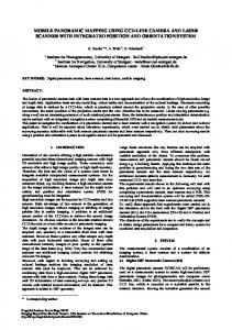
(a) Picture of scanned object
(b) Point cloud of UAV and UGV
(c) Visualization with OctoMap
Figure 9: Scanned object A VW bus was choosen, because it allows for a seperate measurement from the top and from the side. It also has plane surfaces in order to estimate the quality of the measurements. In Figure 8 the UAV is shown in front of the car. The quadrocopter was flying straight over the white vehicle at an altitude of approx. 5 m, while the UGV was scanning from a fixed position beside the bus. In Figure 9b the results of the two scans of UAV and UGV are combined. The red point cloud results from the UGV laser scanner measurements from the ground and the blue point cloud displays the measurements from the UAV. The point clouds of the two sources complement one another and deliver a good reconstruction of the scanned car. The third Figure 9c shows the combined point cloud, visualized with the OctoMap. The contour of the car is well defined, despite the illustration with larger cubes. The alignment of the point clouds of the two sources in overlapping areas has to be quantified in the future. With this information also an estimation of the quality of the matching can be performed, which will be used for the navigation filter. 8
CONCLUSION AND OUTLOOK
The target of this project is the theoretical exploration of unknown areas on Mars by the use of a robotic swarm. This paper describes a concept of environmental mapping with laser scanners of several rovers. The combination of ground vehicles and aerial vehicles offers different perspectives to scan the environment. The results of the first test flights are showing the completion of the sensor data by two points of view. This idea creates a good base for detailed environmental maps. Additionally a priori surface information offer an ability to correct maps, generated by SLAM algorithms and enhance location accuracy. Due to a priori maps, detailed laser scans of two perspects, the use of SLAM algorithms and a precise time-stamping of IMU it might be possible to develop a stable navigation solution in unknown environment. 9
ACKNOWLEDGEMENTS
This work has been performed within the Valles Marineris Explorer (VaMEx) project, which is partly funded by the Federal Ministry of Economics and Technology administered by DLR Space Agency (FKZ 50NA1212) and the Bavarian Ministry of Economic Affairs, Infrastructure, Transport and Technology administered by IABG GmbH (ZB 20-8-3410.2-12-2012). 10
Benson, T., 2010. Mars Atmosphere Model. NASA. http://www.grc.nasa.gov/WWW/k-12/airplane/ atmosmrm.html 17.05.2013. Carle, P. and Barfoot, T., 2010. Global Rover Localization by Matching Lidar and Orbital 3D Maps. Connerney, J. E. P., Acuna, M. H., Ness, N. F., Kletetschka, G., Mitchell, D. L., Lin, R. P. and Reme, H., 2005. Tectonic Implications of Mars Crustal Magnetism. In: Proceedings of the National Academy of Sciences, Vol. 102, ISs. 42, pp. 14970– 14975. Franzen, F., 2013. Vorrichtung zur 3d-Umfeldwahrnehmung mit einem Laserscanner auf einem unbemannten Fahrzeug. Bachelor Thesis, Technische Universit¨at Braunschweig, Institute of Flight Guidance. Holz, D., L¨orken, C. and Surmann, H., 2008. Continuous 3D Sensing for Navigation and SLAM in Cluttered and Dynamic Environments. Proceedings of the 11th International Conference on Information Fusion. Hornung, A., Wurm, K. M., Bennewitz, M., Stachniss, C. and Burgard, W., 2013. OctoMap: an efficient probabilistic 3D mapping framework based on octrees. Autonomous Robots 34(3), pp. 189–206. Michalicek, G., 2010. Development of a 3D SLAM Exploration System. PhD thesis, Universit¨at Hamburg, Hamburg. Sysel, M., 2009. TCP/IP Output from the Simulink. In: M. Fikar and M. Kvasnica (eds), Proceedings of the 17th International Conference on Process Control ’09, Slovak University of Technology in Bratislava, trbsk Pleso, Slovakia. Thrun, S., Diel, M. and Haehnel, D., 2003. Scan Alignment and 3-D Surface Modeling with a Helicopter Platform. International Conference on Field and Service Robotics. Williams, D. R., 2010. Mars Fact Sheet. NASA. http://nssdc. gsfc.nasa.gov/planetary/factsheet/marsfact.html 17.05.2013. Wu, J., Li, Q., He, M. and Zhang, F., 2013. A Terrain Model Generation Method Based on 2D Plan Laser Scanner for Micro UAV Autonomous Flight. In: Proceedings of the 2012 International Conference on Information Technology and Software Engineering, Vol. 211, Springer Berlin Heidelberg, pp. 215– 225.
REFERENCES
Arvidson, R. E., 2013. Mars Gravity Models. NASA. http: //geo.pds.nasa.gov/dataserv/gravity_models.htm 17.05.2013.
This contribution has been peer-reviewed.
303