Mask Assignment and Synthesis of DSA-MP Hybrid Lithography for sub-7nm Contacts/Vias Yasmine Badr
Andres Torres
Puneet Gupta
Electrical Engineering Department University of California, Los Angeles
Design To Silicon Division, Mentor Graphics Corporation
Electrical Engineering Department University of California, Los Angeles
[email protected]
[email protected]
[email protected]
ABSTRACT Integrating Directed Self Assembly (DSA) and Multiple Patterning (MP) is an attractive option for printing contact and via layers for sub-7nm process nodes. In the DSA-MP hybrid process, an optimized decomposition algorithm is required to perform the MP mask assignment while considering the DSA advantages and limitations. In this paper, we present an optimal Integer Linear Programming (ILP) formulation for the simultaneous DSA grouping and MP decomposition problem for contacts and vias. Then we propose a heuristic and develop an efficient algorithm for solving the same problem. In comparison to the optimal ILP results, the proposed algorithm is 197x faster and results in 16.3% more violations. The proposed algorithm produces 56% fewer violations than the sequential approaches which perform DSA grouping followed by MP decomposition and vice versa.
Keywords Directed Self Assembly, DSA, Multiple Patterning, MP, Decomposition, Moore’s Law, Technology
1.
INTRODUCTION
In continuous search for new technologies to enable the sub-7nm nodes, Directed Self Assembly(DSA) has presented itself as a strong candidate, especially with the continuous delay of Extreme Ultraviolet Lithography (EUVL). Even with EUVL in production, there are far more challenges with the transition to high-NA EUVL which will be needed for sub-11nm resolution, making the partnership of EUVL with Multiple Patterning (MP) an alternative option [10]. Thus, whether EUVL comes into play or not, Multiple Patterning is expected to enable several sub-7nm nodes. With the cost being the main drawback of MP and with DSA having native frequency multiplication properties, substituting one mask in an MP process with DSA is a tempting cost reduction[12]. In addition, DSA has been reported to possess Permission to make digital or hard copies of all or part of this work for personal or classroom use is granted without fee provided that copies are not made or distributed for profit or commercial advantage and that copies bear this notice and the full citation on the first page. Copyrights for components of this work owned by others than ACM must be honored. Abstracting with credit is permitted. To copy otherwise, or republish, to post on servers or to redistribute to lists, requires prior specific permission and/or a fee. Request permissions from
[email protected]. DAC ’15 June 07 - 11, 2015, San Francisco, CA, USA Copyright is held by the owner/author(s). Publication rights licensed to ACM. ACM 978-1-4503-3520-1/15/06 ...$15.00. http://dx.doi.org/10.1145/2744769.2744868.
Figure 1: An example directed self- assembly process of a diblock co-polymer using Graphoepitaxy
significant rectification capability in CDU and Edge Roughness for contacts[14]. DSA has been successfully demonstrated for contact holes (for e.g., [5]) and lamellae (for e.g., [16]). Since DSA is capable of printing dense nano features of roughly uniform dimensions [13], it is a very good fit for contact and via layers and we focus on these layers here. In this work, we focus on the hybrid DSA-MP process for contact/via holes, and study the problem of MP decomposition and DSA grouping. DSA Grouping is the process of selecting which contacts need self assembly by the same guiding template, while MP decomposition is the problem of determining the mask for every polygon. Up to the authors’ information, this is the first work that handles the algorithmic problem of mask synthesis for the hybrid DSA-MP process Our contribution is summarized as follows: • An optimal Integer Linear Programming (ILP) formulation is presented to perform the mask assignment and DSA grouping simultaneously. • A heuristic algorithm is proposed to solve the same problem, efficiently. Then the proposed algorithm is benchmarked against our ILP formulation to assess the quality of the results. • Results of the proposed heuristic are compared to the results of the sequential approaches, discussed in [2], which apply MP decomposition followed by DSA grouping and vice versa.
1.1
Brief Introduction to DSA
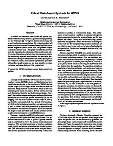
Self-Assembly is the phenomenon that occurs when block co-polymers composed of immiscible blocks phase-separate into organized structures [17]. For example, a diblock copolymer can self-assemble into periodic structures of one type of block into a matrix of the other. Lithographicallyprinted patterns (in the Graphoepitaxy scheme) or chemicallytreated surfaces (in the Chemoepitaxy scheme) are used to direct the self-assembly process. The graphoepitaxy process for contact holes is shown in Figure 1, where trenches are lithographically printed first, and then the surface is spincoated with the block co-polymer (BCP). Upon thermal an-
nealing, the phase separation occurs, and with a particular BCP and surface treatment of substrate [11], cylinders are obtained within the guiding pattern. Then one of the blocks is selectively etched, and the other block acts as a mask to transfer the pattern to the substrate [8]. Thus pitch multiplication of the lithographically-printed patterns can be achieved. The realizable assembled pitch depends on the block copolymer used.
1.2
DSA Capabilities
The block copolymer has a natural pitch L0 , to which it assembles, if not strongly guided by templates. To create a hole array with a pitch different from the natural pitch of the block copolymer, strong confinement is needed in the templates[18]. Smaller templates achieve stronger lateral confinement for the block copolymer leading to more precise control of the self assembly process[3, 5]. In addition, smaller defects density can be obtained with smaller size of templates [4, 9, 15]. Accordingly templates should be designed such that a very small number of contacts are created per template [12]. In addition, previous research has reported that using peanut-shaped templates with a very narrow neck between every pair of contacts can lead to less placement error[12]. However well-modulated peanut shapes are hard to print in 193i photolithography, therefore it is preferred to have the pitch of grouped contacts close to the natural pitch of the copolymer, not to have more than one single pitch value in one DSA group and to avoid 2D groups altogether [12]. Diagonal groups (which have larger pitch than L0 ) are also not desired because they need very strong confinement which can only achieved by very complicated peanut-shape guiding templates which are also hard to print in 193i photolithography.[6].
1.3
CAD Flow for DSA
In a process which employs Single Exposure only and DSA, the guiding templates need to be determined based on the given contact/via layer. Figure 2 shows a typical flow that is used to design the guiding templates. First, the DSA grouping algorithm determines which contacts are to be assembled using the same guiding template and hence the groups are generated. The grouping algorithm has to consider the lithography spacing constraints which the guiding templates will need to satisfy. For each group, a guiding template is synthesized. The synthesis process attempts to reverse-engineer the self assembly process in order to come up with the correct templates. The templates then undergo the classical optical treatment like OPC and SRAF insertion to enhance the resolution. Finally verification is performed, to compare the expected assembled contacts (based on the generated templates) to the target contacts. However in a technology that has multiple exposures, the DSA grouping method has to be coupled with the mask assignment method. In [2], it has been shown that cascading the traditional DSA grouping method with the Multiple Patterning Decomposer, which are both unaware of the hybrid nature of the process, produces poor results. In this paper we study the optimal and heuristic algorithms that can solve the DSA grouping and Mask assignment problem for the hybrid DSA-MP process. The rest of the paper is organized as follows: section 2 describes the hybrid DSA-MP process assumed in this work
Figure 2: CAD Flow for DSA in a Single Patterning Process
and explains its requirements. In section 3, we introduce the graph structure that we use in our algorithms. Section 4 presents an optimal Integer Linear Programming (ILP) formulation for the problem. In section 5, we present an efficient heuristic for solving the same problem. Finally, results are presented in section 6 and conclusions and future work are presented in section 7.
2.
HYBRID DSA-MP PROCESS
There are two alternative schemes for a hybrid DSA-MP process for contact/via holes[12]. In the first scheme, each of the N masks prints the guiding templates for DSA, so all holes will be created as a result of the self assembly of the block copolymer. In the second scheme, some of the masks will directly print the contact holes and thus do not apply DSA. In this work, we only focus on the first scheme, where each patterning step is followed by self assembly of block copolymer. We assume that 193i is used to print the guiding templates. Accordingly, DSA-grouped contacts are only allowed to be collinear and manhattanly-aligned, because the templates required to guide non-collinear and non-manhattan groups cannot be manufactured by 193i lithography reliably. The work in this paper is only concerned with contact/via hole patterning. Moreover, we assume the contact holes are all of same size. Thus, given a process which has Multiple Patterning (N masks) and DSA, it is required to do the DSA grouping and decompose the contacts onto the N masks; in order to minimize the number of mask violations. In a violation-free solution, any two contacts with an inter-distance less than minimum spacing rule are either assigned to different masks or in the same DSA group. Stitch-free decomposition has been assumed because most of the templates are expected to have small size. There are several important parameters in this problem: 1. Minimum Grouping distance(min dsa): minimum distance that can exist between two contacts in a DSA group. This distance is usually derived from the natural pitch (L0 ) of the block copolymer as follows: min dsa =L0 - contact width 2. Maximum grouping distance(max dsa): maximum distance that can exist between two neighboring contacts in one DSA group. This is derived from the properties of the block copolymer, because its self-assembly pitch can not be stretched beyond a certain threshold.
Figure 3: Ranges of distance between two polygons, where DSA and/or MP can resolve the spacing conflict. Figure 5: Simple example for a connected component on GG. Contacts a and c do not have direct grouping edge, but a grouping path exists between them. Yet, they must not be grouped.
(SG) when only the spacing edges are of interest. Sections 4 and 5 will show how the hybrid graph is used.
4.
Figure 4: Hybrid Graph between five contacts. Grouping edges are shown as solid lines, while spacing edges are shown as dotted curves. Every distance on this graph is assumed to be at least greater than min dsa. A spacing edge exists wherever the distance between two contacts is less than litho dist and a grouping edge exists wherever two direct-neighboring contacts can be grouped, i.e. they have an inter-distance that is the in the acceptable DSA grouping range, and are aligned on same X-axis or Y-axis. Notice that contacts a and d are not connected by a grouping edge although their inter-distance is within the grouping range but they do not satisfy the alignment constraint.
3. Minimum Lithography Distance(litho dist): minimum space that can occur on a single mask 4. Maximum DSA Group Size(max g): maximum number of contacts that can be grouped together 5. Number of masks(N ): number of exposures in the process. We use b to denote the minimum number of bits required to encode this number of masks: b = ceil[log2 (numberof M asks)] In Figure 3, the distance range between two contacts is divided into three regions, showing whether DSA grouping and/or assignment to different masks (MP) can be used to resolve the spacing violation. Outside the DSA-allowed range [min dsa, max dsa], only MP can be used to resolve the conflict between the two contacts. Note that it has been assumed that litho dist has larger value than max dsa which complies with the typical ranges in literature.
3.
HYBRID GROUPING /SPACING GRAPH REPRESENTATION
In this section, the new graph structure which considers both DSA and MP is explained. We use a hybrid grouping/spacing graph (GG/SG). Each contact is represented as a graph node. There are two types of edges: spacing edges, and grouping edges. A spacing edge exists between every two contacts that are within litho dist from each other. A grouping edge is created between every two direct-neighboring contacts that can be grouped into the same guiding template, i.e. that are aligned on the same horizontal or vertical axis, and the distance between them is within the DSA grouping interval: [min dsa, max dsa]. An example of the hybrid graph is shown in Figure 4. When we are only interested in the grouping edges, we refer to the graph as Grouping Graph (GG), and we refer to it as Spacing Graph
ILP FORMULATION
In this section, we present an optimal formulation for the simultaneous DSA grouping and MP decomposition problem, based on ILP. In a hybrid DSA-MP process, a conflict between two contacts means that they have an inter-distance less than the litho dist, but are assigned to the same mask and they do not lie in the same DSA group. In this formulation, the objective is to minimize the number of conflicts. The constraints are derived from DSA as well as lithography requirements. The constraints are generated based on the distance between every pair of contacts which have an inter-distance less than litho dist, according to the distance number line shown in Figure 3 which is summarized as follows: if the distance is less than min dsa or greater than max dsa, then the two contacts have to to be assigned to different masks. If the distance is greater than min dsa but less than max dsa then the pair of contacts are either to be assigned to different masks or grouped together for DSA. Otherwise, a conflict occurs. To represent the problem in linear constraints, binary variables are used to encode the mask number, like [19]. Our ILP works for Double Patterning (DP), Triple Patterning (TP), Quadruple Patterning (QP) and other higher powers of two. However for simplicity of the notation, we only present it for QP, and we show later the differences in the generated ILP when a different number of masks is used. For QP, two bits are required to represent the mask. To generate the ILP constraints, it is required to construct the hybrid graph and then find the connected components in the GG. If two contacts belong to the same connected component, then a path of grouping edges exists between them and therefore they can get grouped through that grouping path. However some of them may not be groupable because of DSA distance constraints or because they are not manhattanly aligned, and thus their grouping has to be explicitly prohibited via special constraints. For example, in Figure 5, contacts a and b are allowed to be in same group, and contacts b and c can also be in same group, but these two simultaneous groupings imply the grouping of a and c which is disallowed. Therefore constraints must be added to prohibit grouping of non-groupable pairs that lie in the same connected component like the case of contacts a and c in Figure 5. The variables and notation used are explained in Table 1. The mathematical formulation is as follows: minimize XX i
j
Cij
(1)
Table 1: Notation used in ILP Formulation kth bit of mask index of ith contact Flag indicating if ith and j th contacts are grouped Similarity variable indicating if kth bits in masks of ith and j th contacts are identical Flag indicating if ith and j th contacts are in conflict set of spacing edges in GG/SG set of grouping edges in GG/SG Flag indicating if ith and j th contacts belong to same connected component in GG Flag indicating if grouping of ith and j th contacts is forbidden because they are not aligned or their inter-distance is not DSA-compliant (region A or C in Figure 3)
Mik Gij Sijk Cij SEs GEs Conn(i, j) F G(i, j)
subject to : Figure 6: The proposed DSA Grouping - MP Decomposition flow
Sij1 + Sij2 + (1 − Gij ) ≤ Cij + 1
∀ (i, j) ∈ SEs
(2)
Sij1 ≥ 1 − Mi1 − Mj1 Sij1 ≤ 1 − Mi1 + Mj1
∀ (i, j) ∈ SEs ∀ (i, j) ∈ SEs
(3a) (3b)
Sij1 ≤ 1 + Mi1 − Mj1 Sij1 ≥ −1 + Mi1 + Mj1
∀ (i, j) ∈ SEs ∀ (i, j) ∈ SEs
(3c) (3d)
Sij2 ≥ 1 − Mi2 − Mj2 Sij2 ≤ 1 − Mi2 + Mj2
∀ (i, j) ∈ SEs ∀ (i, j) ∈ SEs
(3e) (3f)
Sij2 ≤ 1 + Mi2 − Mj2
∀ (i, j) ∈ SEs
(3g)
Sij2 ≥ −1 + Mi2 + Mj2
∀ (i, j) ∈ SEs
(3h)
Sij1 ≥ Gij
∀ (i, j) ∈ GEs
(4a)
Sij2 ≥ Gij
∀ (i, j) ∈ GEs
(4b)
Gij = 0
∀ F G(i, j) = 1
(5)
Gia + Gja ≤ 1 + Gij ∀ Conn(i, j) =1, Conn(i, a) = 1, Conn(j, a) = 1 X
Gij ≤ max g − 1
∀i
(6) (7)
j,Conn(i,j)=1,i6=j
The objective function in equation 1 aims at minimizing the number of conflicts. Each of the constraints in Equation 2 is used to set the conflict variable between two contacts having a spacing graph edge, if they are assigned to the same mask and are not DSAgrouped. Constraints in Equations 3a-3h are linear representation of the XNOR boolean relationship between two mask bits (e.g. Sij1 =Mi1 XNOR Mj1 ) to set the similarity variable if the corresponding mask bits are identical. The constraints in Equations 4a and 4b ensure that any grouping variable between two contacts can only be asserted if the two contacts are assigned to the same mask. Constraints in Equation 5 disallow grouping of pairs of contacts that do not satisfy DSA constraints. In addition constraints in Equation 6 impose the semantics of transitive grouping, i.e. if contacts x and a are grouped and contacts y and a are also grouped, then contacts x and y are grouped as a result. Finally constraints in Equation 7 enforce the maximum group size, since smaller group sizes have been found to lead to more robust assembly [3, 5, 12] due to better lateral confinement. In case of Triple Patterning, one more constraint is required per polygon to prohibit using the unused mask combination [19].
Note that for ease of understanding, the presented formulation hides some details which have been implemented to save memory. For example, the grouping variables are only created for pairs of contacts which belong to the same connected component.
5.
PROPOSED ALGORITHM
Since the optimal ILP does not scale to dense full-chip designs, we present a heuristic algorithm to solve the decomposition and grouping problem efficiently. The objective is to try to resolve as many conflicts as possible by grouping or assignment to different masks. To achieve this objective, we use the heuristic of maximizing the chance of grouping in the whole contact layer, which is expected in return (and confirmed by experiments) to maximize the possibility of being able to fix conflicts by DSA grouping. In other words, our objective is to find the biggest number of noncontradicting groupable pairs of contacts. On the grouping graph, this problem translates to finding the maximum number of grouping edges with no common nodes (i.e. contacts), since every grouping edge represents a grouping opportunity for the involved pair of contacts. This formulation is exactly the Maximal Cardinality Matching(MCM), which finds the maximum number of disjoint edges and which can be solved in polynomial time using Edmond’s algorithm [7]. We used an O(mn alpha(m,n)) implementation of the algorithm, where m is the number of edges, n is the number of vertices and alpha(m,n) is the inverse Ackerman function and is upper bounded by 4. The flow of the proposed algorithm is shown in Figure 6. At the beginning, the hybrid grouping/spacing graph structure described in section 3 is constructed. Then the maximum cardinality matching of the grouping graph is found and accordingly, the spacing edges between the matched vertices are then removed from the spacing graph 1 , and we have a modified spacing graph SG’. The idea is to drop the spacing edges between polygons which can be grouped. When the Multiple Patterning decomposer is then run on SG’, it does not have to assign these groupable contacts to different masks because they can be printed as one DSA group. Then, the matched pairs of contacts are processed; if they got assigned to the same mask, then a DSA group is created for them on their mask. Otherwise, each is left as a 1
Every grouping edge is also a spacing edge, because we assume max dsa is smaller than litho dist.
DSA group of a single contact. The algorithm up to this point can only produce groups of singletons and pairs at the largest. Last, we attempt to resolve the remaining coloring conflicts by merging the conflicting groups if they satisfy the DSA constraints, thus tentatively creating groups larger than two.
Example As an example, consider the hybrid graph shown in Figure 7a for a layout snippet. Assume the maximal cardinality matching solution has the two edges: b - e and c - d, as shown in Figure 7b. After removing these spacing edges, the modified spacing graph SG’ is obtained as shown in Figure 7c and after the graph coloring with 3 masks, we get the decomposed output shown in Figure 7d. Since the matched contacts b and e were assigned to the same mask, they form a DSA group together. The other contacts form three groups, of one contact each. The final grouping and decomposition result is shown in Figure 7e.
each separate mask GP MP: DSA grouping followed by MP decomposition Both MP GP and GP MP have been implemented by using the conventional Calibre Multiple Patterning and Directed Self Assembly tools, which are not aware of the process being hybrid DSA-MP. We ran our experiments on the Via1 layer of AES and MIPS from [1], ARM Cortex M0 processor and Leon3 Sparc V8 processor layouts that have been synthesized, placed and routed using commercial 45nm SOI libraries then sized and scaled. After modification of the layouts, the via width is 14nm and the minimum spacing is 21nm, which is close to ITRS contact pitch in 2025. The number of vias in each test case is shown in Table 2. The values that we use for our experiments are shown in Table 3, unless noted otherwise for particular experiments. Table 2: Number of vias in test cases Test case AES CortexM0 LEON3 MIPS
Number of Vias 48123 35255 93474 34784
Table 3: Parameter Values (in nm) used in Experiments
(a) Hybrid graph (GG/SG).
min dsa max dsa litho dist max g contact width L0 N
(b) MCM solution on the grouping graph.
(c) Modified spacing graph (SG’) after removing edges of the MCM solution.
(d) Result of graph coloring, using three colors.
(e) Final grouping and decompo-
In Tables 4 and 5, we show the number of spacing violations in each of the layouts for the four approaches under comparison: ILP, our MCM heuristic (MCM H), GP MP and MP GP for DP and TP respectively. The runtimes (average of two runs) for each of ILP and MCM H are also shown. MCM H and ILP were executed on a single core. The time shown for MCM H includes the complete flow in Figure 6. MCM H has a 16.3% increase in the total number of violations but is 197x faster on the average, in comparison to the ILP solution. In addition, MCM H produces 56% fewer violations (in total) than GP MP and MP GP.3 The GP MP and MP GP approaches run in around a second on 8 cores (in parallel) or in 10 seconds on average on one core. Table 4: Results on Layouts with DP
sition result. Four groups: three singletons and one group with two contacts. AES CortexM0 LEON3 MIPS
Figure 7: Example of the proposed heuristic algorithm MCM H
6.
EXPERIMENTS AND RESULTS
Both the ILP and the proposed Maximum Cardinality Matching heuristic (which we refer to as MCM H) were implemented in C++ on a quad core intel i7 processor with 16G RAM, using Open Access for layout manipulation, IBM CPLEX for ILP and Boost Graph API for graph representation and MCM. In addition, Mentor Graphics Calibre tool was used for Multiple Patterning decomposition, which was run on a quad core intel Xeon processor with 32G RAM.2 We also compare to the two simple approaches discussed in [2]: MP GP: MP decomposition followed by DSA grouping on 2
Calibre was run on this machine for licensing issues.
20 42 66 2 14 34 2 (DP) and 3(TP)
ILP Time (s) Viol. 1505.3 259 759 157 4546.6 274 721.5 116
MCM H Time (s) Viol. 5.6 296 4.1 193 10.2 306 4.5 141
GP MP Viol. 697 488 680 334
MP GP Viol. 648 488 658 320
In Figure 8, we show how the number of violations from ILP changes as the maximum group size changes, on CORTEXM0 in DP. The size of the formed groups did not exceed four. Moreover, by restricting the maximum group size to two and three contacts per template, a 1.9% and a 1.3% increase in the number of violations are acquired respectively, which is a small penalty, given that the assembly process is more robust for small groups. In MCM H, although no maximum group size was enforced in the post-processing step, 3
The smaller number of violations among GP MP and MP GP was picked for this comparison, which turned out to the be result of MP GP in these experiments.
Table 5: Results on Layouts with TP
AES CortexM0 LEON3 MIPS
ILP Time (s) Viol. 1594.8 1 785.3 1 184.7 0 730.5 0
MCM H Time (s) Viol. 7.5 2 5.1 1 12 1 5.5 1
GP MP Viol. 7 28 7 11
MP GP Viol. 6 7 1 5
Figure 8: Number of Violations vs. max g in ILP, with DP
the biggest group had three contacts and only a negligible percentage of the groups (0.002%) had that size. These results are expected to be pessimistic since these layouts were not designed for this hybrid process, and since technology and design are usually co-optimized, we should expect more DSA-friendly layouts. Moreover, it is hard to tell whether the violations in MCM H resulted because of the sub-optimality of the MP decomposers (because TP and QP are NP-hard problems [19]) or from the sub-optimality of the heuristic. Another experiment was performed in order to assess the effectiveness of the assumed hybrid DSA-MP process. In Figure 9, the number of violations for each of the complete layouts is shown as a result of doing TP only, TP with DSA using MCM H and finally QP only. Without the use of DSA, it is likely that QP is needed, leading to a higher cost process. However with DSA, at maximum two violations existed in each test case and these violations are likely to be eliminated when DSA-friendly design rules and layouts are available.
Figure 9: Number of Violations with TP only, TP + DSA using MCM H, QP only
7.
CONCLUSION
In this paper, we presented an optimal Integer Linear Programming (ILP) formulation for the simultaneous DSA grouping and Multiple Decomposition problem, required in hybrid DSA-MP process. Then we presented an efficient algorithm to solve the same problem, on the full-chip level. In comparison to the ILP results, the proposed heuristic is producing close-to-optimal results, with much better performance and scalability. In our future work, we will study the other schemes of hybrid DSA-MP, where some of the masks apply DSA, and others print the contact holes using lithography only (see section 2). Also we intend to generalize to other grouping structures that can be enabled by using EUVL to print the guiding templates.
8.
ACKNOWLEDGMENTS
This work was partly supported by IMPACT+ center (http://impact.ee.ucla.edu).
9.
REFERENCES
[1] http://www.opencores.org. [2] Y. Badr, J. A. Torres, and P. Gupta. Incorporating dsa in multipatterning semiconductor manufacturing technologies. In SPIE Advanced Lithography, 2015. [3] X.-Y. Bao, H. Yi, C. Bencher, L.-W. Chang, H. Dai, Y. Chen, P.-T. Chen, and H.-S. Wong. SRAM, NAND, DRAM contact hole patterning using block copolymer directed self-assembly guided by small topographical templates. In Electron Devices Meeting (IEDM), IEEE International, 2011. [4] C. T. Black, R. Ruiz, G. Breyta, J. Y. Cheng, M. E. Colburn, K. W. Guarini, H.-C. Kim, and Y. Zhang. Polymer self assembly in semiconductor microelectronics. IBM Journal of Research and Development, 51(5):605–633, 2007. [5] L.-W. Chang, X. Bao, C. Bencher, and H.-S. Wong. Experimental demonstration of aperiodic patterns of directed self-assembly by block copolymer lithography for random logic circuit layout. In Electron Devices Meeting (IEDM), IEEE International, 2010. [6] Y. Du, D. Guo, M. D. F. Wong, H. Yi, H.-S. P. Wong, H. Zhang, and Q. Ma. Block copolymer directed self-assembly (DSA) aware contact layer optimization for 10 nm 1d standard cell library. In Proc. ICCAD, ICCAD ’13. IEEE Press, 2013. [7] J. Edmonds. Paths, trees, and flowers. Canadian Journal of mathematics, 17(3):449–467, 1965. [8] N. Jarnagin. High X Block Copolymers For Sub 20 Nm Pitch Patterning: Synthesis, Solvent Annealing, Directed Self Assembly, And Selective Block Removal. PhD thesis, Geogia Institute of Technology, Dec. 2013. [9] H. Kang, G. S. Craig, E. Han, P. Gopalan, and P. F. Nealey. Degree of perfection and pattern uniformity in the directed assembly of cylinder-forming block copolymer on chemically patterned surfaces. Macromolecules, 45(1):159–164, 2011. [10] P. A. Kearney, O. Wood, E. Hendrickx, G. McIntyre, S. Inoue, F. Goodwin, S. Wurm, J. van Schoot, and W. Kaiser. Driving the industry towards a consensus on high numerical aperture (high-na) extreme ultraviolet (euv). In SPIE Proceedings Extreme Ultraviolet (EUV) Lithography V, volume 9048, 2014. [11] M. Kim, E. Han, D. P. Sweat, and P. Gopalan. Interplay of surface chemical composition and film thickness on graphoepitaxial assembly of asymmetric block copolymers. Soft Matter, 9(26):6135–6141, 2013. [12] Y. Ma, J. A. Torres, G. Fenger, Y. Granik, J. Ryckaert, G. Vanderberghe, J. Bekaert, and J. Word. Challenges and opportunities in applying grapho-epitaxy dsa lithography to metal cut and contact/via applications. In 30th European Mask and Lithography Conference, pages 92310T–92310T. International Society for Optics and Photonics, 2014. [13] R. Ruiz, H. Kang, F. A. Detcheverry, E. Dobisz, D. S. Kercher, T. R. Albrecht, J. J. de Pablo, and P. F. Nealey. Density multiplication and improved lithography by directed block copolymer assembly. Science, 321(5891):936–939, 2008. [14] Y. Seino, H. Yonemitsu, H. Sato, M. Kanno, H. Kato, K. Kobayashi, A. Kawanishi, T. Azuma, M. Muramatsu, S. Nagahara, et al. Contact hole shrink process using graphoepitaxial directed self-assembly lithography. Journal of Micro/Nanolithography, MEMS, and MOEMS, 12(3), 2013. [15] D. Sundrani, S. Darling, and S. Sibener. Hierarchical assembly and compliance of aligned nanoscale polymer cylinders in confinement. Langmuir, 20(12):5091–5099, 2004. [16] L.-S. Wan, P. A. Rincon Delgadillo, R. Gronheid, and P. F. Nealey. Directed self-assembly of ternary blends of block copolymer and homopolymers on chemical patterns. Journal of Vacuum Science Technology B: Microelectronics and Nanometer Structures, 31(6):06F301–06F301–6, Nov. 2013. [17] B. Xu, R. Pi˜ nol, M. Nono-Djamen, S. Pensec, P. Keller, P.-A. Albouy, D. L´ evy, and M.-H. Li. Self-assembly of liquid crystal block copolymer peg-b-smectic polymer in pure state and in dilute aqueous solution. Faraday discussions, 143, 2009. [18] H. Yi, X.-Y. Bao, R. Tiberio, and H.-S. P. Wong. Design strategy of small topographical guiding templates for sub-15nm integrated circuits contact hole patterns using block copolymer directed self assembly. volume 8680, 2013. [19] B. Yu, K. Yuan, B. Zhang, D. Ding, and D. Pan. Layout decomposition for triple patterning lithography. In Proc. ICCAD, 2011.