1972
IEEE JOURNAL OF SOLID-STATE CIRCUITS, VOL. 43, NO. 9, SEPTEMBER 2008
Match Sensing Using Match-Line Stability in Content-Addressable Memories (CAM) Oleksiy Tyshchenko and Ali Sheikholeslami, Senior Member, IEEE
Abstract—This paper presents a match-line (ML) sensing scheme that distinguishes a match from a miss by first shunting every ML with a fixed negative resistance, then exciting the MLs with an initial charge, and subsequently observing their voltage developments. It is shown that the voltage on the matched ML will grow to DD , as in an unstable system, whereas the voltage on a missed ML will decay to zero, as in a stable system. Since the initial excitation charge on the ML’s can be as low as the noise level in the system, this scheme can approach the minimum possible energy consumption level for match-line sensing. We have implemented, in 0.18 m CMOS, a 144 144 ternary CAM array that includes the stability-based sensing scheme along with two previously-reported sensing schemes. The measured results confirm the power savings of the proposed sensing scheme. In addition, the CAM includes a pipelined search-line (SL) architecture that can reduce the SL portion of CAM power by up to 50%.
V
Index Terms—Content-addressable memory, CAM, stability-based sensing, match-line sensing, match-line power, search-line pipelining, search-line driving, search-line power.
I. INTRODUCTION
A
CONTENT-ADDRESSABLE memory (CAM) is a search engine that completes a search of its stored data in a single clock cycle [1]–[3]. This high speed of search makes CAM an attractive solution for a number of search-intensive applications, such as Huffman coding [4], Lempel-Ziv compression [5] and image coding [6]. The most common commercial use of CAM is in data packet forwarding and classification in the network traffic routing [7]–[9]. To achieve high speed of search, a CAM compares the supplied search word against all its stored words simultaneously, identifying the locations of the matched words. This parallel search requires concurrent activation of all CAM cells in an array, which causes high power consumption. Typically, 50% of CAM power is used to broadcast the search word to all of the stored words in the CAM; the other 50% is consumed to locate (amongst all the stored words) the word that matches the search word. We refer to the technique of locating the matched word in CAM as ML sensing scheme. To reduce the ML sensing part of CAM power, researchers have explored sensing schemes with static [10] and dynamic [11], [12] current allocation to the MLs. The current-race ML
Manuscript received May 29, 2007; revised April 25, 2008. Current version published September 10, 2008. This work was supported by the Natural Sciences and Engineering Research Council of Canada (NSERC). Chip fabrication was provided by Canadian Microelectronics Corporation (CMC). The authors are with the Department of Electrical and Computer Engineering, University of Toronto, Toronto, Ontario, Canada (e-mail:
[email protected]). Digital Object Identifier 10.1109/JSSC.2008.2001932
sensing scheme in [10] allocates constant, i.e., static, amount of current to every ML until the voltage on the matched ML reaches the sensing threshold. Once a match is detected, the sensing scheme stops supplying current to the MLs, hence limiting the ML voltage swing and saving power. The sensing schemes in [11] and [12] implement mismatch dependent, i.e., dynamic, current allocation to achieve even higher power savings. In [11], the MLs that are less likely to match consume less power compared to those more likely to match. The authors in [12] propose positive feedback sense amplifiers to regulate the ML current depending on the ML voltage. In this sensing scheme, all MLs receive equal initial amounts of current and then the sense amplifiers reduce the current into the MLs with multi-bit misses to save power. We will show in this paper that both of these techniques in [11] and [12] are in fact special cases of a more general sensing approach that we call a stability-based sensing scheme. Based on this insight, we propose a new implementation that reduces the ML sensing power beyond what is achieved in [11] and [12]. We also claim that the stability-based scheme can approach the minimum ML power achievable. We implemented this sensing scheme along with a pipelined search-line (SL) architecture in a test chip in 0.18 m CMOS process with a 144 144 ternary CAM (TCAM) array. The measurements of the fabricated chip confirm that the stability-based scheme reduces ML power by 50% compared to [10] and by 30% compared to [11] and [12]. To further reduce power consumption, we implemented pipelined SL architecture in the same test chip. We divided the CAM array into pipeline stages in the direction of the search-word distribution. Once a match is detected in a pipeline stage, this architecture turns off the remaining stages thus saving power. As we will see in Section V, the implemented three-stage pipelined SL architecture reduces the SL power by up to 33% compared to conventional (non-pipelined) architecture. The remainder of this paper is organized as follows. Section II overviews the basic operation of a CAM and the recent developments in the design of match-sensing schemes. The stabilitybased match-sensing scheme is presented in Sections III and IV, followed by the pipelined search-line scheme in Section V. Sections VI and VII present the test chip architecture and the simulation and measurement results. Finally, Section VIII summarizes the results and concludes this paper. II. BACKGROUND The search operation in CAM takes a search word as the input, compares it bitwise with all the stored words, and returns the locations of the matched words. Fig. 1 shows a simplified
0018-9200/$25.00 © 2008 IEEE
TYSHCHENKO AND SHEIKHOLESLAMI: MATCH SENSING USING MATCH-LINE STABILITY IN CONTENT-ADDRESSABLE MEMORIES (CAM)
1973
Fig. 3. Simplified ML model. (a) Matched ML. (b) ML with n-bit miss.
Fig. 1. Simplified schematic of a CAM with 3 words, each 4 bits wide.
Fig. 2. Two CAM cells sharing the same ML [13].
schematic of a CAM with 3 words, each 4 bits wide. First, differential search-lines (SLs) broadcast the bits of the search word to every cell in the array. Then, CAM cells perform the comparison between the incoming and the stored bits, with the results developing on the match-lines (MLs). The cells belonging to the same word share the same ML, and hence the ML voltage indicates whether the entire word matches the search word. Finally, the ML sense amplifiers (MLSAs), which monitor the voltages of the MLs, generate the full-rail search output. In the example of Fig. 1, the search results in a match on ML[1] and mismatches (or misses) on ML[0] and ML[2]. To develop a simplified circuit model for a ML, Fig. 2 illustrates two CAM cells belonging to the same word. The bit comparator consists of two pairs of serially connected NMOS devices between the ML and ground. If the stored bit (d) matches the search bit (SL), then the bit comparison network is OFF and there is no path from ML to ground inside the cell, as shown in the left cell in Fig. 2. If the stored and search bits differ, i.e., if a bit-miss occurs, then there is a conductive path from the ML to ground in the cell. This path is highlighted with an arrow in Fig. 2. A word matches only if all its individual bits match. In this case the entire ML is isolated from ground. If bits mismatch in a word, then the word mismatches, or an -bit miss occurs. In a mismatched word there is a conductive path from ML to ground. Thus, a miss is differentiated from a match by the presence or absence of a conductive path from the ML to ground. Fig. 3 presents simplified circuit models for the ML. A matched ML is modeled as a pure capacitance , which includes the metal-line parasitics and the parasitic capacitance due to the cells. An ML with -bit miss is modeled as in parallel with the total resistance [see Fig. 3(b)]
where represents the effective resistance of two NMOS devices in series. In light of this model, the approach in [11] [see Fig. 4(a)] and [12] [see Fig. 4(b)] can be summarized as follows. The common property of these schemes is that the MLs are charged up with variable current sources. Initially, all MLs receive equal amounts of current. As the ML voltage increases, the supplied current also increases. The voltage on the MLs with greater number of mismatched bits, , rises slower than on the MLs with fewer misses. As a result, the MLs with fewer misses receive more current, which, in turn, causes faster increase of . Hence, these sensing schemes performs dynamic power allocation with the help of positive feedback. Matched MLs receive the highest current, and they are the fastest to build up the ML voltage. Multi-bit misses have their growing at the lowest rate and thus they receive the least amount of energy. The only difference between the schemes in [11] and [12] is in the implementation of the positive feedback circuit. Otherwise, both approaches allocate some current to every ML in the initial phase of search, and both schemes require an external reference voltage to generate the bias current for the feedback circuit. In the next section, we present a stability-based match sensing concept that is, in fact, a more general approach to ML sensing with dynamic current allocation. Based on this concept, we propose the new implementation of the MLSA. In contrast with the previous work, this new implementation reduces the amount of current delivered to the MLs at the beginning of the search, and it uses only on-chip reference circuits. We show through simulations that the new MLSA is robust to process, voltage and temperature (PVT) variations. We also provide design guidelines for the new sense amplifier, and show that this sensing scheme can approach the minimum achievable ML power. III. STABILITY-BASED MATCH SENSING As shown in Fig. 3, the main difference between a matched and a mismatched MLs is in the resistance, , that shunts the ML capacitance in the case of an -bit miss. We now observe the properties of the ML model in -domain. Fig. 5 defines the ML to be a system that has the current into the ML, , as the input, and the voltage on the ML, , as the output. The transfer function of this system is (1) which is the impedance of the ML. The ML has a single energy storage element, , and therefore it is a first order system.
1974
IEEE JOURNAL OF SOLID-STATE CIRCUITS, VOL. 43, NO. 9, SEPTEMBER 2008
Fig. 4. ML sensing schemes with dynamic power allocation: (a) Current-saving ML sensing scheme [11]; (b) ML sensing with active feedback [12].
Fig. 5. ML model definition in s-domain. Fig. 6. Pole location in ML model.
The transfer function and its pole locations depend on the number of mismatched bits . A matched ML has no mismatched bits, , therefore its impedance is (2) For an ML with -bit miss,
, we have (3)
Fig. 6 compares the pole locations of the matched and the mismatched MLs. The matched ML has its pole at the origin, and thus is a marginally stable system. A mismatched ML, in contrast, has its pole in the left half-plane (LHP), and hence is a stable system. The pole of 1-bit miss case is the closest to the pole of a match case, which makes the 1-bit miss the hardest to differentiate from a match. Consequently, if a ML sensing scheme is able to distinguish reliably a match from a 1-bit miss then such sensing is guaranteed to detect any -bit miss with . In light of the ML stability, the match detection reduces to the differentiation between a stable and a marginally stable systems. The fundamental property that allows this distinction is the ability of the marginally stable system (matched ML) to retain its energy, while the stable system (mismatched ML) dissipates its energy through . Therefore, the match sensing scheme must introduce some energy into every ML and observe the system output, , with time. Current-race sensing scheme [10], for instance, delivers equal amounts of
Fig. 7. ML pole location in stability-based sensing scheme.
energy to every ML, and monitors which ML accumulates the most of the delivered energy (matched ML). In the stability-based sensing technique that we present now, we shift the pole of the ML to the right by a constant amount. This places the pole of the matched ML to the right half-plane (RHP), while the pole of the ML with -bit miss remains in the LHP for any , as illustrated in Fig. 7. Thus, the matched ML becomes an unstable system, while mismatched MLs remain stable. Consequently, the match sensing is equivalent to distinguishing between a stable and an unstable system. Once excited, the output of a stable system decays to zero while the output of an unstable system grows to . To offset the ML pole to the right, we shunt every ML in the CAM with a negative resistance , as shown in Fig. 8. The implementation of this negative resistance will be presented in the next section. A small excitation energy injected into the MLs starts the match detection. The initial energy stored in the capacitor makes non-zero at the beginning of the search. If
TYSHCHENKO AND SHEIKHOLESLAMI: MATCH SENSING USING MATCH-LINE STABILITY IN CONTENT-ADDRESSABLE MEMORIES (CAM)
1975
Fig. 10. Block diagram of negative resistance implementation. Fig. 8. ML model in stability sensing.
where is the total number of MLs in the memory, is the amount of energy spent for the ML excitation, and is the energy spent on the matched ML. With , the stability sensing scheme approaches the minimum ML power achievable in CAM, which is the energy spent only on the matched ML. The practical designs of the sensing schemes typically require overhead power components due to clocking, biasing the active components and leakage. These effects cause the departure from the ideal power performance. Fig. 9. Impulse response of ML model in stability sensing.
IV. NEGATIVE RESISTANCE IMPLEMENTATION
an ML is matched, i.e., in Fig. 8, then accumulates the charge supplied by , thus increasing . As a result, exponentially grows to , quickly reaching the sensing threshold level, . This is illustrated in Fig. 9 (see curve). If an ML is mismatched then the combined resistance across is positive even for the worst case, that is, for a 1-bit miss case: (4) . This positive resistance dissipates the initial energy of exponentially decays to ground ( curves in Fig. 9), thus preventing further current supply to the ML through . MLs with multi-bit misses have their poles farther away from the origin in the LHP, and their system behavior is similar to that of the ML with 1-bit miss. The only difference is that the time constant in the systems with large is small, and decays to the ground level faster. To achieve the highest system reliability, the value of the negative resistance, , is chosen such that the pole of the matched ML and the pole of the ML with the worst case miss (1-bit miss) are equidistant from the origin. Fig. 7 illustrates this graphically: for . The robustness of the stability-based sensing to the PVT variations will be discussed in Section VII. The impulse response of the ML system, shown in Fig. 9, indicates that only the matched ML receives sufficient amount of energy to develop on the highly capacitive ML. The mismatched MLs (including 1-bit miss) obtain little energy beyond that needed for the initial excitation. Therefore, assuming a single match per CAM array, the amount of energy dissipated per search can be written as (5)
Fig. 10 illustrates the block diagram of the system realizing the negative resistance. The transconductance, , generates the current, , proportional to the input voltage, , and the current mirror reflects this current back into the input node. Hence, the input resistance of the system is (6)
Fig. 11 presents the schematic of the negative resistance that shunts every ML. M1 acts as a transconductance that generates proportional to the ML voltage. M2 and M3 form the current mirror to reflect back into the ML with amplification. The ML swing is restricted to low values in order to keep the power consumption low. Hence, to maintain M1 active with low levels, a PMOS source follower (M4 and M5) is used as a level shifter to step up before the gate of M1. M5 and M6 disable the MLSA when the search is complete to prevent further power dissipation. M7 injects the excitation energy into the system with a short pulse of current into the ML node. The threshold sensor monitors the output of the level shifter, and the half-latch in the sensor triggers when reaches threshold level. To avert the unnecessary current allocation to the mismatched MLs, should have no DC component. At the same time, M1 functions deep in saturation to avoid the near threshold operation when is close to ground. This requires the bias current, , in M1. To prevent from being copied back into the ML, a replica bias circuit supplies for M1. The replica bias circuit is a copy of the MLSA with its ML input grounded. Hence, the current for , while M1 remains in saturation. The replica bias circuit tracks the PVT variations of the MLSA since it is a copy of the MLSA. A CAM array requires only one or a small number of replica bias circuits, and the bias level is distributed to all MLSAs.
1976
IEEE JOURNAL OF SOLID-STATE CIRCUITS, VOL. 43, NO. 9, SEPTEMBER 2008
Fig. 11. Transistor level implementation of the negative resistance.
The negative input resistance of the MLSA is Fig. 12. MLSA transient waveforms (simulated).
(7) where ratio
is the transconductance of M1 and is the current of the current mirror M2–M3. To ensure , we need to select values for and . We choose a small in order to minimize the bias current . This in turn minimizes the power consumption of the MLSA. We then choose so as to satisfy . Fig. 12 presents the waveforms illustrating the operation of the MLSA. The circuit functions in three phases. Prior to the search, the ML is reset to ground, and the SLs broadcast the search word. Then, EN turns on the transconductance and the level shifter. At the same time, the excitation pulse enables M7, which precharges the ML. Next, the ML level either grows towards (match case) or decays to ground (miss case). Finally, the search is complete when the threshold sensor latches the result, and EN signal turns off the MLSA. The timing for disabling the MLSAs is determined by a reference ML, which is programmed to match regardless of the incoming search word. This technique for generating a time reference for MLSAs is described in [10] and [11]. We postpone the simulation and measurement results for the stability-based sensing till Section VII. In the next section, we present the second proposed power-saving technique for CAM, the pipelined SL driving. V. PIPELINED SEARCH-LINE DRIVING To distribute the incoming search word to all the CAM cells at the same time, the SLs span across the entire memory array, as illustrated in Fig. 1. Inside the core cell, the SLs drive the bit comparison network to compare the incoming and the stored bits (see Fig. 2). Hence, the SL capacitance consists of the metal-line parasitic capacitance and the parasitic capacitance due to the cells, amounting to high values in large CAM arrays. The SLs broadcast a new search word every cycle. Assuming random search data, 50% of the SLs switch state from cycle to
Fig. 13. Pipelined CAM Architecture.
cycle. Therefore, high switching activity of the highly capacitive SLs causes high energy consumption. One way to reduce the SL power is to break the SLs into smaller segments and deactivate as many segments as possible each clock cycle [14], [15]. The pipelined SL driving technique achieves this effect by dividing the SL into pipeline stages. Fig. 13 presents the concept of the pipelined SL architecture. The SL registers divide the memory array and the SLs into the pipeline stages in the direction of the search word broadcast. For simplicity, the figure illustrates only two pipeline stages, while in general the number of stages can be larger. The SL register holds the search word being broadcast into the pipeline stage in the current clock cycle. A dynamic NOR gate monitors the outcome of the word matching in the entire stage and generates the signal for the following stage. If none of the stored words
TYSHCHENKO AND SHEIKHOLESLAMI: MATCH SENSING USING MATCH-LINE STABILITY IN CONTENT-ADDRESSABLE MEMORIES (CAM)
1977
Fig. 14. Timing diagram for pipelined CAM.
matches the search word in stage , then is high, and the SL register of stage latches this search word in the next clock cycle. If there is a match in stage , then is low, and hence stage remains idle in the next clock cycle. For simplicity, we assume here that a search results in a single match in the entire CAM. We now describe the operation of the pipelined SL structure through an example. Fig. 14 illustrates the timing diagram of a CAM with four pipeline stages. In four consecutive cycles: cycle 1 through cycle 4, the search initiates for four different words: and . The search starts from the first pipeline stage, i.e., stage 0, and thus this stage is active every clock cycle. The search for word in cycle 1 results in a miss in stage 0, and hence the search for the same word continues in the next clock cycle in stage 1. A match in this stage stops further search for word , and thus idles stage 2 in the subsequent cycle, thus saving power. The idle phase (shaded in the figure) then propagates down the pipeline. For higher power savings, it is desirable for the match to take place as close as possible to the start of the pipeline, as is the case with word . In the worst case (word ), it takes four clock cycles to complete a search. As a result, pipelining introduces latency into the system, which is equal to the number of the pipeline stages. The throughput of the system remains unchanged, and the search results are available every clock cycle: cycles 4 through 7 in this example. While the first pipeline stage is active every clock cycle, the activity of the remaining stages is data dependent. With uniform distribution of the matches across the pipeline stages, half of the last stages are inactive on average, where is the total number of stages. Therefore, on average, a fraction of the pipeline stages remains idle: (8) , then approaches 50%. However, any power If saving comes at the price of search latency, which is equal to clock cycles. In addition to the latency, the pipelined architecture has some area penalty associated with it. The SL registers between the pipeline stages require extra chip area, compared to the nonpipelined CAM. However, if the size of the pipeline stage is sufficiently large with respect to the area occupied by the pipeline registers, then the area overhead due to the SL registers becomes insignificant. Reducing the number of active stages in the pipelined SL architecture effectively decreases the average SL capacitance that is switched every clock cycle. This, in turn, reduces the SL
power dissipation by the fraction of the idle stages. Moreover, the proposed CAM structure also reduces the ML energy since the match sensing is disabled in the idle pipeline stages. The actual savings depend on the distribution of the matches across the pipeline stages. Partitioning the memory array into equally sized pipeline stages results in the average activity of only stages. Hence, the total energy consumption of a CAM with words and cells per word can be expressed as (9) is the energy dissipation due the pipeline register where (one flip-flop), and is the energy consumption per CAM cell. To find the optimal number of stages that minimizes the total energy, we differentiate this equation with respect to the number of stages, , and equate the derivative to zero: (10) Solving for
results in the optimal number of stages of (11)
Our simulations of the implemented CAM design reveal that is 84.4 fJ while is 7.6 fJ (assuming stability-based sensing). Hence, for an array of 144 words, the optimal number of pipeline stages is 2.5. For the test chip, we have chosen the design with 3 pipeline stages. VI. TEST CHIP ARCHITECTURE Both the ML and the SL power saving techniques proposed in this paper were implemented in a single test chip in a 0.18 m CMOS process. Fig. 15 illustrates the block level organization of the chip. For a fair comparison of the stability-based sensing with the previous work, two more ML sensing schemes, current-race [10] and current-saving [11], were implemented on the same chip. Hence, the memory array is divided into three blocks of equal size. These blocks use three different types of ML sense amplifiers (MLSAs): current race [10], current saving [11] and stability-based, as shown in Fig. 15. The block size is 48 words, each 144 TCAM cells wide. These three blocks are also used as the pipeline stages to implement the pipelined SL driving. The pipeline extends from top to bottom in the figure. The SL registers along with drivers
1978
IEEE JOURNAL OF SOLID-STATE CIRCUITS, VOL. 43, NO. 9, SEPTEMBER 2008
Fig. 15. Test chip architecture.
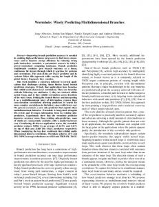
precede the CAM arrays. To accurately compare the power consumption of the pipelined and conventional SL driving, the SL drivers allow the circuit to operate either in the conventional or in the pipelined mode. The dynamic NOR gate, which checks if there is a match in the pipeline stage and disables the following stage, is incorporated into the MLSAs. The output of this NOR gate is shown as signal in Fig. 15. To reduce the number of I/O pins on the chip, the word-lines (WLs), the bit-lines (BLs), and the MLSA outputs are accessed serially though the corresponding shift registers. The SLs are accessed via the BL shift register. The ML shift register latches the outcome of the search for the serial output. Dedicated clocks control all the shift registers. The energy dissipation in the BL and WL shift registers was excluded from the measurements since these shift registers are the auxiliary test structures. Fig. 16 presents the chip microphotograph. The die size is 1.7 mm 1.9 mm. The stability-based MLSA occupies the same die area as the current-saving MLSA, and hence the proposed ML sensing scheme does not impose any area penalty. The area overhead due to the pipelined SLs is 13% compared to the conventional CAM. This overhead is large since the test chip has small sized pipeline stages. In fact, the SL register requires the same area as 11 CAM words, and this area is constant per pipeline stage. Therefore, provided the number of words in the stage is sufficiently larger than 11, the overhead due to the SL registers becomes negligible. The chip testing was performed with an Agilent 93000 digital tester at the University of Toronto. The following section present the test chip measurements and compares them with the simulation results.
Fig. 16. Test chip die photo.
Fig. 17. Simulated I-V characteristic of stability-based MLSA.
A. Stability-Based Sensing Scheme Extensive simulations show that the proposed ML sensing scheme reduces the ML power compared to the other two sensing schemes implemented in the test chip. The chip measurements closely match with the simulation results. As was discussed in Section I, the conductive path from ML to ground in a mismatched cell consists of two minimum sized NMOS transistors in series. The effective resistance of such path, , is approximately 5 k when is between 0 and 500 mV. For convenience, we define this range of as the range of interest, and consider the MLSA behavior only within these limits. Hence, the MLSA’s input resistance was aimed to be (12)
VII. SIMULATION AND MEASUREMENT RESULTS In this section, we first discuss the simulation and measurement results for the stability-based sensing, and its robustness to the PVT variations. Next, we describe the results for the pipelined SL driving.
The I-V transfer curve of the MLSA in Fig. 17 shows that the input resistance is within 10% of the expected value under typical conditions. This plot also confirms that for , which assures that the current into the mismatched MLs is cut off as soon as decays to ground.
TYSHCHENKO AND SHEIKHOLESLAMI: MATCH SENSING USING MATCH-LINE STABILITY IN CONTENT-ADDRESSABLE MEMORIES (CAM)
1979
Fig. 19. Simulated I-V characteristic of stability-based MLSA for PVT corners.
Fig. 18. Simulated impulse response of ML with MLSA in stability sensing.
Fig. 18 presents the impulse responses of the ML system for the case of the match, and for 1- to 3-bit misses. These curves confirm the ML behavior predicted by the -domain system analysis. This set of simulations also reveals, that the excitation bringing to 100 mV and the threshold sensor triggering at 200 mV results in the match time comparable to that of the previous work in [10] and [11]. Therefore, the match decision is made while is well within the range of interest, where the MLSA exhibits the I-V characteristic similar to that of a negative resistance. In fact, the excitation level may be increased to improve the search time for the price of higher energy consumption. In the stability-based sensing, any PVT variations effectively offset the MLSA’s negative resistance from its nominal value. This deviation of the negative resistance may cause an incorrect search result only if the pole of the ML moves to the opposite half-plane. The pole of the matched ML moves to the origin only if the MLSA is off. In this case, the ML is marginally stable, and hence does not reach the threshold level, which causes a false-miss decision. A false-match outcome is possible if the pole of the worst-case miss (1-bit miss) shifts to the RHP, making the ML unstable. A switch of the pole’s half-plane happens if the absolute value of the negative resistance reduces below . In this case, the rate of the energy injection through the MLSA is higher than the rate of the energy dissipation through the mismatched cell resistance , and starts growing. To allow the largest possible deviation of the ML pole without switching the half-plane, the poles of the matched ML and of the ML with 1-bit miss must be equidistant from the origin. The distance between the poles in these two cases is determined by . Therefore, making the resistance of the MLSA equal to achieves the desired pole spacing from the origin. Fig. 19 presents the simulated I-V characteristic of the MLSA for the typical and the worst-case PVT conditions. In addition to the different process corners, the supply voltage was varied by 20% from the nominal value, and the temperature—by 50 C. The shaded area represents the slope of the I-V curve, corresponding to the resistance below , i.e., the false match zone. As the simulations indicate, in the worst case conditions, the MLSA resistance never reaches the critical value. Fig. 20 translates the resistance deviation due to the PVT corners
Fig. 20. Offset of the poles due to PVT variations.
TABLE I MATCH TIME AND ML ENERGY
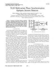
into the corresponding ML pole displacement for the match and the 1-bit miss cases. As we can see, the maximum pole offset is 65% from the nominal value, and the poles remain in the proper half-planes. Hence, the worst-case PVT variations do not alter the system stability, and hence do not cause decision errors. The measurements show that all three ML sensing schemes function correctly at the frequency of 200 MHz. The match time, which is the time from the beginning of the sensing till the results are latched in the ML register, was measured by varying the duty cycle of the system clock. Table I presents the measured results in TT corner with 1.8 V supply at 25 C. The current-race scheme is 9% faster than the remaining two schemes, while the current-saving and the stability-based schemes require the same time to detect a match. Note that we have designed the stability-based sensing scheme to have the same match time as that of the current-saving scheme. Fig. 21 presents the measured energy consumption by the three ML sensing schemes as a function of the number of mismatching bits in a word, . The current-race sensing dissipates the same amount of energy regardless of the number of bitmisses. The current-saving scheme is mismatch-dependent: it allocates more energy to the words with smaller number of mismatching bits. The measurements confirm this trend. With increasing, the energy consumption converges to the constant
1980
IEEE JOURNAL OF SOLID-STATE CIRCUITS, VOL. 43, NO. 9, SEPTEMBER 2008
Fig. 21. ML energy versus number of mismatched bits in a word (TT corner, 1.8 V supply, 25 C).
Fig. 22. Measured ML energy savings (TT corner, 1.8 V supply, 25 C, simulated SL energy).
TABLE II SIMULATED AND MEASURED SL ENERGY
value. In the stability-based sensing, all the mismatch cases receive the same small amount of energy, and only the matched ML gets more energy. Hence, the energy distribution in all three ML sensing schemes agrees with the expected outcome. In fact, as the plot indicates, the stability-based scheme dissipates less energy than the other two schemes for any value of (including match case), i.e., for any search data pattern. Table I compares the measured average ML energy with the simulated energy consumption. The measurements indicate that the stability-based sensing saves 50% of ML energy compared to the current-race, and 30% compared to the current-saving schemes. The measured results are within 10% of the values obtained with simulations, which is a close match. Fig. 22 presents these measured ML energies in a graphical form. B. Pipelined SL Driving The measurements confirm that the chip operates properly in both the non-pipelined and the pipelined modes. With the random search data, 50% of the SLs switch state every clock
Fig. 23. Measured SL energy savings (TT corner, 1.8 V supply, 25 C, stability-based ML sensing).
cycle. This SL activity was used for the energy measurements. The match locations were uniformly distributed among the pipeline stages. Table II presents the measured and the simulated SL energy consumptions in TT corner with 1.8 V supply at 25 C. With the SL register energy included, the measurement results exceed the simulated values by over 35%. Moreover, pipelining increases the SL power, according to the measurements. Further testing revealed that the discrepancy is due to the SL registers between the pipeline stages. Keeping the SL data constant, the energy measured with the SL clock running is 3.4 times higher than expected from the simulations: 0.99 fJ/bit/search vs. 0.29 fJ/bit/search. Hence, in the pipelined mode, the register energy due to clocking makes 42% of the SL energy, while in the non-pipelined mode this portion is 14%. The circuit simulations, intended to find the source of the error, showed that the power of the flip-flops in the SL registers strongly depends on the rise time of the clock. With the increasing rise time of the clock signal, the flip-flop power significantly increases. Hence, the energy loss in the SL registers causes the increase in the energy consumption in the pipelined architecture, compared to the conventional CAM. In practical systems, the size of the pipeline stages is large, and the energy consumption by the SL registers is small compared to the SL driving energy. To emulate such a CAM, the register energy is subtracted from the total SL energy. This allows to observe the energy saving effect of pipelining, even with highpower SL registers. Table II also shows the measurement results with the SL register energy excluded. Thus, the pipelining reduces the SL energy by 32% compared to the non-pipelined configuration, which is close to the expected 33% savings for the three-stage pipeline. Fig. 23 presents these savings graphically. The test chip measurements validate the energy saving effect of pipelining the SLs in CAM. To keep the energy overhead due to the SL registers small, the size of the pipeline stages should be large. The energy dissipation due to the SL registers becomes more critical in the designs with fewer words per pipeline stage. VIII. CONCLUSION We presented two techniques for reducing CAM power: the stability-based match sensing scheme and pipelined SL driving. In the stability-based sensing, we exploit the system stability of the MLs to minimize the amount of energy delivered to mismatched MLs. This sensing scheme reduces the ML power by 50% compared to the current-race scheme [10], and by 30%
TYSHCHENKO AND SHEIKHOLESLAMI: MATCH SENSING USING MATCH-LINE STABILITY IN CONTENT-ADDRESSABLE MEMORIES (CAM)
compared to current-saving ML sensing [11]. We also showed that the stability-based sensing technique approaches the minimum achievable ML power, and that the scheme is robust to PVT variations. The pipelined SL driving scheme segments CAM in the direction of the search-word distribution to reduce the average number of active CAM blocks, thus saving power. This SL driving technique saves up to 50% of CAM power compared to conventional SL driving. The measurements of a test chip fabricated in 0.18 m CMOS process confirm the power savings of the stability-based sensing and pipelined SL driving. ACKNOWLEDGMENT The authors thank K. Pagiamtzis and M. van Ierssel for their valuable suggestions on design and testing, and H. Tamura for insightful discussion and advice. REFERENCES [1] T. Kohonen, Content-Addressable Memories, 2nd ed. Hoboken, NJ: Springer-Verlag, 1987. [2] L. Chisvin and R. J. Duckworth, “Content-addressable and associative memory: Alternatives to the ubiquitous RAM,” IEEE Computer, vol. 22, no. 7, pp. 51–64, Jul. 1989. [3] K. E. Grosspietsch, “Associative processors and memories: A survey,” IEEE Micro, vol. 12, no. 3, pp. 12–19, Jun. 1992. [4] L.-Y. Liu, J.-F. Wang, R.-J. Wang, and J.-Y. Lee, “CAM-based VLSI architectures for dynamic Huffman coding,” IEEE Trans. Consumer Electron., vol. 40, no. 3, pp. 282–289, Aug. 1994. [5] C.-Y. Lee and R.-Y. Yang, “High-throughput data compressor designs using content addressable memory,” IEE Proc.—Circuits, Devices Syst., vol. 142, no. 1, pp. 69–73, Feb. 1995. [6] S. Panchanathan and M. Goldberg, “A content-addressable memory architecture for image coding using vector quantization,” IEEE Trans. Signal Process., vol. 39, no. 9, pp. 2066–2078, Sep. 1991. [7] P. Gupta and N. McKeown, “Algorithms for packet classifications,” IEEE Network, vol. 15, no. 2, pp. 24–32, Mar./Apr. 2001. [8] H. J. Chao, “Next generation routers,” Proc. IEEE, vol. 90, no. 9, pp. 1518–1558, Sep. 2002. [9] K. Pagiamtzis and A. Sheikholeslami, “Content-addressable memory (CAM) circuits and architectures: A tutorial and survey,” IEEE J. SolidState Circuits, vol. 41, no. 3, pp. 712–727, Mar. 2006. [10] I. Arsovski, T. Chandler, and A. Sheikholeslami, “A ternary contentaddressable memory (TCAM) based on 4T static storage and including a current-race sensing scheme,” IEEE J. Solid-State Circuits, vol. 38, no. 1, pp. 155–158, Jan. 2003. [11] I. Arsovski and A. Sheikholeslami, “A mismatch-dependent power allocation technique for match-line sensing in content addressable memories,” IEEE J. Solid-State Circuits, vol. 38, no. 11, pp. 1958–1966, Nov. 2003. [12] N. Mohan et al., “Match line sense amplifiers with positive feedback for low-power content addressable memories,” in Proc. IEEE Custom Integrated Circuits Conf., 2006, pp. 297–300.
1981
[13] K. J. Schultz, “Content-addressable memory core cells: A survey,” Integration, The VLSI J., vol. 23, no. 2, pp. 171–188, Nov. 1997. [14] G. Kasai, Y. Takarabe, K. Furumi, and M. Yoneda, “200 MHz/200 MSPS 3.2 W at 1.5 V Vdd, 9.4 Mbits ternary CAM with new charge injection match detect circuits and bank selection scheme,” in Proc. IEEE Custom Integrated Circuits Conf., 2003, pp. 387–390. [15] K. Pagiamtzis and A. Sheikholeslami, “A low-power content-addressable memory (CAM) using pipelined hierarchical search scheme,” IEEE J. Solid-State Circuits, vol. 39, no. 9, pp. 1512–1519, Sep. 2004. Oleksiy Tyshchenko received the B.A.Sc. degree (with honors) in electrical engineering from the Division of Engineering Science in 2004 and the M.A.Sc. degree in electrical and computer engineering in 2006, both from the University of Toronto, Toronto, ON, Canada. He is currently working toward the Ph.D. degree in the Department of Electrical and Computer Engineering, University of Toronto. In 2006, he spent 6 months as an intern with Fujitsu Labs of America working on circuit design for high-speed signaling applications. His research interests are in architecture and circuit design for content-addressable memories (CAM). He is also interested in the design of clock and data recovery (CDR) circuits for high-speed signaling systems. Mr. Tyshchenko has held the Natural Sciences and Engineering Research Council of Canada (NSERC) postgraduate scholarship and the Ontario Graduate Scholarship (OGS).
Ali Sheikholeslami (S’98–M’99–SM’02) received the B.Sc. degree from Shiraz University, Shiraz, Iran, in 1990 and the M.A.Sc. and Ph.D. degrees from the University of Toronto, Toronto, ON, Canada, in 1994 and 1999, respectively, all in electrical and computer engineering. In 1999, he joined the Department of Electrical and Computer Engineering, University of Toronto, where he is currently an Associate Professor. His research interests are in the areas of analog and digital integrated circuits, high-speed signaling, and VLSI memory design. He currently supervises two active research groups in the areas of high-speed signaling and VLSI memories. He has collaborated with industry on various VLSI design research in the past few years, including work with Nortel and Mosaid, Canada, and with Fujitsu Labs of Japan and America. He spent his 2005–2006 research sabbatical year with Fujitsu Labs of Japan and Fujitsu Labs of America. Dr. Sheikholeslami served on the Memory Subcommittee of the IEEE International Solid-State Circuits Conference (ISSCC) from 2001 to 2004, and on the Technology Directions Subcommittee of the same conference from 2002 to 2005. He currently serves on the Wireline Subcommittee of ISSCC. He presented a tutorial on ferroelectric memory design at ISSCC 2002 and a tutorial on high-speed signaling at ISSCC 2008. He was the program chair for the 34th IEEE International Symposium on Multiple-Valued Logic (ISMVL 2004) held in Toronto, Canada. He has received the Best Professor of the Year Award four times since 2000 by the popular vote of the undergraduate students in the Department of Electrical and Computer Engineering, University of Toronto. In 2006, he received the Early Career Teaching Award in recognition of his “superb accomplishment in teaching” from the Faculty of Applied Science and Engineering at the University of Toronto. He is a registered professional engineer in the province of Ontario, Canada.