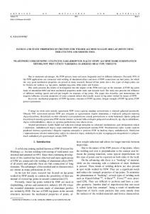
Material flow in heterogeneous friction stir welding of aluminium and copper thin sheets I. Galva˜o*, R. M. Leal, A. Loureiro and D. M. Rodrigues The aim of this investigation was to study material flow during dissimilar friction stir welding of AA 5083-H111 to deoxidised high phosphorus copper plates of 1 mm thickness. The welds were performed using different tool geometries and welding parameters. The positions of the copper and aluminium plates, relative to the advancing and retreating sides of the tool, were also changed. It was found that the tool geometry and relative position of the plates deeply influence the morphology of the aluminium and copper flow interaction zones, influencing the distribution of both materials in the weld and the formation of intermetallic compounds. The material accumulated under the tool during welding was found as another important aspect determining weld morphology. Keywords: Aluminium, Copper, Welding tool, Material flow
Introduction Joining dissimilar materials, such as aluminium and copper (Al/Cu) or aluminium and steel (Al/Fe–C), is of great interest in engineering and design applications. Nevertheless, fusion welding of materials with very different melting temperatures and high chemical affinity at elevated temperatures, which gives rise to the formation of brittle intermetallic compounds, makes such joining very difficult and the quality of the welds very poor. In this context, friction stir welding (FSW), which enables the joining of materials at temperatures lower than their melting temperatures, is a promising technology for joining metals with very different chemical and physical properties.1 However, the use of the process in this type of application is not fully explored, and there are several issues that still require extensive research, such as the development of accurate welding procedures and, for the case of Al/Fe–C joining, the development of adequate FSW tool materials.2 Since the main issues regarding the weldability of Al/Cu and Al/Fe–C systems, such as the mixture of both base materials in the solid state and the formation of brittle intermetallic compounds, are common to both dissimilar systems and because the joining of aluminium to copper does not require the production of tools from very expensive materials, this system is considered very interesting for research purposes. However, the limited data already published concerning FSW of aluminium to copper highlight the extremely high difficulty in obtaining welds absent of defects and the scarcity of results regarding the joining of very thin plates.3–7 As a matter of fact, obtaining non-defective welds in very thin plates, with
CEMUC, Department of Mechanical Engineering, University of Coimbra, Coimbra, Portugal *Corresponding author, email
[email protected]
excellent surface finishing and plastic properties, which makes them able to be processed by plastic deformation, represents an additional challenge in the application of this process. In FSW research, the study of metal flow around the tool during welding is very important to improve process productivity and weld properties. Flow visualisation studies have already been conducted by several authors using different techniques: introducing marker materials into the weld line, using etching contrast to enhance the flow patterns in the weld, welding dissimilar materials and performing numerical simulation studies.8–11 Despite the limitations associated with all the techniques used, which are well documented in the literature, the main metal flow mechanisms have already been established, being found that vertical, straight through and rotational flows of plasticised material take place in the vicinity and around the tool, dragging the bulk of the stirred material to a final position behind its original position. In the wake of the weld, behind the travelling tool, material deposition takes place layer by layer, resulting in the formation of the banded structure of the nugget. Variations in tool geometry and/or plate thickness do not change the main flow mechanisms, but greatly influence the amount of material dragged by the shoulder or by the pin, from the retreating and advancing sides of the tool, as well as the periodicity of the deposition at the trailing side of the tool, which, in turn, influences the final morphology of the weld. These aspects can be deduced by comparing the results from Leal et al.,11 which studied the influence of the shoulder geometry on material flow in dissimilar FSW of very thin aluminium plates, with those from previous authors working on FSW of thick plates. Leal et al.11 compared the material flow during FSW using scrolled and conical shoulder tools. They reported that, in FSW of very thin AA 5182/AA 6016 plates (1 mm thick), the shoulder influence area extends
ß 2010 Institute of Materials, Minerals and Mining Published by Maney on behalf of the Institute Received 21 April 2010; accepted 21 July 2010 DOI 10.1179/136217110X12785889550109
Science and Technology of Welding and Joining
2010
VOL
15
NO
8
654
Galva˜ o et al.
through the entire plate thickness, for both types of tools. They also observed material transported by the shoulder from the advancing to the retreating side, all around the tool, when using the scrolled geometry. For the conical geometry, they observed that the shoulder action depth was different at the leading and trailing sides of the tool. Ahead of the pin, the shoulder influence area extends throughout the thickness, encompassing the pin influence area and causing, at each rotation, layers of the advancing side material to enter a shear layer surrounding the pin. At the rear of the probe, the shoulder influence area is restricted to the top of the weld, promoting the transport of the retreating side material to the advancing side of the tool, where it also enters in the inner shear layer surrounding the pin. An analysis similar to that performed by Leal et al.11 was conducted during the present study, in order to characterise the material flow mechanisms during joining of materials with very different chemical, mechanical and physical properties. Namely, the influence of the tool geometry and welding parameters on material flow during dissimilar FSW of 1 mm thick plates of 5083H111 aluminium alloy to deoxidised high phosphorus (DHP) copper was analysed.
Experimental Materials and welding process In the present study, 1 mm thick plates of oxygen free copper with high phosphorous content (Cu-DHP, R240) and 5083-H111 aluminium alloy (AA 5083-H111) were friction stir butt welded. Four types of welds were performed between the base metals using tools with two different shoulder geometries [conical and scrolled (Fig. 1)] and varying welding parameters (traverse and rotation speeds) in an ESAB LEGIO FSW 3U apparatus. Henceforth, in the text, the welds will be labelled C (conical series) or S (scrolled series) according to the tool used in their production. In the C series of welds, a 14 mm diameter conical tool with a 3u shoulder cavity and a 3 mm diameter cylindrical probe was used. In the S series welds, a tool with a 14 mm diameter scrolled shoulder and a 3 mm diameter cylindrical probe was used. The tilt angles were 2u for the conical tool and 0?5u for the scrolled shoulder tool. The C series welds were performed under load control (700 kg), and the S series welds were carried out under position control, with 0?05 mm penetration depth. Table 1 displays the full set of welding conditions considered in this study. With reference to the testing conditions, the nomenclature adopted in the text to classify the welds of each series will identify the rotational and welding speeds used, as well as the material positioned at the advancing side of the tool. Thus, the C_1000_16_Cu weld is a C series weld performed with the conical tool, having rotational and welding speeds of 1000 rev min21 and 160 mm min21 respectively and with the copper plate positioned at the advancing side of the tool. When the aluminium alloy was positioned at the advancing side of the tool, the last two alphabets in the nomenclature will be Al, as shown in Table 1.
Equipments, techniques and methods After welding, qualitative and quantitative macroscopic inspections of the weld surfaces were performed by
Material flow in heterogeneous FSW of Al and Cu thin sheets
1 Scrolled tool
means of visual inspection and image data acquisition respectively using ARAMIS optical analysis equipment. Transverse and horizontal cross-sectioning of the welds was also performed for metallographic analysis. The samples were prepared according to standard metallographic practice and differentially etched in order to enable the identification of the different materials in the weld. ‘Modified Poulton’s reagent’ was used to enhance the aluminium and a solution of 5 mL H2O2 in 50 mL NH4OH to enhance the copper. Metallographic analysis was performed using a Zeiss HD 100 optical microscope (Carl Zeiss Inc., Jena, Germany) and a Zeiss magnifier. Microhardness measurements were performed using a Shimadzu microhardness tester (Shimadzu Corp., Kyoto, Japan), with 200 g load and 15 s holding time. The elementary chemical composition (Al/Cu) was determined using electron probe microanalysis in a Cameca Camebax SX50 apparatus (Cameca, Gennevilliers, France). Finally, XRD analysis was performed using a PANalytical X’Pert PRO X-ray diffractometer (PANalytical, Almelo, The Netherlands).
Results Scrolled weld series Results of the macroscopic inspection of the S-750_ 16_Cu weld are shown in Fig. 2. Specifically, Fig. 2a shows a picture of the weld crown, and Fig. 2b shows an image of the same surface, but acquired with an image system that enables the variations in depth inside the weld to be determined. Thus, on the scale at the right side of Fig. 2b, z50 corresponds to the base material plate surface, the negative values in the scale correspond to points inside the weld from which material was removed and the positive values correspond to points inside the weld where material was accumulated. As illustrated in Fig. 2a and b, the S-750_16_Cu weld Table 1 Welding parameters used to produce the welds Weld
w, rev min21
v, mm min21
Advancing side metal
S_750_16_Cu C_1000_16_Cu C_750_16_Al C_1000_25_Al
750 1000 750 1000
160 160 160 250
Cu-DHP Cu-DHP AA 5083 AA 5083
Science and Technology of Welding and Joining
2010
VOL
15
NO
8
655
Galva˜ o et al.
Material flow in heterogeneous FSW of Al and Cu thin sheets
2 a crown appearance and b thickness spectrum of S weld
displayed good appearance with highly localised surface irregularities, not exceeding 0?2 mm in depth, which indicates some homogeneity in material deposition at the weld surface. Figure 3 shows a transverse cross-section of the S750_16_Cu weld in which the pin and shoulder influence zones are identified. A tongue of grey material going upwards through the advancing side of the weld is clearly visible in this cross-section. A similar weld feature was observed by Leal et al.11 in AA 6016/ AA 5182 dissimilar welds performed with the same type of tool. Magnifications of the weld features indicated in Fig. 3 by two red rectangles are shown in Fig. 4. These pictures show that the grey tongue in the Al/Cu weld is surrounded by copper and that inside the pin influence area, at the right side of the tongue, there is a clear interface between the two base materials. The very high hardness values displayed in Fig. 4a show the extreme brittleness of the grey tongue. Chemical analysis, followed by XRD, indicated that the tongue resulted from intense Al/Cu mixture, which led to the formation of large amounts of intermetallic compounds, namely, large amount of CuAl2 and some Cu9Al4. On the other hand, the chemical and XRD analysis also showed that no material mixing or intermetallic formation occurred at the base material interface displayed in Fig. 4b. Figure 5 shows macrographs of four horizontal crosssections of the weld, sampling the zone near the final hole left by the tool at 0?80, 0?71, 0?54 and 0?45 mm from the weld root. The positioning of these sampling planes relative to the weld thickness is indicated in Fig. 4a. Analysing the 0?54 and 0?45 mm cross-sections, as shown in Fig. 5c and d, it is possible to observe a layer of grey material surrounding the hole left by the pin, with deep cracks, which shows its extreme brittleness. This inner layer is surrounded by copper, which, according to the pictures, was dragged by the shoulder from the advancing side of the weld, around the tool, and it was extruded against the inner shear layer at the back of the tool. The aluminium alloy, which is the retreating side material, is only dragged into the inner grey layer at the top of the weld, as shown in Fig. 5a and b. In these pictures, it is possible to observe that the aluminium alloy has been pushed towards the advancing side of the weld, at the back of the tool, where materials from all
the layers are pushed into the inner shear layer (1 in Fig. 5a and b). These materials are mixed around the pin and flow, from the top to the bottom of the weld, where the mixture sloughs off in the wake of the weld after one or more rotations, giving rise to the grey tongue visible in the transverse section (2 in Fig. 5a and c). The copper layer, which is dragged by the shoulder around the tool, is extruded against the inner layer at the trailing side of the tool (3 in Fig. 5c). Finally, the aluminium, from the retreating side (4 in Fig. 5c), is extruded against the copper layer giving rise to the interface shown in Fig. 4b. It is important to emphasise that these flow mechanisms are similar to those reported by Leal et al.11 in dissimilar joining of very thin aluminium plates.
Conical weld series Figure 6 shows results of the macroscopic inspection of C welds, demonstrating that all the weld crowns are formed of a thick layer of irregularly distributed material. From Fig. 6b, it is possible to observe that for the welds performed with the aluminium on the advancing side (C-750_16_Al and C-1000_25_Al) large amounts of material were dragged from the retreating (blue areas, 0?45 mm deep) to the advancing side of the tool, where it is accumulated (red areas). Figure 7 shows transverse cross-sections of these welds, which demonstrate that, independent of the welding parameters, the copper is pushed from the retreating to the advancing side of the weld, and the aluminium is expelled from the under shoulder area, giving rise to massive aluminium flash. The onion ring structure characteristic of the welds performed with conical shoulder tools was not formed in these cases. However, under the upper copper layer, at the advancing side of the weld, a very small area of aluminium lamellae with small copper particles embedded on it is formed. XRD analysis indicated that no material mixing or intermetallic formation occurred in this lamellar structure. Figure 8 illustrates a transverse cross-section of the C1000_16_Cu weld performed with the copper plate at the advancing side of the tool. As for the previous welds, the weld nugget does not exhibit the classical onion ring structure. The most important features of these welds, outlined in the picture by red rectangles, are the presence of an aluminium layer, which was pushed from the retreating to the advancing side of the weld (1), a clear boundary between the aluminium and copper at the retreating side (2), inside the pin influence area, and
3 Transverse cross-section of S-750_16_Cu weld
Science and Technology of Welding and Joining
2010
VOL
15
NO
8
656
Galva˜ o et al.
a
b a material tongue; b Al/Cu interface 4 Magnifications of zones signalised in Fig. 3
finally, the presence of a dark region extending from the pin influence area to the advancing side of the weld (3). Figure 9 shows a magnification of the dark region (3) in Fig. 8. Since this picture was taken from the weld without etching, the region displays grey and yellow tones. The hardness measurements presented in the figure and the presence of a crack in the region where the highest hardness values were registered (700 HV0?2) are indicative of great brittleness. A quantitative chemical analysis inside the area indicated in Fig. 9 by a red rectangle identified the presence of both copper and aluminium, which indicates that this area resulted from intense material mixing during welding. XRD analysis identified Cu9Al4 in this weld zone. Macrographs of four weld horizontal cross-sections were registered after polishing, sampling the zone near the final hole left by the tool at 0?74, 0?66, 0?61 and
Material flow in heterogeneous FSW of Al and Cu thin sheets
0?41 mm from the weld root. These are shown in Fig. 10. The positioning of these sampling planes relative to the weld thickness is indicated in Fig. 9. From the pictures, it can be concluded that the shoulder influence area was restricted to the top surface of the weld, at the rear of the tool, where it promotes the transport of aluminium from the retreating to the advancing side of the tool. In fact, in the 0?74 and 0?66 mm horizontal sections (Fig. 10a and b), at the rear of the tool, mixed and intercalated layers of aluminium and copper are visible all across the shoulder influence area. On the other hand, in front of the weld, only a very thin layer of copper is visible, which was dragged from the advancing to the retreating side of the weld, inside the pin influence area. In the 0?61 mm horizontal section (Fig. 10c), the quantity of aluminium dragged to the advancing side diminishes drastically. In the lower plane, at 0?41 mm (Fig. 10d), the probe is completely surrounded by copper, and no signs of mixing are visible. Therefore, the mixing of both base materials occurs in the upper half of the plate thickness, in the under shoulder area, giving rise to the dark region shown in Fig. 8. There is also no onion ring structure discernible in this Al/Cu weld. The Al–Cu mixing area, at the upper middle thickness, displays morphology with fluid-like patterns, as can be seen by analysing Fig. 9. The analysis of the material accumulated in the under shoulder cavity during the process, which was collected at the end of the welding operation (Fig. 11a), also showed fluid-like patterns, as can be observed in Fig. 11b. High hardness values, of the order of those registered in the intermetallic structure of the welds (Fig. 9), were measured for this material, as displayed in Fig. 11b. XRD analysis detected the presence of Cu9Al4. The presence of this intermetallic compound, which has a melting temperature of 1030uC,4,12,13 much higher than the usual FSW temperatures, suggests that an accumulation of solid intermetallic occurs under the shoulder, with detrimental effects on weld surface finishing, as shown in Fig. 6. XRD analysis also showed that the upper weld layer, as shown in Fig. 6a, has large amounts of Cu9Al4 and CuAl2. Since the CuAl2 intermetallic phase has a lower
5 Horizontal cross-sections of S-750_16_Cu weld at a 0?80 mm, b 0?71 mm, c 0?54 mm and d 0?45 mm from root
Science and Technology of Welding and Joining
2010
VOL
15
NO
8
657
Galva˜ o et al.
6 a crown appearance and b thickness spectrums of C welds
melting temperature than the FSW process temperatures (