MATLAB BASED REMOTE CONTROL USING COM OBJECT Michal Sedlák and Katarína Žáková Faculty of Electrical Engineering and Information Technology, Slovak University of Technology, Ilkovičova 3, 812 19 Bratislava, Slovakia
[email protected],
[email protected]
6th
Int. Conference on
Emerging e-learning Technologies and Applications
Abstract. The paper presents one way of remote control of real experiments. The introduced approach includes Matlab software environment, Apache web server and mod_python. Firstly, there is described how the Matlab COM object is connected to Apache server and mod_python module as well as solution of problems that are common to communication between COM and multi threaded applications like Apache web server. The procedure is verified on the remote control of the magnetic levitation model that is done using Python implementation. The created GUI offers user to change the default controller by a user defined one, full and secure access to the command line interface of the Matlab, as well as to the dynamically generated SVG graph.
The High Tatras, Keywords. remote control, magnetic levitation, python, Matlab Slovakia September 11-13, 2008
INTRODUCTION In the last years improvement of education is very often connected with Internet. One can meet with concept of elearning, online education, Internet based education, etc. Following this tendency many universities started to develop online study materials and interactive study objects already a few years ago. In the area of automatic control the development was also devoted to the development of virtual and remote laboratories. Teachers are encouraged to design control engineering online courses that combine theoretical issues and practical activities. Internet in this way offers high flexibility since the course can be improved night and day and all parts of the web-based course can be reachable from any location and in any time. Thanks to permanent online connection activities can be available close to 24/7. In addition, building of online labs helps to spare financial costs. However, the main effect consists in the fact that they can be available to more students. Talking about control education experiments can be devoted to several problems starting from modeling of dynamical systems, identification, simulation animation and ending by control of remote experiments. Contrary to the virtual laboratory, by real experiments (i.e. also in the remote laboratory) students realize that control algorithm designed for the simulated simplified mathematical model may not work properly. It is necessary to take into account presented noise, possible delays and unmodelled dynamics. In spite of the fact that the building of remote laboratory requires to develop the whole infrastructure of the clientserver application, the only thing that is needed for student access to the remote lab is usually a web browser.
PROBLEM DESCRIPTION For illustration purposes we decided to use magnetic levitation model that is provided by Humusoft company [10]. The model of magnetic levitation demonstrates control problems associated with nonlinear unstable systems. The
system consists of a coil levitating a steel ball in magnetic field. Position of the steel ball is sensed by an inductive linear position sensor connected to A/D converter. The coil is driven by a power amplifier connected to D/A converter, as is shown in Fig. 1. The basic control task is to control the position of the ball freely levitating in the magnetic field of the coil. The magnetic levitation system is a nonlinear dynamic system with one input (current flow which influences magnetic field intensity) and one output (position of the steel ball).
Fig. 1: Magnetic levitation model principle The motion equation is based on the balance of all forces, i.e. gravity force Fg, electromagnetic force Fm and the acceleration force Fa
F a= F m − F g
F g = mg
Fm =
i 2kc
( x − x 0 )2
F a= m x¨
(1) (2) (3) (4)
i - coil current [A] kc - coil constant mk - ball mass [kg]
x - ball position [m] x0 - coil offset [m] g -gravity constant [ms-2]
This model can be controlled either by analogue or by digital controllers. Students can exercise the manual control or some non-analytical way of controlling, e.g. fuzzy control. Another possibility is to use linear control (PD and PID control based e.g. on the generalized method by Ziegler and Nichols) or nonlinear control design (based e.g. on the exact linearization method, control of constrained systems, etc.). However, in this way, it is necessary to start with identification of an unstable nonlinear system (steady state plant characteristic – curve fitting, step response analysis requiring closed loop stabilization of the starting position and elimination of the measurement noise by multiple measuring).
In the case of magnetic levitation, the plant has to be controlled using the sampling period close to 1 ms. It is really a very fast dynamics and it brings very high demands on the quality of connection. Since we are not able to manage application latencies that can occur over the Internet for this plant, this approach cannot be used.
Our aim is to control the introduced plant over Internet. In spite of the fact that several approaches can be used, there exist two basic concepts: Fig. 3: Remote control of local control •
The plant is controlled remotely, i.e. the control signal is computed on the client side and transfered via internet.
•
The plant is controlled locally whereby this local control is influenced remotely.
The first approach (Fig. 2) enables remote control of the plant using the client application that sends control signal to the remote experiment and receives the output from the plant directly via Internet.
The second approach is sketched in Fig. 3. It keeps the whole control on the server side. The application has only two communication channels. One of them serves for receiving data from the experiment and the control channel is used to send commands to the experiment. In this approach the remote user sets control parameters, selects or uploads control algorithm and starts the experiment. As it can be seen in Fig. 3, the whole control loop is on the server side and the user has only limited possibilities to modify the running experiment. The client application is able to request online data and to change parameters of the experiment, but it is not able to change local control algorithm on the fly. It can be modified only in the moment of creation of experiment, i.e. before the experiment is started. This approach enables to prepare and run experiments and to follow current running simulation. Since parameters (gains, constants, etc.) that do not change the structure of running experiments can be customized, we have the possibility to tune experiment on the fly.
REQUIREMENTS Our main aim was to control the remote magnetic levitation plant connected to PC with Matlab environment. The solution should be versatile and accessible in any web browser. We intended to have a client side with dynamic visualization that will provide the user with the actual visual information and the possibility to change attributes on the fly. Fig. 2: Direct control via internet As it was already mentioned the whole control algorithm runs on the remote client and after all computations are done, the computed control variable is transferred to the plant via Internet using the agreed protocols. This means that the remote user has the whole control process under own control and therefore he or she must have all needed information.
First of all we need a functional local control of the experiment. The plant was designed to work with the Matlab software. The documentation and software drivers for Matlab were supplied directly by the vendor. This made a choice of the back end very straightforward and some requirements become more clear. Since Matlab was intended to be the base platform for control, we used its embedded tools for real-time experiments - Real Time Workshop. We needed to communicate with Matlab fast
enough to provide the dynamic visualization. We wanted to produce easy customizable and modular client-server application that is stable, secure and fast enough for our purposes. We tried to accomplish our aims observing standards dealing with Internet communication and web. The standards can guarantee faster development and interaction with 3rd party functions and modules, as well as future development. Realization of all these requirements leads to the robust remote control application, that can be extended to any plant even it was developed having the magnetic levitation plant in mind.
REALIZATION Firstly, we have to specify the server platform. As it was already told, we decided to use Matlab for communication with the plant. The plant was connected to PC with data acquisition card MF264 distributed by Humusoft. For the local control of the plant the Matlab Real Time Workshop was used. After the stable local control was realised in Simulink, we started to plan how to control the plant over the Internet. We decided to realize the solution that is sketched in Fig. 3. In spite of the fact that it also brings some limitations, they are not so important and this solution gives us all required interactivity. Now, let us go to the description of the server and the client application (Fig. 3). One of basic requirements is accessibility and versatility of the solution without any additional custom software. For this purpose we can use one of the most utilized services of the Internet, i.e. World Wide Web. The Web service is based on the HTTP over TCP/IP. Since the web is commonly used Internet service, the most of the desktop operating systems have included a web browser in their basic installation. However, the problem is that it doesn’t always support all necessary standards. The new generation of web browsers, like Mozilla Firefox, Opera or Safari, has already implemented the support of standards that we need, e.g. for displaying and interacting with content and for dynamic data visualisation. These browsers are free or opensource, so they are accessible for everybody and for majority of software and hardware platforms. Internet Explorer displays SVG files using Adobe SVG Viewer plugin [13]. Thanks to implemented advanced standards the web browser becomes a very powerful client for remote control. It is able to fulfil all our requirements. Apache and mod_python The Web client-server architecture is one of the best solutions for the Internet communication. Web browser gets all its content from the web server. The use of stable and robust web server guarantees the stable application with low maintenance effort. Since we need to work with Matlab, the server should be able to connect to, or to create a controlled Matlab session. It is to note that the fast response is demanded. In addition, we need to visualize changes of the plant inputs and outputs dynamically. From these reason we chose the Apache web server as a base of the solution and mod_python module as the tool to create application. Mod_python module allows us to create application in
Python language and to create persistent connection to the Matlab session via Matlab COM object. Matlab COM and mod_python The interprocess communication with Matlab is ensured by commonly used Matlab Engine. On the Windows Platform the Matlab Engine communication is provided by Matlab COM object. We decided to communicate directly with Matlab through Matlab COM object, because libraries for Matlab Engine were supplied only for C and Fortran. In [9] we compared communication with Matlab COM using PHP and Python and we have found out that Python is more suitable for our goal, because of better internal serialization and possibility for thread safe co-initialization of the COM. We used the function pythoncom.Coinitialize() from PyWin32 extension that helped us to meet our requirements and the easy development of the application. Mod_python has also included functions for web sessions and for http. In web application the web session handling is important because of the nature of http communication. This communication is fully asynchronous and the majority of session information is stored on the server side. It means that server has to assign each request to the appropriate session. The problem was to trace server side session, because of threaded nature of web servers. However, mod_python’s mod_python.Session object is the efficient answer to this problem. It implements persistent objects that are accessible all the time. In addition, Python has implemented serialization that allows storing created Matlab COM instance in the session object. Storing the whole COM instance in the session made the stored instance persistent and easy accessible across all requests. The main consequence of a good session support is that the COM object, as well as the Matlab session, is accessible over the whole experiment run. It enables to request current simulation data, or to modify parameters of the running experiment without any need to retrieve the session, to stop or to recompile the simulation scheme, until we generate changes that alter a scheme structure. Matlab schemes To access the already mentioned required features we have to create the Simulink scheme with predefined blocks allowing to dump current simulation data to the client and to replace the default controller with the custom one. The Simulink scheme has to be created with Real Time Windows Target blocks used for accessing the plant. Next we added there blocks to normalize the plant input (u) and the plant output (y). The data collecting is done by the Scope block via the Matlab function buf=get_param('ModelName/ScopeName', 'CopyDataBuffer') that enables to access the current data from the Scope on the fly. This function reads current Scope buffer and returns it to the Matlab workspace where is available for the next use. For the visualization we need only actual value of w (desired value, set point) and y, i.e. it is necessary to set the Scope property “Limit data points to last” to one. It limites the length of the stored variable to the last actual value. If
we need to increase the number of monitored signals, we just include Mux block before the Scope block. Since we require replacing the default controller, we enclosed it in one block named “Regulator”. Actually, we created two block schemes. In the first one we have the controller with control error e as input and control action u as output (Fig 4).
Fig 4: Simple simulation scheme This scheme can be used for classical simple design of controllers. The second structure has two variables w (desired value) and y (plant output) as inputs and u (control signal) as output (Fig. 5).
Fig. 5: Advanced simulation scheme This scheme can be used for more complicated control structures that have alternative internal structure (based e.g. on derivative of y). The presented approach separates the control logic depending on the plant from the other independent parts that visualize signals and communicate with Matlab. The customization of the application for any other SISO plant consists only in the replacement of the basic Simulink scheme. It is necessary to take into account only a few basic requirements that are connected with its development for control of real experiments. User defined controller In general, there are two basic concepts for allowing user to use custom blocks. The first concept consists in the fact that the controller block in the basic scheme is considered as a reference. The second approach enables to replace the controller block in mdl file with a block from user that is placed in the user defined mdl file with the name “Regulator”. We prefer the second approach because of limitations for using referenced models with Real Time Workshop [11]. Parsing. To allow using the custom defined controller we need to replace the controller from the basic scheme by controller from the user scheme. That means, we need to
exchange a block from one mdl file with another block from the other file. For this purpose it is necessary to know the exact structure of the mdl file [11]. The mdl file is a structured text file that contains keywords and parametervalue pairs that describe the whole scheme. It is divided to sections whereby the System section is the most important. However, since this section is the subsection of the Model section, we have to work with whole file. After knowing the internal structure of the documents, we can start to work on parsing of the mdl files. At the development of the parsing library we came from the simulinkparser.py [14] where the functionality was increased. The created script is based on pyParsing module [15] with implemented methods for easy parsing of the files. After some customization we created Python module that was able to parse mdl file to the nested list recursively. The nested list is able to hold information about the structure of the scheme and Python has tools for efficient processing of these types of objects. Then, methods for searching blocks by name, and for recursive copy and replace of any block with its nested blocks and parameters were prepared. This tool gives the possibility to replace blocks in internal representation of the scheme. In this way it is possible to take the file with the basic mdl scheme and to replace the whole block named “Regulator” with a block with the same name from the user defined mdl file. This block can be a simple block but also a complicated block with nested sub-blocks. The replacement algorithm will take care about all nested objects and references. Reconstruction of mdl file. After successful creation of the list combined from two mdl files, the reconstruction of final mdl file has to be done. This step is necessary because the internal structure of the nested list (our working format) is not the same as the mdl file format. However, the nested list structure matches with the mdl file. Therefore we created method that wraps and prints this nested list in to a file in mdl file format. Created files can be used in Simulink to run experiments. Main advantage of taking only controller block from the user scheme consists in the fact that it leads to the zero configuration on the client side. All properties needed for successful compilation are inherited from the basic scheme which is used as a template for the final scheme. It means that user does not need any knowledge of Real Time Workshop parameters and requirements. Graphical User Interface (GUI) For the user interaction with the remote system the web application was created (Fig. 6). On its left side there is the main menu, where user can choose an action, like to upload controller, to compile the final scheme or to start prepared simulation. User can choose between simple and advanced interface. In the simple mode, he or she can set only the simulation time. In advanced mode the user gets the interactive AJAX based interface with the access to the Matlab command line interface. It gives user the full access to the Matlab command line and the user is able to set parameters of the simulation and change variables of the model on the fly. It is to note that on the fly changes are allowed only for parameters that do not change structure of the scheme.
In both modes (simple and advanced) user can see results using the dynamic graph and after simulation he or she can download experimental results to the local file.
interactivity of the generated graphics, e.g. signalize status of data, or update current data in time. In addition, the design of SVG files allows using SVG editor that is very comfortable. We need to draw a graphical dependence. First of all, it is necessary to create a SVG file with graph. The static parts of the graph as grid and axes can be drawn by free SVG editor Inkscape. Then, the SVG attribute viewBox [12] has to be created. It sets the virtual resolution of the image (it is defined by 4 values: horizontal and vertical origin and virtual width a height of the graphical area). Inside of SVG graphics it is possible to define dynamical elements of the object, e.g. error messages and finally the polyline elements. Since it has to be influenced by actual numerical data it has to be notified by its own ids:
Fig. 6: Advanced GUI Security Since the remote user has the full access to the Matlab command line and in this way to the whole set of commands that could make harm to the system, we also have to deal with big security issue. Matlab is not prepared for remote access, so it is our task to solve how to protect the server side from destructive commands. We considered three ways: The first one is to prepare a black listing of functions that are not very secure because functions and variables could be overridden by dangerous code. Therefore the use of these functions is prohibited. Second way is to summarize a so called white listing of Matlab functions, i.e. list of functions that only can be used. This way is much more secure but it is a very restrictive to the user. For our implementation we chose the third approach that consists in the use of the secure server on the level of operating system. The used Apache web server runs under the restricted user that has only minimal permissions necessary for interaction with Matlab, Python and our application. Since Apache server calls Python, it also runs under the restricted user, i.e. Python opens Matlab COM with privileges of restricted user. If user tries to run dangerous code, like deleting something important, this action is invoked, but denied by the operating system. It means that in the case of correct system permission settings remote user cannot accomplish any harm. The only damage can be done on the level of workspace that cannot be fatal for the whole application.
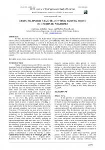
Then, the image has to be brought to life. The javascript XMLHttpRequest() function was used to create request to the web server. The data availability is checked by means of code that catches XMLHttpRequest() exception. We were requesting only one current sample available from the scope. After we got the data, one function parses the data by signals and appended them to the given polyline element: It is to note that numerical data (received from computation or simulation in Matlab) have to be recalculated to the virtual area that is set by attribute viewBox mentioned above. Finally, still one transformation has to be accomplished. It is connected with the fact that originally the origin of the coordinate system is in the left top corner of the drawing area. Therefore it has to be moved near to the left bottom corner and the whole graphical dependence has to be flipped vertically as is shown in Fig. 7. However, both transformations can be realized in m-file immediately after the computation/simulation data are requested, or recalculated by Javascript function in moment of appending the data to the polyline points attribute.
SVG For interactive visualisation of results it is necessary to choose a suitable graphical data format. It has to be standardized and supported by web browsers. We decided to use very promising SVG format because it is a vector format and thanks to its XML structure it can be easily modified, zoomed, animated, etc. We decided to create the dynamic SVG figure that is able to plot data requested from the web server. This option allows us downloading current data from the server dynamically and it gives possibility to enhance velocity, flexibility and
Fig. 7: Polyline coordinate transformation
Communication diagram As it is shown in Fig.8 the client side of the application communicates with server only via http requests. All asynchronous operations are realized using XmlHttpRequest method that communicates with Apache web server on the server side. The Apache server processes the request and forwards it to the mod_python which accomplishes all necessary logic. Then Python calls Matlab via the COM interface. It is to say that in this way (via Matlab COM interface) Python is able to access the whole Matlab environment together with Simulink or RTW. The direct action for the magnetic levitation plant is provided using I/O PC card which is accessible from Simulink over the RTW.
(JPD 3 2005/NP1-047, No. 13120200115). This support is very gratefully acknowledged.
REFERENCES [1]
[2]
[3]
[4]
[5]
[6] Fig. 8: Communication diagram
CONCLUSION The presented approach of the remote control combines several technologies that can be used all together. It was shown how to exploit Matlab capabilities via COM object and the Python realisation and that the asynchronous interactivity can be provided over Internet with a simple web browser that can be used as a client without any special software. The advantage of this solution consists in the fact that the presented implementation, with small customization, may serve as a basic framework for remote control and online graphical visualization of any experiment.
[7] [8] [9] [10] [11] [12] [13] [14] [15]
P. Karagiannis, I. Markelis, K. Paparrizos, N. Samaras, A.Sifaleras, "E-learning technologies: employing Matlab web server to facilitate the education of mathematical programming", Int. J. of Math. Education in Science and Technology, Vol. 37, No. 7/15 Oct. 2006. J. Liguš, J. Ligušová, I. Zolotová, "Distributed Remote Laboratories in Automation Education," 16th EAEEIE Annual Conf. on Innovation in Education for Electr. and Information Eng., Lappeenranta, Finland, June 2005. F. Michau, S. Gentil, M. Barrault, "Expected benefits of web-based learning for engineering education: examples in control engineering", European Journal of Engineering Education, Vol. 26, No. 2/June 1, 2001. S. Müller, H. Waller, "Efficient Integration Of RealTime Hardware And Web Based Services Into MATLAB", 11th European Simulation Symposium, October 1999, Erlangen, Germany. F. Schauer, M. Ožvoldová, F. Lustig, “Remote Scientific Experiments across Internet - the Technology for Reinforcing Partnership inEducation”, REV Conference 2008, Duesseldorf, Germany, 2008. Chr. Schmid, „Internet - basiertes Lernen“, Automatisierungstechnik, 51, No. 11, pp. 485-493, 2003. M. Šimunek, P. Bisták, M. Huba, “Virtual Laboratory for Control of Real Systems”, Int. Conference ICETA, September, Košice, Slovakia, 2005. K. Žáková, M. Sedlák, “Remote Control of Experiments via Matlab”, International Journal of Online Engineering (iJOE), Vol. 2, No. 3, 2006. K. Žáková, M. Sedlák, “Remote Experiments in Matlab”, European Control Conference ECC '07, Kos, Greece, 2007 http://www.humusoft.cz/models/ce152.htm http://www.mathworks.com http://www.w3.org/Graphics/SVG/9 http://www.adobe.com/svg/ http://www.fauskes.net/nb/parsing-simulink/ http://pyparsing.wikispaces.com
THE AUTHORS From the other point of view this article can be understood as a contribution to realisation of remote labs that are essential part of e-learning activities in control engineering.
ACKNOWLEDGMENT This work was supported in part by the Slovak Grant Agency, Grant No. VEGA 1/3089/06 and by the ESF projects “Preparation of university teachers for ICT in education” (SOP ĽZ-2005/NP1-022, No. 11230220525, JPD BA Cieľ 3-2005/NP1-018, No. 13120120287) and “PhD students for Modern Industrial Automation in SR”
Ing. Michal Sedlák is PhD. student at the Faculty of Electrical Engineering and Information Technology, Slovak University of Technology in Bratislava. He is dealing with technologies for virtual and remote laboratories. Ing. Katarína Žáková, PhD. graduated from the Slovak University of Technology in Technical Cybernetics in 1991. Since 1991 she is with the Faculty of Electrical Engineering and Information Technology, Slovak University of Technology in Bratislava. Her current research activities are connected with computer aided control design; Internet based interactive education and e-learning.