Printing History: November 2000 New for MATLAB 6.0 (Release12) (Online only)
.... 4-7. Managing GUI Data with the Handles Structure . . . . . . . . 4-10. Passing ...
MATLAB ®
The Language of Technical Computing
Computation Visualization Programming
Creating Graphical User Interfaces Version 1
How to Contact The MathWorks: www.mathworks.com comp.soft-sys.matlab
Web Newsgroup
[email protected]
Technical support Product enhancement suggestions Bug reports Documentation error reports Order status, license renewals, passcodes Sales, pricing, and general information
508-647-7000
Phone
508-647-7001
Fax
The MathWorks, Inc. 3 Apple Hill Drive Natick, MA 01760-2098
Mail
[email protected] [email protected] [email protected] [email protected] [email protected]
For contact information about worldwide offices, see the MathWorks Web site. Creating Graphical User Interfaces COPYRIGHT 2000 by The MathWorks, Inc. The software described in this document is furnished under a license agreement. The software may be used or copied only under the terms of the license agreement. No part of this manual may be photocopied or reproduced in any form without prior written consent from The MathWorks, Inc. FEDERAL ACQUISITION: This provision applies to all acquisitions of the Program and Documentation by or for the federal government of the United States. By accepting delivery of the Program, the government hereby agrees that this software qualifies as "commercial" computer software within the meaning of FAR Part 12.212, DFARS Part 227.7202-1, DFARS Part 227.7202-3, DFARS Part 252.227-7013, and DFARS Part 252.227-7014. The terms and conditions of The MathWorks, Inc. Software License Agreement shall pertain to the government’s use and disclosure of the Program and Documentation, and shall supersede any conflicting contractual terms or conditions. If this license fails to meet the government’s minimum needs or is inconsistent in any respect with federal procurement law, the government agrees to return the Program and Documentation, unused, to MathWorks. MATLAB, Simulink, Stateflow, Handle Graphics, and Real-Time Workshop are registered trademarks, and Target Language Compiler is a trademark of The MathWorks, Inc. Other product or brand names are trademarks or registered trademarks of their respective holders.
Printing History: November 2000 New for MATLAB 6.0 (Release12) (Online only) June 2001 Revised for MATLAB 6.1(Release 12.1 (Online only)
Contents Getting Started with GUIDE
1 GUIDE – GUI Development Environment . . . . . . . . . . . . . . . 1-3 GUIDE Toolset . . . . . . . . . . . . . . . . . . . . . . . . . . . . . . . . . . . . . . 1-4 Understanding How to Create GUIs . . . . . . . . . . . . . . . . . . . . . 1-4 Getting Started Example . . . . . . . . . . . . . . . . . . . . . . . . . . . . . . 1-5 Example – The GUI Design . . . . . . . . . . . . . . . . . . . . . . . . . . . . 1-5 Example – Laying Out the GUI . . . . . . . . . . . . . . . . . . . . . . . . . 1-6 Creating the Layout . . . . . . . . . . . . . . . . . . . . . . . . . . . . . . . . . . 1-7 Example – Programming the GUI . . . . . . . . . . . . . . . . . . . . . . 1-16 Example – Testing the GUI . . . . . . . . . . . . . . . . . . . . . . . . . . . 1-19 Example – Adding the File Menu to the GUI . . . . . . . . . . . . . 1-20 Example – Programming the Menu Callbacks . . . . . . . . . . . . 1-24 User Interface Controls . . . . . . . . . . . . . . . . . . . . . . . . . . . . . . Push Buttons . . . . . . . . . . . . . . . . . . . . . . . . . . . . . . . . . . . . . . . Toggle Buttons . . . . . . . . . . . . . . . . . . . . . . . . . . . . . . . . . . . . . . Radio Buttons . . . . . . . . . . . . . . . . . . . . . . . . . . . . . . . . . . . . . . Checkboxes . . . . . . . . . . . . . . . . . . . . . . . . . . . . . . . . . . . . . . . . Edit Text . . . . . . . . . . . . . . . . . . . . . . . . . . . . . . . . . . . . . . . . . . Static Text . . . . . . . . . . . . . . . . . . . . . . . . . . . . . . . . . . . . . . . . . Sliders . . . . . . . . . . . . . . . . . . . . . . . . . . . . . . . . . . . . . . . . . . . . Frames . . . . . . . . . . . . . . . . . . . . . . . . . . . . . . . . . . . . . . . . . . . List Boxes . . . . . . . . . . . . . . . . . . . . . . . . . . . . . . . . . . . . . . . . . Popup Menus . . . . . . . . . . . . . . . . . . . . . . . . . . . . . . . . . . . . . . Enabling or Disabling Controls . . . . . . . . . . . . . . . . . . . . . . . . Axes . . . . . . . . . . . . . . . . . . . . . . . . . . . . . . . . . . . . . . . . . . . . . . Figure . . . . . . . . . . . . . . . . . . . . . . . . . . . . . . . . . . . . . . . . . . . . .
1-26 1-26 1-27 1-27 1-29 1-29 1-30 1-30 1-32 1-33 1-34 1-35 1-36 1-37
i
MATLAB GUIs
2 Introduction . . . . . . . . . . . . . . . . . . . . . . . . . . . . . . . . . . . . . . . . . . 2-2 Creating GUIs with GUIDE . . . . . . . . . . . . . . . . . . . . . . . . . . . . 2-3 GUI Development Environment . . . . . . . . . . . . . . . . . . . . . . . . . 2-3 Editing Version 5 GUIs with Version 6 GUIDE . . . . . . . . . . . 2-6 Selecting GUIDE Application Options . . . . . . . . . . . . . . . . . . . 2-8 Configuring the Application M-File . . . . . . . . . . . . . . . . . . . . . . 2-8 Resize Behavior . . . . . . . . . . . . . . . . . . . . . . . . . . . . . . . . . . . . . . Making Your GUI Nonresizable . . . . . . . . . . . . . . . . . . . . . . . . Allowing Proportional GUI Resizing . . . . . . . . . . . . . . . . . . . . . User-Specified Resize Operation . . . . . . . . . . . . . . . . . . . . . . . .
2-10 2-10 2-10 2-11
Command-Line Accessibility . . . . . . . . . . . . . . . . . . . . . . . . . . Access Options . . . . . . . . . . . . . . . . . . . . . . . . . . . . . . . . . . . . . . Figure Properties That Control Access . . . . . . . . . . . . . . . . . . . Using findobj . . . . . . . . . . . . . . . . . . . . . . . . . . . . . . . . . . . . . . .
2-12 2-12 2-12 2-13
Electing to Generate Only the FIG-File . . . . . . . . . . . . . . . . . 2-14 The Generated M-File . . . . . . . . . . . . . . . . . . . . . . . . . . . . . . . . Callback Function Names and Arguments . . . . . . . . . . . . . . . . Application Allows Only One Instance to Run . . . . . . . . . . . . . Using the System Background Colors . . . . . . . . . . . . . . . . . . . Waiting for User Input . . . . . . . . . . . . . . . . . . . . . . . . . . . . . . .
2-15 2-15 2-18 2-18 2-20
Renaming Application Files and Tags . . . . . . . . . . . . . . . . . . Using Save As . . . . . . . . . . . . . . . . . . . . . . . . . . . . . . . . . . . . . . Getting Everything Right . . . . . . . . . . . . . . . . . . . . . . . . . . . . . Changing Component Tag Properties . . . . . . . . . . . . . . . . . . . . Changing the Name of Callback Subfunctions . . . . . . . . . . . . . Changing the Name of the M-File and FIG-File . . . . . . . . . . .
2-21 2-21 2-21 2-21 2-22 2-24
ii
GUIDE Layout Tools
3 GUI Layout Tools . . . . . . . . . . . . . . . . . . . . . . . . . . . . . . . . . . . . . 3-2 Laying Out GUIs – The Layout Editor . . . . . . . . . . . . . . . . . . . Placing an Object In the Layout Area . . . . . . . . . . . . . . . . . . . . . Activating the Figure . . . . . . . . . . . . . . . . . . . . . . . . . . . . . . . . . . Saving the Layout . . . . . . . . . . . . . . . . . . . . . . . . . . . . . . . . . . . . Displaying Your GUI . . . . . . . . . . . . . . . . . . . . . . . . . . . . . . . . . . Layout Editor Preferences . . . . . . . . . . . . . . . . . . . . . . . . . . . . . . Layout Editor Context Menus . . . . . . . . . . . . . . . . . . . . . . . . . . .
3-4 3-4 3-5 3-6 3-6 3-6 3-7
Aligning Components in the Layout Editor . . . . . . . . . . . . . Aligning Groups of Components – The Alignment Tool . . . . . Grids and Rulers . . . . . . . . . . . . . . . . . . . . . . . . . . . . . . . . . . . . Aligning Components to Guide Lines . . . . . . . . . . . . . . . . . . . . Front to Back Positioning . . . . . . . . . . . . . . . . . . . . . . . . . . . . .
3-10 3-10 3-12 3-13 3-14
Setting Component Properties – The Property Inspector
3-16
Viewing the Object Hierarchy – The Object Browser . . . . 3-18 Creating Menus – The Menu Editor . . . . . . . . . . . . . . . . . . . . Defining Menus for the Menubar . . . . . . . . . . . . . . . . . . . . . . . Menu Callbacks . . . . . . . . . . . . . . . . . . . . . . . . . . . . . . . . . . . . . Defining Context Menus . . . . . . . . . . . . . . . . . . . . . . . . . . . . . .
3-19 3-19 3-24 3-25
Saving the GUI . . . . . . . . . . . . . . . . . . . . . . . . . . . . . . . . . . . . . . 3-29 FIG-Files . . . . . . . . . . . . . . . . . . . . . . . . . . . . . . . . . . . . . . . . . . . 3-29
Programming GUIs
4 GUI Programming Topics . . . . . . . . . . . . . . . . . . . . . . . . . . . . . . 4-2 Understanding the Application M-File . . . . . . . . . . . . . . . . . . 4-3
iii
Execution Paths in the Application M-File . . . . . . . . . . . . . . . . 4-4 Initializing the GUI . . . . . . . . . . . . . . . . . . . . . . . . . . . . . . . . . . . 4-7 Managing GUI Data with the Handles Structure . . . . . . . . Passing Data in the Handles Structure . . . . . . . . . . . . . . . . . . Obtaining the Updated Handles Structure . . . . . . . . . . . . . . . If You Are Not Using a Handles Structure . . . . . . . . . . . . . . . . Application-Defined Data . . . . . . . . . . . . . . . . . . . . . . . . . . . . .
4-10 4-10 4-12 4-12 4-14
Designing for Cross-Platform Compatibility . . . . . . . . . . . . Using the Default System Font . . . . . . . . . . . . . . . . . . . . . . . . . Using Standard Background Color . . . . . . . . . . . . . . . . . . . . . . Cross-Platform Compatible Figure Units . . . . . . . . . . . . . . . . .
4-15 4-15 4-16 4-17
Types of Callbacks . . . . . . . . . . . . . . . . . . . . . . . . . . . . . . . . . . . Callback Properties for All Graphics Objects . . . . . . . . . . . . . . Callback Properties for Figures . . . . . . . . . . . . . . . . . . . . . . . . Which Callback Executes . . . . . . . . . . . . . . . . . . . . . . . . . . . . . Adding A Callback . . . . . . . . . . . . . . . . . . . . . . . . . . . . . . . . . . .
4-18 4-18 4-18 4-19 4-19
Interrupting Executing Callbacks . . . . . . . . . . . . . . . . . . . . . Controlling Interruptibility . . . . . . . . . . . . . . . . . . . . . . . . . . . . The Event Queue . . . . . . . . . . . . . . . . . . . . . . . . . . . . . . . . . . . . Event Processing During Callback Execution . . . . . . . . . . . . .
4-20 4-20 4-20 4-21
Controlling GUI Figure Window Behavior . . . . . . . . . . . . . . 4-23 Using Modal Figure Windows . . . . . . . . . . . . . . . . . . . . . . . . . . 4-23
Application Examples
5 Examples of Application Techniques . . . . . . . . . . . . . . . . . . . . 5-2 GUI with Multiple Axes . . . . . . . . . . . . . . . . . . . . . . . . . . . . . . . . Techniques Used in the Example . . . . . . . . . . . . . . . . . . . . . . . . View the Layout and Application M-File . . . . . . . . . . . . . . . . . . Design of the GUI . . . . . . . . . . . . . . . . . . . . . . . . . . . . . . . . . . . .
5-3 5-3 5-4 5-4
iv
Plot Push Button Callback . . . . . . . . . . . . . . . . . . . . . . . . . . . . . 5-7 Launching a Dialog to Confirm an Operation . . . . . . . . . . . . 5-9 Dialog Requirements . . . . . . . . . . . . . . . . . . . . . . . . . . . . . . . . . . 5-9 View the Layout and Application M-File . . . . . . . . . . . . . . . . . 5-10 Implementing the GUI . . . . . . . . . . . . . . . . . . . . . . . . . . . . . . . 5-10 The Close Button Callback . . . . . . . . . . . . . . . . . . . . . . . . . . . . 5-12 The Confirmation Dialog M-file . . . . . . . . . . . . . . . . . . . . . . . . 5-12 Launch the Dialog . . . . . . . . . . . . . . . . . . . . . . . . . . . . . . . . . . . 5-13 Specify the Location of the Dialog . . . . . . . . . . . . . . . . . . . . . . . 5-14 Wait for User Response . . . . . . . . . . . . . . . . . . . . . . . . . . . . . . . 5-14 Executing a Callback . . . . . . . . . . . . . . . . . . . . . . . . . . . . . . . . . 5-15 Defining the Yes and No Buttons Callbacks . . . . . . . . . . . . . . 5-15 Protecting the GUI with a Close Request Function . . . . . . . . . 5-16 List Box Directory Reader . . . . . . . . . . . . . . . . . . . . . . . . . . . . View the Layout and Application M-File . . . . . . . . . . . . . . . . . Implementing the GUI . . . . . . . . . . . . . . . . . . . . . . . . . . . . . . . Specifying the Directory to List . . . . . . . . . . . . . . . . . . . . . . . . . Loading the List Box . . . . . . . . . . . . . . . . . . . . . . . . . . . . . . . . . The List Box Callback . . . . . . . . . . . . . . . . . . . . . . . . . . . . . . . .
5-18 5-18 5-19 5-19 5-21 5-22
Accessing Workspace Variables from a List Box . . . . . . . . . Techniques Used in This Example . . . . . . . . . . . . . . . . . . . . . . View the Layout and Application M-File . . . . . . . . . . . . . . . . . Reading Workspace Variables . . . . . . . . . . . . . . . . . . . . . . . . . . Reading the Selections from the List Box . . . . . . . . . . . . . . . . .
5-24 5-24 5-25 5-25 5-26
A GUI to Set Simulink Model Parameters . . . . . . . . . . . . . . Techniques Used in This Example . . . . . . . . . . . . . . . . . . . . . . View the Layout and Application M-File . . . . . . . . . . . . . . . . . How to Use the GUI (Text of GUI Help) . . . . . . . . . . . . . . . . . . Launching the GUI . . . . . . . . . . . . . . . . . . . . . . . . . . . . . . . . . . Programming the Slider and Edit Text Components . . . . . . . . Running the Simulation from the GUI . . . . . . . . . . . . . . . . . . . Removing Results from the List Box . . . . . . . . . . . . . . . . . . . . Plotting the Results Data . . . . . . . . . . . . . . . . . . . . . . . . . . . . . The GUI Help Button . . . . . . . . . . . . . . . . . . . . . . . . . . . . . . . . Closing the GUI . . . . . . . . . . . . . . . . . . . . . . . . . . . . . . . . . . . . . The List Box Callback . . . . . . . . . . . . . . . . . . . . . . . . . . . . . . . .
5-28 5-28 5-28 5-29 5-30 5-31 5-33 5-34 5-35 5-37 5-38 5-38
v
An Address Book Reader . . . . . . . . . . . . . . . . . . . . . . . . . . . . . Techniques Used in This Example . . . . . . . . . . . . . . . . . . . . . . Managing Global Data . . . . . . . . . . . . . . . . . . . . . . . . . . . . . . . . View the Layout and Application M-File . . . . . . . . . . . . . . . . . Launching the GUI . . . . . . . . . . . . . . . . . . . . . . . . . . . . . . . . . . Loading an Address Book Into the Reader . . . . . . . . . . . . . . . . The Contact Name Callback . . . . . . . . . . . . . . . . . . . . . . . . . . . The Contact Phone # Callback . . . . . . . . . . . . . . . . . . . . . . . . . Paging Through the Address Book – Prev/Next . . . . . . . . . . . . Saving Changes to the Address Book from the Menu . . . . . . . The Create New Menu . . . . . . . . . . . . . . . . . . . . . . . . . . . . . . . . The Address Book Resize Function . . . . . . . . . . . . . . . . . . . . . .
vi
Contents
5-40 5-40 5-40 5-41 5-41 5-43 5-45 5-47 5-48 5-50 5-51 5-52
1 Getting Started with GUIDE GUIDE – GUI Development Environment . . . . . . . 1-3 GUIDE Toolset . . . . . . . . . . . . . . . . . . . 1-4 Understanding How to Create GUIs . . . . . . . . . . . 1-4 Getting Started Example . . . . . . . Example – The GUI Design . . . . . . . Example – Laying Out the GUI . . . . . . Creating the Layout . . . . . . . . . . Example – Programming the GUI . . . . . Example – Testing the GUI . . . . . . . Example – Adding the File Menu to the GUI Example – Programming the Menu Callbacks
. . . . . . . .
. . . . . . . .
. . . . . . . .
. . . . . . . .
. . . . . . . .
. . . . . . . .
. . . . . . . .
User Interface Controls . . Push Buttons . . . . . . . Toggle Buttons . . . . . . Radio Buttons . . . . . . . Checkboxes . . . . . . . . Edit Text . . . . . . . . . Static Text . . . . . . . . Sliders . . . . . . . . . . Frames . . . . . . . . . List Boxes . . . . . . . . Popup Menus . . . . . . . Enabling or Disabling Controls Axes . . . . . . . . . . .
. . . . . . . . . . . . .
. . . . . . . . . . . . .
. . . . . . . . . . . . .
. . . . . . . . . . . . .
. . . . . . . . . . . . .
. . . . . . . . . . . . .
. 1-26 . 1-26 . 1-27 . 1-27 . 1-29 . 1-29 . 1-30 . 1-30 . 1-32 . 1-33 . 1-34 . 1-35 . 1-36
. . . . . . . . . . . . .
. . . . . . . . . . . . .
. . . . . . . . . . . . .
. . . . . . . . . . . . .
. . . . . . . . . . . . .
. . . . . . . . . . . . .
1-5 1-5 1-6 1-7 1-16 1-19 1-20 1-24
Figure . . . . . . . . . . . . . . . . . . . . . . 1-37
1
Getting Started with GUIDE
This section illustrates the process of using GUIDE to create GUIs: • GUI Development Environment – overview of the layout tools provided by GUIDE. • Getting Started Example – an example illustrating how to use GUIDE. • User Interface Controls – descriptions of the components you use to create GUIs. For more in depth information about creating graphical users interfaces see MATLAB GUIs.
1-2
GUIDE – GUI Development Environment
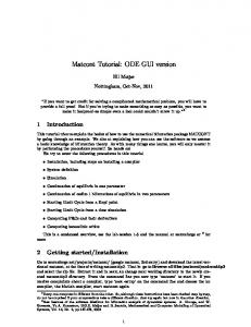
GUIDE – GUI Development Environment GUIDE, MATLAB’s Graphical User Interface development environment, provides a set of tools for laying out your GUI. The Layout Editor is the control panel for GUIDE. To start the Layout Editor, use the guide command. The following picture shows the Layout Editor with the Show names in component palette preference selected.
Alignment Tool
Menu Editor
Property Inspector Object Browser
Figure Activator
Undo
Redo
Layout Area Component Palette
Figure Resize Tab
1-3
1
Getting Started with GUIDE
GUIDE Toolset The following links provide more information on the full set of GUIDE development tools. • Layout Editor – add and arrange objects in the figure window. • Alignment Tool – align objects with respect to each other. • Property Inspector – inspect and set property values. • Object Browser – observe a hierarchical list of the Handle Graphics objects in the current MATLAB session. • Menu Editor – create menus for the window menu bar and context menus for any component in your layout.
Understanding How to Create GUIs For more in depth information on how GUIDE works, see Creating GUIs with GUIDE. For a simple example to get started using GUIDE see the next section, A GUI Example.
1-4
Getting Started Example
Getting Started Example This example shows how to create a GUI using GUIDE. It illustrates the process you should follow when creating your GUI. This process entails: • Design the GUI – often it is better to design the GUI on paper before beginning the implementation process. • Laying out the GUI figure – the GUI figure is the window that contains the user interface controls, such as push buttons and menus and can also contain axes for displaying graphs and images. • Program the GUI – the M-file generated by GUIDE displays and controls the GUI figure you created with GUIDE. It is in this M-file that you program the callback functions for each user interface control. GUIDE’s layout tools enable you to add and arrange components in the GUI figure. When you activate or save your GUI for the first time, GUIDE generates the M-file you use to program the GUI. This example is presented in five sections: • Designing the GUI – a description of the GUI design • Laying out the GUI – placing the controls within the Layout Editor • Programming the GUI – writing the callbacks for the controls • Laying out the menu – adding the menu to the GUI figure • Programming the menu callbacks – writing the callbacks for the menus
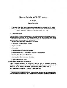
Example – The GUI Design The GUI used in this example contains one axes that can display either a surface, mesh, or contour plot of data selected from the popup menu. The File menu provides options to print the graphic and to close the GUI. The following picture shows a sketch similar to what you might use as a starting point for the design.
1-5
1
Getting Started with GUIDE
File menu with Print and Close
)LOH
Surf Axes
Mesh
Push buttons to select plot type
Contour Select Data peaks
Popup for selecting data
The popup menu contains three strings – “peaks”, “membrane”, and “sinc”, which enable the user to select the data to plot. The GUI program generates this data by executing one of three functions.
Example – Laying Out the GUI This section illustrates how to layout GUI components (i.e., user interface controls, like push buttons, popup menus, text labels, etc.) in the GUI.
Layout and Code for the Example Use the following links to display the GUIDE Layout Editor and the MATLAB Editor with a completed version of this example. This enables you to see the values of all component properties and to understand how the components are assembled to create the GUI. You can also see a complete listing of the code that is discussed in the following sections.
1-6
Getting Started Example
Note The following links execute MATLAB commands and are designed to work within the MATLAB Help browser. The first link adds a directory to your MATLAB path.
Layout Editor with completed GUI layout MATLAB Editor with completed application M-file
View an Animated Demo The following link displays an animated version of this example. Show GUIDE demonstration
Creating the Layout Open the Layout Editor using the guide command. This displays a blank layout grid to which you can added components that you select from the palette.
1. Set the GUI Figure Size Specify the size of the GUI by resizing the grid area in the Layout Editor. Click on the lower-right corner and resize the grid until it is about 4-by-3 inches.
1-7
1
Getting Started with GUIDE
If you want to set the size of the GUI to an exact value, set the Position property using the Property Inspector (select Property Inspector from the View menu). Change the Units to inches to set the figure size, then change them back to characters before deploying the GUI.
1-8
Getting Started Example
2. Add the Components Select the components to add from the palette and drag them into the layout area. You can resize components from any corner handle while it is selected. Add three push buttons, a static text, a popup menu, and an axes. Arrange them as shown in the following picture.
1-9
1
Getting Started with GUIDE
3. Align the Objects To align components with respect to one another, select Align Objects from the Tools menu. The Alignment Tool sets the relative vertical and horizontal alignment of selected components. The following picture show the three push buttons selected (ctrl+click to multiple select) and ready to be aligned according to the settings: • 20 pixels spacing between push buttons in the vertical direction. • Left-aligned in the horizontal direction.
1-10
Getting Started Example
4. Set Properties for Each Component To set the properties of each component, select the Property Inspector from the View menu.
Push Buttons and Static Text Set the String properties of the push buttons and static text to create the labels. For example, the following picture shows the Surf push button properties.
1-11
1
Getting Started with GUIDE
Popup Menu Items Each item in the popup menu list needs to be on a separate line in the String property edit box:
1-12
Getting Started Example
Tag and Callback Properties When you first add a component to the layout, its Callback property is set to the string .
1-13
1
Getting Started with GUIDE
When you save or activate the GUI, GUIDE converts this string to one that calls the callback subfunction in the generated M-file. GUIDE uses the component’s Tag property to name its callback function. It is, therefore, useful to set Tag properties to descriptive names before you save or activate the GUI for the first time.
1-14
Getting Started Example
This example sets the popup menu Tag to data_popup, resulting in the name data_popup_Callback for the popup menu’s callback function. Set the push button Tags to surf_pushbutton, mesh_pushbutton, and contour_pushbutton. The next section, Example – Programming the GUI, provides more information on the callback functions for this GUI.
1-15
1
Getting Started with GUIDE
5. Activate the GUI Activate the GUI by selecting Activate Figure from the Tools menu or use the activator button from the GUIDE toolbar. The following picture shows the GUI. See Activating the Figure for more detailed information on what figure activation does.
The Application M-File Activating the GUI also opens the MATLAB editor with the M-file generated for the GUI. You must program the various components in your GUI in this M-file. The next section show how to do this.
Note The name of the FIG-file saved by the Layout Editor and the generated application M-file must match. See Renaming Application Files and Tags if you want to rename files or change Tags after first activating the GUI.
Example – Programming the GUI When you first save or activate the GUI, GUIDE generates the application M-file that will contain all the code to launch and control the GUI. You must
1-16
Getting Started Example
write the callbacks – the functions that execute when users activate a component in the GUI. The application M-file: • Initializes and launches the GUI. • Contains the callback functions for all components in the GUI. GUIDE generates this M-file with empty subfunctions for each component that has a callback associated with it – in this example, the three push buttons and the popup menu have callbacks.
A Note About Handles and Global Data A key feature in the generated M-file is the handles structure. This structure has two purposes. It: • Stores the handles of all controls, menus, and axes used in the GUI. • Stores global data used in the program. Accessing Handles. Each object handle is stored in a field of the handles structure having the same name as the object’s Tag. For example, handles.data_popup
contains the handle of the popup menu used in this example. Storing Global Data. You can store data and pass it to any callback using the handles structure. To do this, create a new field in the handles structure and save it using the guidata function. For example, from the callback of the object whose handle is h, handles.x_data = X; guidata(h,handles)
saves the variable X in the x_data field of the handles structure. guidata then writes the new version of handles to the figure’s application data to save it. To obtain X in another callback, reference the correct field: X = handles.x_data;
For more detailed information on the handles structure, see: • Creating and Storing the Handles Structure
1-17
1
Getting Started with GUIDE
• Managing GUI Data
Popup Menu Callback The popup menu enables users to select the data to plot. For simplicity, this example uses MATLAB functions to generate the data, but a more typical scenario would involve reading data from a file. This callback reads the popup menu Value property to determine what item is currently displayed and loads data into the handles structure accordingly. function varargout = data_popup_Callback(h,eventdata,handles,varargin) val = get(h,'Value'); switch val case 1 % User selected peaks handles.data = peaks(35); case 2 % User selected membrane handles.data = membrane; case 3 % User selected sinc [x,y] = meshgrid(-8:.5:8); r = sqrt(x.^2+y.^2) + eps; z = sin(r)./r; handles.data = z; end guidata(h,handles) % Save the handles structure after adding data
See Managing GUI Data with the Handles Structure for more information on using the handles structure to pass data between callback functions.
Initializing the Data The callback for the popup menu executes only when users change the currently displayed value. Until this callback runs, there is no data field in the handles structure and no data to plot. This means you must initialize the handles structure by calling the popup menu callback in the initialization section of the application M-file. Add the call to data_popup_Callback after the application M-file initializes the handles structure. See Understanding the Application M-File for information on where in the application M-file to put you initialization code. % Call the popup menu callback to initialize the handles.data % field with the current value of the popup
1-18
Getting Started Example
data_popup_Callback(handles.data_popup,[],handles)
Push Button Callbacks Each of the push buttons creates a different type of plot using the data specified by the current selection in the popup menu. Their callbacks get data from the handles structure and then plot it. Surf push button callback: function varargout = surf_pushbutton_Callback(h,eventdata,handles,varargin) z = handles.data; % Load data from handles structure surf(z);
Mesh push button callback: function varargout = mesh_pushbutton_Callback(h,eventdata,handles,varargin) z = handles.data; % Load data from handles structure mesh(z)
Contour push button callback: function varargout = contour_pushbutton_Callback(h,eventdata,handles,varargin) z = handles.data; % Load data from handles structure contour(z)
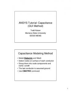
Example – Testing the GUI After writing the callbacks, you can activate the GUI to test it. Activate the GUI by selecting Activate Figure from the Tools menu or use the activator button from the GUIDE toolbar. Select membrane in the popup menu and press the Contour push button. The GUI should look like this:
1-19
1
Getting Started with GUIDE
Example – Adding the File Menu to the GUI The GUI has a File menu with two menu items: • Print – sends the plot to the user’s default printer. This item is grayed out if there is no plot currently displayed. • Close – closes the GUI window. To create the menu, display the Menu Editor by selecting the Menu Editor item in the Tool menu.
1. Add the File Menu Use the New Menu tool to add the top-level menu.
1-20
Getting Started Example
2. Set the Label and Tag Set the Label property to the word File. This is the name of the menu as it appears on the GUI menu bar. Set the Tag property to a descriptive name. GUIDE uses the Tag property to name the menu callback function (as well as the field in the handles structure that contains the menu handle). Initially, the Callback property is set to . This means GUIDE automatically adds a callback function to the application M-file when you save or activate the GUI.
1-21
1
Getting Started with GUIDE
3. Add the Items Select File and click the New Menu Item tool. Each time you click New Menu Item, the editor adds a new submenu to the selected menu.
4. Set the Labels and Tags for the Menu Items Set the Label and Tag properties for each menu item. GUIDE generates a callback for each menu item as well. Save or activate the GUI to add the menu to the menu bar and to add the callbacks to the application M-file. The next section shows you how to program the menu.
1-22
Getting Started Example
5. Activate the GUI After creating the menus with the Menu Editor, you can activate the GUI from the Layout Editor. This causes GUIDE to generate the empty callback functions in the application M-file, which you can now program. Select sinc in the popup menu and click on the Mesh push button. The activated GUI looks like this when you pull down the File menu.
1-23
1
Getting Started with GUIDE
Example – Programming the Menu Callbacks After adding the File menu to the layout (you cannot see the menu bar in the Layout Editor), edit the application M-file. It will contain empty callback functions for the File menu as well as the Print and Close items.
File Menu Callback By default, when a user clicks on the File menu, MATLAB displays the menu items. Therefore, the only purpose of the File menu callback in this example is to disable the Print menu item when there is no plot being displayed. You can accomplish this by checking to see if the axes Children property is empty (in which case, there is nothing displayed in the axes). The menu’s Enable property controls whether a particular item is active or inactive. The item is grayed out if Enable is set to off. The callback uses isempty to determine if the axes contains a plot and enables or disables the menu accordingly. function varargout = file_menu_Callback(h, eventdata, handles, varargin) if isempty(get(handles.axes1,'Children')) set(handles.print_submenu,'Enable','off')
1-24
Getting Started Example
else set(handles.print_submenu,'Enable','on') end
The Print Item Callback The callback for the Print menu item uses the print command to print the current plot on the user’s default printer. The -f option specifies the GUI figure. Since the figure’s Tag property is set to figure1, the figure’s handle is contained in the figure1 field of the handles structure. function varargout = print_submenu_Callback(h, eventdata, handles, varargin) print -f handles.figure1
The Close Item Callback The callback for the Close menu item uses the delete command to close the GUI figure. Since the figure’s Tag property is set to figure1, the figure’s handle is contained in the figure1 field of the handles structure. function varargout = close_submenu_Callback(h, eventdata, handles, varargin) delete(handles.figure1)
1-25
1
Getting Started with GUIDE
User Interface Controls The Layout Editor component palette contains the user interface controls that you can use in your GUI. These components are MATLAB uicontrol objects and are programmable via their Callback properties. This section provides information on these components. Push Buttons
Sliders
Toggle Buttons
Frames
Radio Buttons
Listboxes
Checkboxes
Popup Menus
Edit Text
Axes
Static Text
Figures
Push Buttons Push buttons generate an action when pressed (e.g., an OK button may close a dialog box and apply settings). When you click down on a push button, it appears depressed; when you release the mouse, the button’s appearance returns to its nondepressed state; and its callback executes on the button up event.
Properties to Set • String – set this property to the character string you want displayed on the push button. • Tag – GUIDE uses the Tag property to name the callback subfunction in the application M-file. Set Tag to a descriptive name (e.g., close_button) before activating the GUI.
Programming the Callback When the user clicks on the push button, its callback executes. Push buttons do not return a value or maintain a state.
1-26
User Interface Controls
Toggle Buttons Toggle buttons generate an action and indicate a binary state (e.g., on or off). When you click on a toggle button, it appears depressed and remains depressed when you release the mouse button, at which point the callback executes. A subsequent mouse click returns the toggle button to the nondepressed state and again executes its callback.
Programming the Callback The callback routine needs to query the toggle button to determine what state it is in. MATLAB sets the Value property equal to the Max property when the toggle button is depressed (Max is 1 by default) and equal to the Min property when the toggle button is not depressed (Min is 0 by default).
From the GUIDE Application M-File The following code illustrates how to program the callback in the GUIDE application M-file. function varargout = togglebutton1_Callback(h,eventdata,handles,varargin) button_state = get(h,'Value'); if button_state == get(h,'Max') % toggle button is pressed elseif button_state == get(h,'Min') % toggle button is not pressed end
Adding an Image to a Push Button or Toggle Button Assign the CData property an m-by-n-by-3 array of RGB values that define a truecolor image. For example, the array a defines 16-by-128 truecolor image using random values between 0 and 1 (generated by rand). a(:,:,1) = rand(16,128); a(:,:,2) = rand(16,128); a(:,:,3) = rand(16,128); set(h,'CData',a)
Radio Buttons Radio buttons are similar to checkboxes, but are intended to be mutually exclusive within a group of related radio buttons (i.e., only one button is in a
1-27
1
Getting Started with GUIDE
selected state at any given time). To activate a radio button, click the mouse button on the object. The display indicates the state of the button.
Implementing Mutually Exclusive Behavior Radio buttons have two states – selected and not selected. You can query and set the state of a radio button through its Value property: • Value = Max, button is selected. • Value = Min, button is not selected. To make radio buttons mutually exclusive within a group, the callback for each radio button must set the Value property to 0 on all other radio buttons in the group. MATLAB sets the Value property to 1 on the radio button clicked by the user. The following subfunction, when added to the application M-file, can be called by each radio button callback. The argument is an array containing the handles of all other radio buttons in the group that must be deselected. function mutual_exclude(off) set(off,'Value',0)
Obtaining the Radio Button Handles. The handles of the radio buttons are available from the handles structure, which contains the handles of all components in the GUI. This structure is an input argument to all radio button callbacks.
The following code shows the call to mutual_exclude being made from the first radio button’s callback in a group of four radio buttons. function varargout = radiobutton1_Callback(h,eventdata,handles,varargin) off = [handles.radiobutton2,handles.radiobutton3,handles.radiobutton4]; mutual_exclude(off) % Continue with callback
. . . After setting the radio buttons to the appropriate state, the callback can continue with its implementation-specific tasks.
1-28
User Interface Controls
Checkboxes Check boxes generate an action when clicked and indicate their state as checked or not checked. Check boxes are useful when providing the user with a number of independent choices that set a mode (e.g., display a toolbar or generate callback function prototypes). The Value property indicates the state of the check box by taking on the value of the Max or Min property (1 and 0 respectively by default): • Value = Max, box is checked. • Value = Min, box is not checked. You can determine the current state of a check box from within its callback by querying the state of its Value property, as illustrated in the following example: function checkbox1_Callback(h,eventdata,handles,varargin) if (get(h,'Value') == get(h,'Max')) % then checkbox is checked-take approriate action else % checkbox is not checked-take approriate action end
Edit Text Edit text controls are fields that enable users to enter or modify text strings. Use edit text when you want text as input. The String property contains the text entered by the user. To obtain the string typed by the user, get the String property in the callback. function edittext1_Callback(h,eventdata,handles,varargin) user_string = get(h,'string'); % proceed with callback...
Obtaining Numeric Data from an Edit Test Component MATLAB returns the value of the edit text String property as a character string. If you want users to enter numeric values, you must convert the characters to numbers. You can do this using the str2double command, which converts strings to doubles. If the user enters non-numeric characters, str2double returns NaN.
1-29
1
Getting Started with GUIDE
You can use the following code in the edit text callback. It gets the value of the String property and converts it to a double. It then checks if the converted value is NaN, indicating the user entered a non-numeric character (isnan) and displays an error dialog (errordlg). function edittext1_Callback(h,eventdata,handles,varargin) user_entry = str2double(get(h,'string')); if isnan(user_entry) errordlg('You must enter a numeric value','Bad Input','modal') end % proceed with callback...
Triggering Callback Execution On UNIX systems, clicking on the menubar of the figure window causes the edit text callback to execute. However, on Microsoft Windows systems, if an editable text box has focus, clicking on the menubar does not cause the editable text callback routine to execute. This behavior is consistent with the respective platform conventions. Clicking on other components in the GUI execute the callback.
Static Text Static text controls displays lines of text. Static text is typically used to label other controls, provide directions to the user, or indicate values associated with a slider. Users cannot change static text interactively and there is no way to invoke the callback routine associated with it.
Sliders Sliders accept numeric input within a specific range by enabling the user to move a sliding bar. Users move the bar by pressing the mouse button and dragging the slide, by clicking in the trough, or by clicking an arrow. The location of the bar indicates a numeric value.
Slider Orientation You can orient the slider either horizontally or vertically by setting the relative width and height of the Position property: • Horizontal slider – width is greater than height. • Vertical slider – height is greater than width.
1-30
User Interface Controls
For example, these settings create a horizontal slider.
Current Value, Range, and Step Size There are four properties that control the range and step size of the slider: • Value – contains the current value of the slider. • Max – defines the maximum slider value. • Min – defines the minimum slider value. • SliderStep – specifies the size of a slider step with respect to the range. The Value property contains the numeric value of the slider. You can set this property to specify an initial condition and query it in the slider’s callback to obtain the value set by the user. For example, your callback could contain the statement. slider_value = get(handles.slider1,'Value');
The Max and Min properties specify the slider’s range (Max - Min). The SliderStep property controls the amount the slider Value property changes when you click the mouse on the arrow button or on the slider trough. Specify SliderStep as a two-element vector. The default, [0.01 0.10], provides a 1 percent change for clicks on an arrow and a 10 percent change for clicks in the trough. The actual step size is a function of the slider step and the slider range.
1-31
1
Getting Started with GUIDE
Designing a Slider Suppose you want to create a slider with the following behavior: • Slider range = 5 to 8 • Arrow step size = 0.4 • Trough step size = 1 • Initial value = 6.5 From these values you need to determine and set the Max, Min, SliderStep, and Value properties. You can do this by adding the following code to the initialization section of the application M-file (after the creation of the handles structure). slider_step(1) = 0.4/(8-5); slider_step(2) = 1/(8-5); set(handles.slider1,'sliderstep',slider_step,... 'max',8,'min',5,'Value',6.5)
You can also assign the slider properties using the Property Inspector: • SliderStep, X .133 • SliderStep, Y .333 • Max 8 • Min 5 • Value 6.5
Triggering Callback Execution The slider callback is executed when the user releases the mouse button.
Frames Frames are boxes that enclose regions of a figure window. Frames can make a user interface easier to understand by visually grouping related controls. Frames have no callback routines associated with them and only uicontrols can appear within frames (axes cannot).
Placing Components on Top of Frames Frames are opaque. If you add a frame after adding components that you want to be positioned within the frame, you need to bring forward those components.
1-32
User Interface Controls
Use the Bring to Front and Send to Back operations in the Layout menu for this purpose.
List Boxes List boxes display a list of items and enable users to select one or more items. The String property contains the list of strings displayed in the list box. The first item in the list has an index of 1. The Value property contains the index into the list of strings that correspond to the selected item. If the user selects multiple items, then Value is a vector of indices. By default, the first item in the list is highlighted when the list box is first displayed. If you do not want any item highlighted, then set the Value property to empty, []. The ListboxTop property defines which string in the list displays as the top most item when the list box is not large enough to display all list entries. ListboxTop is an index into the array of strings defined by the String property and must have a value between 1 and the number of strings. Noninteger values are fixed to the next lowest integer.
Single or Multiple Selection The values of the Min and Max properties determine whether users can make single or multiple selections: • If Max – Min > 1, then list boxes allow multiple item selection. • If Max – Min 0 varargout{1} = fig; end elseif ischar(varargin{1}) % INVOKE NAMED SUBFUNCTION OR CALLBACK try if (nargout) [varargout{1:nargout}] = feval(varargin{:}); else feval(varargin{:}); % FEVAL switchyard end catch disp(lasterr); end end
Whether you use the GUIDE-generated application M-file or create your own code, the programming techniques discussed here provide useful approaches to GUI programming. The following sections discuss the architecture and functioning of the application M-file:
4-3
4
Programming GUIs
• Execution Paths in the Application M-File • Initializing the GUI • Managing GUI Data with the Handles Structure
Execution Paths in the Application M-File The application M-file follows different execution paths depending on what arguments you use. For example: • Calling the M-file with no arguments launches the GUI (if you assign an output argument, the M-file returns the handle of the GUI figure). • Calling the M-file with the name of a subfunction as the first argument executes that specific subfunction (typically, but not necessarily, a callback routine).
The Switchyard Code The application M-file contains a “switchyard” that enables it to switch to various execution paths depending on how it is called. The switchyard is implemented using the feval function. feval executes the subfunction whose name is passed as a string argument in a call to the application M-file. feval executes within a try/catch statement to catch errors caused by passing the name of nonexistent subfunctions. The following code generated by GUIDE implements the switchyard (you should not modify this code since the functioning of the GUI depends on its correct behavior). if nargin == 0 % If no arguments, open GUI fig = openfig(mfilename,'reuse');
. . . elseif ischar(varargin{1}) % INVOKE NAMED SUBFUNCTION OR CALLBACK try if (nargout) [varargout{1:nargout}] = feval(varargin{:}); else feval(varargin{:}); % FEVAL switchyard end
4-4
Understanding the Application M-File
catch disp(lasterr); end end
Any output arguments returned by your callback subfunction are then returned though the main function via the first feval statement: if (nargout) % If there are output arguments [varargout{1:nargout}] = feval(varargin{:});
In addition, any input arguments you have added to the Callback property string are included in the evaluated statement. See Launching a Dialog to Confirm an Operation for an example that defines additional input arguments. The following diagram illustrates the execution path for the application M-file.
4-5
4
Programming GUIs
Application M-File Execution Path
Call application M-file Single or Multiple Instance Check input arguments
If no arguments launch GUI
Figure exists and is reused
Yes
Raise GUI figure
No
Arguments > 0 and first argument is string
Open figure
GUI Initialization Use system background color
Execute Callback
Build handles struct from Tag properties
feval the variable argument list
• First argument is subfunction name • Pass remaining arguments to subfunction
Wait for user input option
Return output arguments
End of program
4-6
Understanding the Application M-File
Initializing the GUI The application M-file automatically includes some useful techniques for managing the GUI. These technique include: • Open the FIG-file. • Single/multiple instance control. • On screen placement of the GUI figure regardless of target computer screen size and resolution. • Structure containing GUI component handles automatically created. • Automatic naming of Tag property, generation of subfunction prototype, and assignment of Callback property string. • Single M-file contains code to launch GUI and execute callbacks.
Opening the FIG-File The application M-file uses the openfig command to load the GUI figure. The actual command is fig = openfig(mfilename,'reuse');
It is important to note that this statement derives the name of the FIG-file from the application M-file (the mfilename command returns the name of the currently executing M-file). If you are using the application M-file generated by GUIDE, you must keep the names of the FIG-file and M-file the same. The reuse argument specifies that there can be only a single instance of the GUI displayed at any time (see below).
Single vs. Multiple Instance of the GUI One of the decisions you must make when designing GUIs is whether you want to allow multiple instances of the GUI figure to exist at one time. If you choose to allow only a single instance of the GUI, subsequent attempts to create another GUI figure simply bring the existing GUI to the front of other windows. The GUIDE Layout Editor is an example of a GUI that allows multiple instances. This GUI enables users to have a number of layouts open simultaneously.
4-7
4
Programming GUIs
Positioning the GUI Onscreen The application M-file uses the movegui command to ensure the GUI figure is visible on the screen of the target computer, regardless of the screen size and resolution. If the specified figure position would result in the GUI being placed off screen, movegui moves the figure to the nearest on-screen location with respect to the specified position. The statement in the application M-file is movegui(fig,'onscreen')
where fig is the handle of GUI figure returned by the openfig command. movegui also provides options to place the GUI at specific locations on the
screen.
Creating and Storing the Handles Structure When you launch the GUI, the application M-file creates a structure that saves the handles of all the components in the GUI. GUIDE stores this structure in the figure’s application data so that it can be retrieved when needed (e.g., from a callback subfunction). The name of the structure field containing a given object’s handle is taken from the object’s Tag property. For example, an object with a Tag value of pushbutton1 is accessed with handles.pushbutton1
You can access the figure’s hidden handle in a similar way. If the figure’s Tag is figure1, then handles.figure1
contains the figure’s handle. The application M-files uses guihandles and guidata to create and store the structure. handles = guihandles(fig); % Create handle struct guidata(fig,handles); % Save struct in figure’s app data
Note that only those components whose Tag property is set to a string that is a valid variable name are included in this structure. Use isvarname to determine if a string is a valid name.
4-8
Understanding the Application M-File
The handles structure is one of the arguments passed to each callback. You can also use this same structure to save data and pass it between subfunctions. See Managing GUI Data for a discussion of how to use the handles structure for data.
4-9
4
Programming GUIs
Managing GUI Data with the Handles Structure GUIDE provides a mechanism for storing and retrieving global data using the same structure that contains the GUI component handles. The handles structure, which containing the handles of all the components in the GUI, is passed to each callback in the application M-file. Therefore, this structure is useful for saving any global data. The following example illustrates this technique. If you are not familiar with MATLAB structures, see Structures for more information.
Passing Data in the Handles Structure This example demonstrates how to use the handles structure to pass data between callbacks. Suppose you want to create a GUI containing a slider and an editable text box that behaves as follows: • When users moves the slider, the text box displays the slider’s current value. • When users types a value into the text box, the slider updates to this value. • If they enter an out-of-range value in the text box, the application returns a message indicating how many erroneous values have been entered. This picture shows the GUI with a static text field above the edit text box.
4-10
Managing GUI Data with the Handles Structure
Defining the Data Fields During Initialization The following excerpt from the GUI setup code show two additional fields defined in the handles structure – errorString and numberOfErrors: • guihandles creates the structure and adds the handles of the slider and edit text using the Tag property to name the fields (edit1 and slider1). • guidata saves the handles structure. This function can return the handles structure as well. fig = openfig(mfilename,'reuse'); handles = guihandles(fig); % Create structure for the first time handles.errorString = 'Total number of errors: '; handles.numberOfErrors = 0; guidata(fig,handles); % Save the updated structure
Setting the Edit Text Value from the Slider Callback Use the handles structure to obtain the handles of the edit text and the slider and then set the edit text String to the slider Value. set(handles.edit1,'String',... num2str(get(handles.slider1,'Value')));
Note GUIDE-generated subfunctions take the handles structure as an argument. This eliminates the need to call guidata from within a subfunction to return the structure. However, if you make any changes to the handles structure, you must use guidata to save these changes.
Setting the Slider Value from the Edit Text Callback The edit text callback routine sets the slider’s value to the number the user types in, after checking to see if it is a single numeric value within the range of values allowed by the slider. If the value is out of range, then the error count is incremented and the error string and the error count are displayed. val = str2double(get(handles.edit1,'String')); if isnumeric(val) & length(val)==1 & ... val >= get(handles.slider1,'Min') & ... val Save menu.
Code Listing function varargout = Contact_Phone_Callback(h, eventdata, handles, varargin) Current_Phone = get(handles.Contact_Phone,'string'); % If either one is empty then return if isempty(Current_Phone) return end % Get the current list of addresses from the handles structure
5-47
5
Application Examples
Addresses = handles.Addresses; Answer=questdlg('Do you want to change the phone number?', ... 'Change Phone Number', ... 'Yes','Cancel','Yes'); switch Answer case 'Yes' % If no name match was found create a new contact Addresses(handles.Index).Phone = Current_Phone; handles.Addresses = Addresses; guidata(h,handles) return case 'Cancel' % Revert back to the original number set(handles.Contact_Phone,'String',Addresses(handles.Index).Phone) return end
Paging Through the Address Book – Prev/Next The Prev and Next buttons page back and forth through the entries in the address book. Both push buttons use the same callback, Prev_Next_Callback. You must set the Callback property of both push buttons to call this subfunction, as the following illustration of the Prev push button Callback property setting shows:
Determining Which Button Is Clicked The callback defines an additional argument, str, that indicates which button, Prev or Next, was clicked. For the Prev button Callback property (illustrated above), the Callback string includes 'Prev' as the last argument. The Next
5-48
An Address Book Reader
button Callback string includes 'Next' as the last argument. The value of str is used in case statements to implement each button’s functionality (see the code listing below).
Paging Forward or Backward Prev_Next_Callback gets the current index pointer and the addresses from the handles structure and, depending on which button the user presses, the index
pointer is decremented or incremented and the corresponding address and phone number are displayed. The final step stores the new value for the index pointer in the handles structure and saves the updated structure using guidata.
Code Listing function varargout = Prev_Next_Callback(h,eventdata,handles,str) % Get the index pointer and the addresses index = handles.Index; Addresses = handles.Addresses; % Depending on whether Prev or Next was clicked change the display switch str case 'Prev' % Decrease the index by one i = index - 1; % If the index is less then one then set it equal to the index of the % last element in the Addresses array if i < 1 i = length(Addresses); end case 'Next' % Increase the index by one i = index + 1; % If the index is greater than the size of the array then point % to the first item in the Addresses array if i > length(Addresses) i = 1; end end % Get the appropriate data for the index in selected Current_Name = Addresses(i).Name; Current_Phone = Addresses(i).Phone;
5-49
5
Application Examples
set(handles.Contact_Name,'string',Current_Name) set(handles.Contact_Phone,'string',Current_Phone) % Update the index pointer to reflect the new index handles.Index = i; guidata(h,handles)
Saving Changes to the Address Book from the Menu When you make changes to an address book, you need to save the current MAT-file, or save it as a new MAT-file. The File submenus Save and Save As enable you to do this. These menus, created with the Menu Editor, use the same callback, Save_Callback. The callback uses the menu Tag property to identify whether Save or Save As is the callback object (i.e., the object whose handle is passed in as the first argument to the callback function). You specify the menu’s Tag property with the Menu Editor.
Saving the Addresses Structure The handles structure contains the Addresses structure, which you must save (handles.Addresses) as well as the name of the currently loaded MAT-file (handles.LastFile). When the user makes changes to the name or number, the Contact_Name_Callback or the Contact_Phone_Callback updates handles.Addresses.
Saving the MAT-File If the user selects Save, the save command is called to save the current MAT-file with the new names and phone numbers. If the user selects Save As, a dialog is displayed (uiputfile) that enables the user to select the name of an existing MAT-file or specify a new file. The dialog returns the selected filename and path. The final steps include: • Using fullfile to create a platform-independent pathname. • Calling save to save the new data in the MAT-file. • Updating the handles structure to contain the new MAT-file name. • Calling guidata to save the handles structure.
5-50
An Address Book Reader
Save_Callback Code Listing function varargout = Save_Callback(h, eventdata, handles, varargin) % Get the Tag of the menu selected Tag = get(h,'Tag'); % Get the address array Addresses = handles.Addresses; % Based on the item selected, take the appropriate action switch Tag case 'Save' % Save to the default addrbook file File = handles.LastFile; save(File,'Addresses') case 'Save_As' % Allow the user to select the file name to save to [filename, pathname] = uiputfile( ... {'*.mat';'*.*'}, ... 'Save as'); % If 'Cancel' was selected then return if isequal([filename,pathname],[0,0]) return else % Construct the full path and save File = fullfile(pathname,filename); save(File,'Addresses') handles.LastFile = File; guidata(h,handles) end end
The Create New Menu The Create New menu simply clears the Contact Name and Contact Phone # text fields to facilitate adding a new name and number. After making the new entries, the user must then save the address book with the Save or Save As menus. This callback sets the text String properties to empty strings: function varargout = New_Callback(h, eventdata, handles, varargin) set(handles.Contact_Name,'String','') set(handles.Contact_Phone,'String','')
5-51
5
Application Examples
The Address Book Resize Function The address book defines it’s own resize function. To use this resize function, you must set the Application Options dialog Resize behavior to “User-specified”, which in turn sets the figure’s ResizeFcn property to: address_book('ResizeFcn',gcbo,[],guidata(gcbo))
Whenever the user resizes the figure, MATLAB calls the ResizeFcn subfunction in the address book application M-file (address_book.m)
Behavior of the Resize Function The resize function allows users to make the figure wider, to accommodate long names and numbers, but does not allow the figure to be made narrower than its original width. Also, users cannot change the height. These restrictions do not limit the usefulness of the GUI and simplify the resize function, which must maintain the proper proportions between the figure size and the components in the GUI. When the user resizes the figure and releases the mouse, the resize function executes. At that point, the resized figure’s dimensions are saved. The following sections describe how the resize function handles the various possibilities.
Changing the Width If the new width is greater than the original width, set the figure to the new width. The size of the Contact Name text box changes in proportion to the new figure width. This is accomplished by: • Changing the Units of the text box to normalized. • Resetting the width of the text box to be 78.9% of the figure’s width. • Returning the Units to characters. If the new width is less than the original width, use the original width.
Changing the Height If the user attempts to change the height, use the original height. However, because the resize function is triggered when the user releases the mouse button after changing the size, the resize function cannot always determine the
5-52
An Address Book Reader
original position of the GUI on screen. Therefore, the resize function applies a compensation to the vertical position (second element in the figure Position vector) as follows: vertical position when mouse released + height when mouse released – original height When the figure is resized from the bottom, it stays in the same position. When resized from the top, the figure moves to the location where the mouse button is released.
Ensuring the Resized Figure is On Screen The resize function calls movegui to ensure that the resized figure is on screen regardless of where the user release the mouse. When the GUI is first launched, it is displayed at the size and location specified by the figure Position property. You can set this property with the Property Inspector when you create the GUI.
Code Listing function varargout = ResizeFcn(h, eventdata, handles, varargin) % Get the figure size and position Figure_Size = get(h,'Position'); % Set the figure's original size in character units Original_Size = [ 0 0 94 19.230769230769234]; % If the resized figure is smaller than the % original figure size then compensate if (Figure_Size(3)