IEEE TRANSACTIONS ON SIGNAL PROCESSING, VOL. 54, NO. 12, DECEMBER 2006
4675
Matrix Factorizations for Parallel Integer Transformation Yiyuan She, Pengwei Hao, Member, IEEE, and Yakup Paker, Member, IEEE
Abstract—Integer mapping is critical for lossless source coding and has been used for multicomponent image compression in the new international image compression standard JPEG 2000. In this paper, starting from block factorizations for any nonsingular transform matrix, we introduce two types of parallel elementary reversible matrix (PERM) factorizations which are helpful for the parallelization of perfectly reversible integer transforms. With improved degree of parallelism and parallel performance, the cost of multiplications and additions can be, respectively, reduced to (log ) and (log2 ) for an by transform matrix. These make PERM factorizations an effective means of developing parallel integer transforms for large matrices. We also present a scheme to block the matrix and allocate the load of processors for efficient transformation. Index Terms—Integer-to-integer transforms, lossless compression, matrix factorization, parallel algorithms, parallel architectures.
I. INTRODUCTION
D
UE to the limitation of computational precision and storage capacity, it is preferable for transforms used in data compression to be integer reversible. Integer transform (or integer mapping) is a type of transform that maps integers to integers and realizes perfect reconstruction. This area has been explored for some time. The early work has concentrated on some simple integer-reversible transforms, such as S transform [1], TS transform [2], and S+P transform [3]. This has suggested a promising future for reversible integer mapping in image compression, region-of-interest coding, and unified lossy/lossless compression systems. However, not until the lifting scheme [4] was proposed for constructing second-generation wavelets did people try to break away from various specific transforms and specific rounding methods to build generic integer wavelet transforms [6] based on the simplified ladder structure [5]. From then on, research in this area has grown fast and the technique is widely adopted in a variety of applications.
Manuscript received November 26, 2005; accepted December 24, 2005. This work was supported in part by FANEDD of China under Grant 200038 and NKBRPC of China under Grant 2004CB318005. The associate editor coordinating the review of this manuscript and approving it for publication was Dr. David J. Miller. Y. She was with the Center for Information Science, Peking University, Beijing 100871, China. He is now with the Department of Statistics, Stanford University, Stanford, CA 94305 USA (e-mail:
[email protected]). P. Hao is with the Department of Computer Science, Queen Mary, University of London, London E1 4NS, U.K., and with the Center for Information Science, Peking University, Beijing 100871, China (e-mail:
[email protected];
[email protected]). Y. Paker is with the Department of Computer Science, Queen Mary, University of London, London E1 4NS, U.K. (e-mail:
[email protected]). Digital Object Identifier 10.1109/TSP.2006.881227
For a finite dimensional signal, the transform matrix can be simplified from a polyphase matrix consisting of Laurent polynomials [7] to a constant matrix of finite dimension. By matrix factorization, Hao and Shi [8] first considered the reversible integer transform implementations for such invertible linear transforms in a finite dimensional space, and later obtained an optimal factorization with minimum number of matrices [9]. This technique has been included in the new international image compression standard, JPEG 2000 [10]. Plonka [15] recently proposed a simple method of integer transform with small errors by scaling the matrix by a global constant, but the dynamic range may have been expanded and the choice of this constant strongly relies on the specific rounding operator—it may not even exist for some rounding operators makes this method in our algorithms [8]–[12]. Moreover, this method needs postprocessing to recover the true transformed values, which are hardly integers. Accordingly, even after this “integer transform” is done, no simple software/hardware only dealing with integers is adequate in practice, which implies that the coding advantage and the speedup of true integer transform may get lost, in contrast to the general procedure [1]–[6] we focus on. (Of course, this procedure may not be a problem if the relative transformed quantities matter only.) For the problem we have solved and the methods we propose, there is no need for preprocessing or postprocessing, the dynamic range of the transform is compact, the rounding arithmetic can be flexibly chosen, and the transform is truly reversible for integers. However, the computational efficiency of the inverse integer transform based on the matrix factorization technique in [8]–[10] remains a problem, especially for large matrices, due to the recursiveness of the reconstruction. To overcome this drawback, in this paper we introduce two new matrix factorizations, called parallel elementary reversible matrix (PERM) factorizations, which are more suitable for improving computational efficiency and for parallel algorithm design. In fact, even for sequential computation these two factorizations offer advantages over former matrix factorizations—referred to as point factorizations below, to differentiate from block matrix factorizations as this paper is based on. Section II introduces the necessary background and reviews the point factorization and block factorization techniques. In Section III, based on the block triangular ERM (TERM) and single-row ERM (SERM) factorizations [11], [12], we introduce two types of PERM factorizations for the parallel integer transform. Section IV is a discussion of computational complexity. We present an efficient matrix blocking scheme and multiprocessor arrangement in Section V. Some examples are demonstrated in Section VI. Conclusions are given in Section VII.
1053-587X/$20.00 © 2006 IEEE
4676
IEEE TRANSACTIONS ON SIGNAL PROCESSING, VOL. 54, NO. 12, DECEMBER 2006
Fig. 1. A flowchart structure of the linear transform implemented by SERMs.
II. POINT AND BLOCK FACTORIZATIONS The basic matrix factors for reversible integer transformation are called elementary reversible matrices (ERMs), including triangular ERMs (TERMs, lower or upper) and single-row ERMs (SERMs). A TERM is defined as a special triangular matrix whose diagonal elements belong to the unit group of an integral , these should domain. For instance, on the set , the so-called integer factors in [9]. A SERM be 1 and is a matrix with integer factors on the diagonal and only one nonzero row apart from the diagonal. Obviously, a SERM can be converted to a simple TERM by a row and a column permutation. Furthermore, a unit TERM is a unit triangular matrix and a unit SERM associated with the th row can be formulated as , where is an elementary vector with the th element one and all others zero, and is a vector whose th element is zero. The reversible integer mapping can be implemented via a series of TERMs, or a series of SERMs, equivalently. Let be a lower TERM of size with a diagonal of integer fac. Then the forward integer transform for tors is computed downwards as follows:
(1)
The inverse transform is computed in a recursive way, like the forward elimination
(2) is any given rounding arithmetic, which can be where rounding off at bits before or after the decimal point. The computation is similar to that for an upper TERM, except that the computational ordering of the inverse is upward. It is easy to see the following characteristics of the above transform
computations: i) mapping integers to integers; ii) perfect reconstruction; and iii) in-place computation. All these are attractive for lossless data compression. nonsingular matrix , there are two imporGiven an tant factorizations in [9]. 1) If the leading principal minors of are all ones, then , named as SERM . is an integer factor, then , 2) If is a permutation matrix, named as SERM , where are unit SERMs, and is associated with the last row (also a lower TERM). is nonzero, then, after a scaling modification and a If can few permutations, the integer transform of of size be implemented by no more than 1 SERMs, as illustrated in Fig. 1 for a SERM integer transform. The number of scalar floating-point multiply–add operations is, respectively, and 1 for SERM and SERM integer transforms. Note that the algorithm of the inverse TERM integer transform is recursive, although it avoids the computational workload of evaluating the inverse matrix. For instance, an inverse upper triangular transform has to be executed stepwise from bottom to top, which makes it unsuitable for parallel computation. As for the integer transform in the form of SERM factorizations, actually only one component is changed through a unit SERM as the computation remains sequential. Ideally, we would like to have all signal components reconstructed in parallel. It is worth mentioning that in this paper, we focus on the cost of integer transformation but not that of the factorization which is assumed to be known by both encoder and decoder ends. Observing that a unit SERM can be trivially generalized to a , unit block SERM (for simplicity, we still use ): where is an elementary block matrix of which the th block is and is a block matrix with the th block zero, we studied block factorizations in [11] and [12]. In contrast to point SERM factorizations, block SERM factorizations make it possible that the factorizations and the transforms are carried out at block level and therefore boost the degree of parallelism. Such block approaches are more appropriate for an efficient integer implementation of large matrices, as well as those with natural block structures originating from the underlying physical backgrounds.
SHE et al.: MATRIX FACTORIZATIONS FOR PARALLEL INTEGER TRANSFORMATION
Fig. 2. PERM
factorization (suppose
For example, given a 2-by-2 block unit lower SERM , to reconstruct
from
, the in-
, we can use the block formula below integer transform of stead of the one-by-one reconstruction of (2) (3) is a rounding operator for all elements in the vector. where Generalizing point factorizations to block factorizations is not so straightforward due to the difficulty of the scaling modification and the possibility that some crucial blocks may not have full rank in factorization. In [12], in an almost arbitrary partition manner, we defined a generalized determinant matrix function “DET” (see Appendix A) and studied the block LU (BLU) factorization , where is a permutation matrix, , are unit lower and unit upper block triangular matrices, respectively, and is a block diagonal matrix. We also discussed how to convert them into the block unit SERM factorizations in [12]. In the case that all blocks are of the same size [11], we redefined the generalized determinant matrix function DET and obtained , where is a unit block a BLUS factorization is also a unit SERM associated with the last block row (thus . We lower TERM) and proposed a practical algorithm [11] as a generalization of point TERM factorization [9] and also proved that block SERM facexists if and only if torization is a diagonal matrix and all the diagonal elements are integer factors. In the following discussions, we assume uniform blocking, and mainly use basic block SERM forms of BLU and BLUS and , where factorizations— is a permutation matrix at the element level, is a block diagis a block diagonal matrix with only one onal matrix, and diagonal block not to be (in this paper, it is supposed to be the bottom-right block1). Throughout the rest of this paper, is the original transform matrix in a finite dimensional space, the number of blocks in a row or column, the size of each block, the corresponding block matrix of . and III. PARALLEL ERM (PERM) FACTORIZATIONS A linear transform of an block SERM, , with the th block of being zeros and of block size , can be implemented by parallel multiplications and parallel
D
1It is worth mentioning that if we fix the structure of in this way, there exists a far general type of block factorization in an almost arbitrary partitioning manner [13], [14].
4677
n
=
n
=
n
= 2).
additions. The main difficulty of applying block factorizations to parallel computing lies in the residue (or ). Note that row and column permutations alone are not capable of converting into . We exploit recursive factorizations. , at the th level, we partition the For a matrix of size blocks of size until residue from the last level into . This process is denoted as the block size reduces to (4) Take BLU factorization as an example. At the th level, each diagonal block of is further partitioned into blocks of block size . Then we apply BLU and into block block SERM factorization to factorize ( ), and a SERMs, formally denoted as . We repeat this process non-ERM block diagonal matrix recursively until all the blocks are reduced to single elements (see Fig. 2 for an illustration), and finally we obtain
(5) where and is the number of factorization levels. It is not difficult to see that is the th . leading principal minor of Similarly, successively applying BLUS to factorize the last diagonal block of previously remained nonidentity submatrix as shown in Fig. 3 yields a factorization (6) where . To realize the perfect integer-reversible transform, we need to make a scaling modification to the original transform matrix before the factorization, as suggested in [9]. For the factoriza, where tion formula (5), we can left-multiply by the leftmost is to maintain the order. Since the scaling values in each dimension are perhaps only meaningful in mathematics, (5) may be of limited use in real-world applications, although it has fewer factor matrices than (6). By contrast, in (6), we are free to choose any rows or columns for scaling, as long as the final determinant is an integer factor. This less restrictive scaling plays an important role in keeping proportions of the transform matrix and adjusting the dynamic ranges of data (see [9, Section VIII]), and so provides more flexibility and practical utility. Of
4678
IEEE TRANSACTIONS ON SIGNAL PROCESSING, VOL. 54, NO. 12, DECEMBER 2006
Fig. 3. PERM
factorization (Suppose n
=n
=n
= 2).
Fig. 4. An example of the flowchart structure of the (forward) PERM
integer transform.
Fig. 5. An example of the flowchart structure of the (forward) PERM
integer transform.
course, BLU and BLUS can be combined in factorization. We can draw similar conclusions from right-permutation block factorizations. Hereafter, the scaled formulas (5) and (6), appropriate for perfectly reversible integer transforms, are referred to as parallel ERM factorizations and are denoted by PERM and PERM , respectively, as a counterpart of SERM and SERM . From the scaling process we easily see that it is sufficient to investigate unit PERM and unit SERM factorizations. Figs. 4 and 5 are illustrations of their corresponding integer transforms. Fig. 4 , , is a flowchart of PERM , where , . Note that there are altogether eight steps in the implementation, as compared to 16 in SERM . The
inverse transform is obtained by just moving in the reverse di, rection. Fig. 5 is a flowchart of PERM , where , , . There are altogether ten transform matrices in the implementation, as compared to 17 in SERM . Similarly, the inverse transform is obtained by moving in the reverse direction. IV. PARALLEL COMPUTATIONAL COMPLEXITY In order to estimate the computational complexity, for the following analysis, we do not use any characteristics of an underlying parallel architecture but consider as the general case where the computation is performed by processors capable of multiplying or adding two numbers, ignoring the communication and
SHE et al.: MATRIX FACTORIZATIONS FOR PARALLEL INTEGER TRANSFORMATION
4679
storage aspects. Clearly, for the specific architecture, further, more refined analysis needs to be performed for more targeted and precise complexity estimates, which would involve the implications of the internal data communications and storage. The following estimates consider the transform of a single vector. When a stream of vectors is to be transformed, a particular architecture using such a pipeline affects the throughput. However, this is beyond the scope of this paper. We concentrate on how to structure the problem and study the implication for parallel implementations without a priori knowledge of the eventual architecture, which could be a general-purpose parallel computer or a hard-wired special-purpose machine, i.e., on silicon. The total number of multiplications and additions gives us a measure of complexity. , , the number of multipliFor PERM , if cations and additions, equal to those of SERM , is given by
Fig. 6. Parallel computation of a reversible integer transform with a block SERM.
For PERM given by
, this number is also the same as SERM
(7) and is
(8)
Theoretically, the multiplication time of the parallel integer transform (4) with PERM is
PERM (9)
Thus the computational complexity of a PERM is the same as the equivalent SERM. However, since the computation can be now organized onto blocks [see (3) for an example], the performance can be improved by using some mathematical packages, such as BLAS. Moreover, with nontrivial elements to be , degree of parallelism increases and more 4) can be involved in computing. We noprocessors (up to tice that the additional freedom of row partitioning in the two-dimensional data structure helps cut down the computation cost for parallel computing, owing to the independent reconstruction of all the intrablock rows in the inverse PERM integer transform. Fig. 6 is an example of the transformation of a 16 16 block matrix with block size 4 4, corresponding to a stage in Fig. 4 or 5. In Fig. 6, only the computation of the first element is explicitly depicted. In a block SERM transformation, all the multiplications at a given stage can be executed in parallel by using processors, so that the total computational time of mulif we take the multiplitiplications in parallel is cation of two numbers as a unit time. However, additions are not so simple. For each processor adding two numbers, processors can only implement cumulative addition (summation) of numaddition steps if . For , the combers in , where putational time of additions is . Therefore, the computational time of parallel additions for a block SERM transform is if and , , if or simply .
where , , . Similarly, the multiplication time of (4) with PERM
is
PERM (10)
where , , . From (9) and (10), we see that, theoretically, the multiplication time has nothing to do with —the block size for PERM and PERM . If all are equal to , then , and we have or . As shown in Fig. 6, the additions cannot all be done in parallel, so the addition time is theoretically more complicated than the multiplication time. For PERM , if there are processors and as many processors as possible are used in computation, the parallel addition time can be estimated as shown in (11) at the bottom of the next page. For PERM , the parallel addition time can be estimated as shown in (12) at the bottom of the next page.
4680
IEEE TRANSACTIONS ON SIGNAL PROCESSING, VOL. 54, NO. 12, DECEMBER 2006
The above time estimations are related to a turning point , should be a number closest to where but less than 2 . As the level increases, the problem size decreases to such an extent that the speedup reaches its limit and cannot be improved further. In order to minimize the computational time, we can split the whole task into several phases and use a different processor allocation scheme in each phase. However, PERM factorizations are not perfect. Suppose all are equal to . The total number of rounding operations of PERM is
(13) which is a decreasing function of and achieves its minimum and . For PERM , the total number when . Hence, as the block size or of rounding operations is the number of factorization levels grows, the number of the rounding operations also increases, possibly resulting in higher transform error though integer reversibility is still guaranteed. However, the transform error can be reduced to any extent by using a proper rounding operator. See Appendix B for details. V. STRATEGY FOR MATRIX BLOCK PARTITIONING How to partition a matrix and allocate the data to processors is a practical problem in applying PERM factorizations, for it determines the parallel complexity of the corresponding integer transform. Generally speaking, an appropriate block partitioning strategy is made according to some specific optimization principles. Ignoring other factors like the communications and the multiprocessor architecture, we have simply considered the computation time of parallel multiplications and parallel additions as the complexity metrics to evaluate the block structure of PERM as follows.
Since there exists a turning point in the performance of a parallel implementation, it is necessary to consider the block structure (submatrix size) in the case of limited or abundant processors. Besides, if only a few processors are available, row distribution should be given first priority for it leads to a higher degree of parallelism for addition. From the above discussion, we propose a three-phase strategy for determining the level of block partitioning and block sizes. , we factorize the matrix recursively in the i) If first phase until the block size is reduced to , i.e., . In this phase data are allocated in rows to the multiprocessor. To minimize the transform error, we can employ immediate one-level block factorization of blocks. , then perform in ii) If this phase. In mapping the data onto processors, we still give priority to row distribution. Again, a straightforward . factorization is reasonable with the block size , then . Processors are excesiii) If sive in this phase. To minimize the parallel cost of multiplication or, equivalently, the number of matrices, we have (14) where
It follows that the minimum value can be obtained at , i.e., partitioning into four blocks at each level is the best solution. In such case, the parallel computation time of additions and multiplications is
PERM
(15)
PERM (11)
PERM (12)
SHE et al.: MATRIX FACTORIZATIONS FOR PARALLEL INTEGER TRANSFORMATION
4681
TABLE I TIME COMPLEXITY COMPARISON
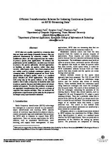
Fig. 7. Number of parallel operations (T SERM transforms (N = 64, C = 1).
PERM
) of PERM
and parallel
(16) We now draw a comparison on the computation time between the above block partitioning scheme and the direct parallelizaand denote the tion of SERM . Let time complexity of parallel addition/multiplication with PERM factorization and SERM factorization, respectively. For above block partitioning strategy, we have (17)–(20) shown at the bottom of the page. First, the number of effective processors can be up to (1/4) for PERM integer transform. From (17) and (18), it is easy to show that the costs of multiplication and addition are both when and are and , respec. By contrast, the number of effective tively, when processors cannot exceed for SERM transform and, therefore, for or , the time of multiplication and , respectively. and addition remains Table I lists the order of multiplications and additions for and PERM for processor number and SERM . Generally speaking, PERM is at least not worse . When than SERM for the processor number of order , there is no change in the processor number becomes SERM while the performance of PERM improves still. and , comFigs. 7 and 8 are examples for paring the performance of PERM and SERM with respect to the processor number. As can be seen in Fig. 7, the SERM
Fig. 8. Speedup of PERM 64, C = 1).
over parallel SERM
integer transforms (N =
complexity remains the same after the processors are more than 64, whereas PERM complexity continues to decrease. Of course, since communications and other overheads have been ignored, the above block partitioning strategy is only an illustration of what can be done. In practice, the blocking can be flexible to satisfy different requirements. For instance, to accommodate as many processors for parallel computing as possible, we could use multilevel binary partitioning. Although the total problem size of PERM , distinct from that of PERM , also drops (yet slower) as the level increases, the number of effective rows in each matrix can remain uncomponents changed: at level , there are altogether
(17)
(18)
(19) (20)
4682
IEEE TRANSACTIONS ON SIGNAL PROCESSING, VOL. 54, NO. 12, DECEMBER 2006
updated in a single step, whereas the number for PERM is . This trait is conducive to row allocation to efficiently utilize processor resources. For instance, assuming is a multiple of , the parallel complexity of muleach . tiplication and addition for both cases is
Now scale
by
, where we have
VI. EXAMPLES We demonstrate our PERM factorizations by a commonly used transform: discrete Fourier transform (DFT). A. Example: 9-by-9 DFT Matrix The
-by-
DFT matrix is defined by ; see the first equation at the bottom of the page. Without the loss of generality, suppose and . Since , should be scaled to implement perfectly reversible integer transform. Factorization: From (5), 1) PERM , where we have
Then
we
can
obtain
PERM factorization, , where all PERMs from right to left can be filled one by one into a matrix of the same size as ; see the equation at the bottom of the page. We call this matrix an integer transform matrix of . Factorization: In order to keep the phys2) PERM in ical equivalents of the original transform, we scale a proportional way: . From (6), we have , where
Likewise, we can store all PERMs in a 9-by-9 matrix as we did is written in Section VI-A1, except that the last block-row of along the diagonal downwards. Finally, after overwriting the , bottom right element with the last one of , i.e., as shown in the equawe get an integer transform matrix of tion at the bottom of the next page. Clearly, the storage of PERM
SHE et al.: MATRIX FACTORIZATIONS FOR PARALLEL INTEGER TRANSFORMATION
integer transform does not increase in comparison with that of the original DFT transform. VII. CONCLUDING REMARKS In the above discussions, we have presented PERM factorizations for parallel reversible integer transforms based on block factorizations. Compared with SERM factorizations, they offer improved parallel performance. Particularly, they increase the degree of parallelism and thus accommodate more processors. Since the PERM factorization and the corresponding integer transforms can all be calculated at the block level, we also expect increased efficiency in sequential computation with some matrix computation software (such as BLAS) speeding block operations. Consequently, PERM factorizations are attractive for large matrix integer transforms. Considering the flexibility of the scaling modification, PERM could be more promising in real-world applications. One problem is that the problem size gradually drops when level increases, which will probably reduce the availability of processors. This cannot be ignored, especially when PERM is employed with relatively more processors. The key to applying PERM factorizations is the proper choice of the block partitioning strategy. Including other necessary factors such as the communications, our future work will study this problem systematically and test the performance by further experimentation. APPENDIX A DEFINITION AND PROPERTIES OF DET In this Appendix, we give a simple introduction of the DET used in BLUS factorization. Interested readers may refer to [11] and [12] for details. We shall use
to denote a square block matrix with rows and columns of are of the same size. Before defining DET, blocks. Assume . we first define an auxiliary matrix function Definition 1: Given a block matrix , is recursively defined as follows. , . i) For ii) For , if is invertible, then .
4683
, if iii) For exists and is is defined by
invertible,
then
, where notation for with and , Definition 2: Given a block matrix sively defined as follows. , . i) For ii) For , if is defined, then and is defined by
Some important properties are listed as follows. Triangular Property: Assume and fined. If , Scaling Property: ..
is a . is recur-
exists
is de, then
.
..
.
where ( ) and ( , ) should be invertible. This property, as a counterpart of that of matrix determinant DET, is an important guarantee of the flexibility and practicability of the scaling modification. APPENDIX B TRANSFORM-ERROR CONTROL As mentioned in Section IV, one disadvantage of PERM factorizations is that larger block size and more factorization levels result in more rounding operations and possibly higher transin (1) and (2) can actuform error. However, noticing that ally be any nonlinear operator, we may keep more bits after the decimal point (e.g., rounding to hundredths or thousandths) to
4684
IEEE TRANSACTIONS ON SIGNAL PROCESSING, VOL. 54, NO. 12, DECEMBER 2006
effectively reduce the transform error. This can be justified by the error bounds given in [9] and [12]. , we introduce Given a factorization diagonal matrices to label the positions of pos. For sible rounding error in the transformation with , , example, . Let be the final error vector. If we consider the largest possible error, the error bound [9, Section VII] can be written as
(21) where is the unit roundoff, defined as the largest error that can occur in one rounding operation. Alternatively, if we care about the mean error, by characterizing the rounding errors as independent random noises, it can be formulated as [12, Section 2.4]
[7] A. R. Calderbank, I. Daubechies, W. Sweldens, and B.-L. Yeo, “Wavelet transform that map integers to integers,” J. Appl. Comput. Harmon. Anal., vol. 5, no. 3, pp. 332–369, 1998. [8] P. Hao and Q. Shi, “Invertible linear transforms implemented by integer mapping,” (in Chinese) Sci. China, ser. E, vol. 30, no. 2, pp. 132–141, 2000. [9] ——, “Matrix factorizations for reversible integer mapping,” IEEE Trans. Signal Process., vol. 49, pp. 2314–2324, 2001. [10] ——, “Proposal of reversible integer implementation for multiple component transforms,” in ISO/IEC JTC1/SC29/WG1N1720, Arles, France, Jul. 3–7, 2000. [11] Y. She and P. Hao, “Block TERM factorization of uniform block matrices,” Sci. China, ser. F, vol. 47, no. 4, pp. 421–436, 2004. [12] Y. She, “Matrix factorizations for efficient implementation of linear transforms,” (in Chinese) Master’s thesis, Peking Univ., Beijing, China, 2003. [13] P. Hao, “Customizable triangular factorizations of matrices,” Linear Algebra Applicat., vol. 382, pp. 135–154, 2004. [14] Y. She and P. Hao, “On the necessity and sufficiency of PLUS factorizations,” Linear Algebra Applicat., vol. 400, pp. 193–202, 2005. [15] G. Plonka, “A global method for invertible integer DCT and integer wavelet algorithms,” Appl. Comput. Harmon. Anal., vol. 16, pp. 90–110, 2004.
(22)
Yiyuan She was born in China in 1978. He received the B.Sc. degree in mathematics and the M.Sc. degree in electrical engineering from Peking University, Beijing, China, in 2000 and 2003, respectively. He is currently pursuing the Ph.D. degree in statistics at Stanford University, Stanford, CA. He was a Visiting Graduate Student at Queen Mary, University of London, London, U.K., in 2003. His research interests include signal processing, machine learning, statistical computing, and bioinformatics.
is the variance of noise in one dimension and is where the Frobenius-norm. These results also apply to block matrices, and the only diffor error propagation beference is that the position matrix comes more specific. It is theoretically hard to find the optimal factorization minimizing (21) or (22). However, we may lower or to reduce the transform error, since we can flexibly choose an arbitrary as used in (1) and (2). operator In summary, with quantitative error control formulas (21) and (22), we can determine the appropriate transform precision by choosing a proper rounding operator, thus achieving both perfect reversibility and very good transform-error control. (Interested readers may refer to [12] for details.)
Pengwei Hao (M’98) was born in the north of Shaanxi Province, China, in 1966. He received the B.Sc. degree in computer science and the M.Sc. degree in computer graphics from Northwestern Polytechnical University, Xi’an, China, in 1988 and 1994, respectively, and the Ph.D. degree in image processing from the Institute of Remote Sensing Applications, Chinese Academy of Sciences, Beijing, China, in 1997. From 1997 to 1999, he was a Lecturer at the Center for Information Science, Peking University, Beijing. In 2000, he was a Visiting Scientist for three months with the Centre for Vision, Speech, and Signal Processing, University of Surrey, Surrey, U.K. In 2002, he became a Lecturer at Queen Mary, University of London, London, U.K. He is also currently an Associate Professor with the Center for Information Science, Peking University. His research interests include data and image compression, data hiding, signal sampling and reconstruction, and computer graphics.
REFERENCES [1] H. Blume and A. Fand, “Reversible and irreversible image data compression using the S-transform and Lempel-Ziv coding,” in Proc. SPIE, 1989, vol. 1091, pp. 2–18. [2] A. Zandi, J. D. Allen, E. L. Schwartz, and M. Boliek, J. A. Storer and M. Cohn, Eds., “CREW: Compression with reversible embedded wavelets,” in Proc. IEEE Data Compression Conf., Snowbird, UT, 1995, pp. 212–221. [3] A. Said and W. A. Pearlman, “An image multiresolution representation for lossless and lossy compression,” IEEE Trans. Image Process., vol. 5, pp. 1303–1310, 1996. [4] W. Sweldens, “The lifting scheme: A custom-design construction of biorthogonal wavelets,” J. Appl. Comput. Harmon. Anal., vol. 3, no. 2, pp. 186–200, 1996. [5] F. A. M. L. Bruekers and A. W. M. van den Enden, “New networks for perfect inversion and perfect reconstruction,” IEEE J. Sel. Areas Commun., vol. 10, pp. 130–137, 1992. [6] I. Daubechies and W. Sweldens, “Factoring wavelet transforms into lifting steps,” J. Fourier Anal. Applicat., vol. 4, no. 3, pp. 247–269, 1998.
Yakup Paker (M’74) received the bachelor’s degree in electrical engineering from Istanbul Technical University, Turkey, in 1958 and the M.S. and Ph.D. degrees from Columbia University, New York, in 1961 and 1965, respectively. He is an Emeritus Professor of parallel computing at Queen Mary, University of London, London, U.K. He held academic positions at Middle East Technical University, Ankara, Turkey; the University of Westminster, London, U.K.; and Rennes University, Rennes, France, before joining Queen Mary as a full Professor in 1990. His research interests have included computer systems architectures and parallel computers, real-time architectures for video processing, virtual studios, three-dimensional TV, and digital broadcasting convergence. He has undertaken a range of collaborative research projects, funded by the European Union and the British government, which have included developing a multiprocessor architecture and systems software for real-time video processing, a customized TV terminal, an advanced set-top box based interactive TV, and systems architecture for three-dimensional TV. He has published extensively and is the author/editor of a number of books and proceedings.