MATRIX METHOD FOR ENERGY RATING CALCULATIONS OF PV MODULES G. Friesen, D. Chianese, S. Rezzonico, A. Realini, N. Cereghetti, E. Burà LEEE-TISO, Laboratory of Energy, Ecology and Economy University of Applied Sciences of Southern Switzerland (SUPSI) CP 110, CH-6952 Canobbio Phone: +41 91 / 935 13 56, Fax: +41 91 / 935 13 49 Internet: http://www.leee.dct.supsi.ch, e-mail:
[email protected]
ABSTRACT: A simple comparison of the manufacturer’s declared electrical characteristics at STC of photovoltaic modules does not permit determination of electrical yield. To better address the need of the future market an Energy Rating (ER) procedure based on matrix calculations is under development at the LEEE-TISO and other institutes. The present work explores the advantages and limits of the matrix method for calculations of the annual energy production of a module, placed in a fixed open-rack structure, using just a power matrix P(Gi, Ta) linked to a climatic condition matrix N(Gi, Ta) of the same dimensions. The comparison of the real module energy production with the matrix method calculated energy production is used to quantify the inaccuracy due to the exclusion of some parameters like diffused light and spectral response. The analysis of PV modules will be restricted to incident irradiance Gi and ambient temperature Ta. The matrix method can be implemented easily through the use of a simple spreadsheet and the use of a meteo program as Meteonorm. With a minimum of information (monthly meteo data, orientation and inclination of a PV system) a system designer can easily calculate the PV module Energy Rating with a good level of precision. Keywords: Performance, PV Module, Qualification and Testing
1 INTRODUCTION Currently the main parameter an end-user uses to decide which PV-module among the products he will select from those available on the market for his PV installation is the manufacturer’s declared maximum power output Pn measured under Standard Test Conditions (STC: 1000W/m², Tc=25°C, AM1.5 spectrum). The problem is that this nominal power Pn only partially describes module performance and does not give any information to the end-user or PV-installer about the energy production and quality of a module. The main difficulty lies in the fact that the manufacturer’s supplied power values are not always correct [1] and consequently they can not be used for a precise energy rating calculation or for a realistic intercomparison of different module types or different producers. In fact two modules with equal declared power may have dissimilar energy production. In order to answer to the question “How much energy does this module produce?” at the LEEE-TISO test centre, the most commonly sold modules on the market undergo a series of tests in order to examine their quality and reliability in terms of energy production but also in terms of power and power degradation over time [1]. Based on these test results, a new energy rating method, called the matrix method, is under development at the LEEE-TISO. For the PVplanner the matrix method should lead to a quick and simple procedure for the calculation of the annual energy production of a specific module and the evaluation of various technologies.
2 ENERGY RATING MEASUREMENTS The results here presented are based on the measurements of the 7th and 8th test-cycle of the duration of 15 months each. For each cycle a maximum of 36 modules can be tested (18 different types or manufacturers). Some modules underwent both testcycles in order to investigate the behaviour over a longer period and the reproducibility of the power matrix under
various climatic conditions. The following module technologies have been investigated: 11 sc-Si, 12 mc-Si, 4 a-Si and 2 CIS. The test stand of the LEEE-TISO (Lat.: 46°01’, Long.: 8°57’) consists of an outdoor construction with fixed mounting structure that has been placed at –7° south and tilted at 45°. The modules, two for each type, are linked to single MPPTs adapted to their respective ranges of voltage and current. The operation of each module at their maximum power point simulates real operating conditions as present in PV-systems. After a preliminary period of exposure in which the different modules reveals a technology dependent initial degradation [1], the electrical parameters (Im, Vm and Pm) and the back of module temperature Tbom of each module were measured. The electrical behaviour of the modules in operation is measured with respect to the following meteorological parameters: incident irradiance Gi, global irradiance G0, diffused irradiance Gdiff and ambient temperature Ta. The module data are stored simultaneously with the meteo data in one-minute intervals, from 5:00 to 22:00 o’clock. Finally the 1 year data of each module are converted into a power matrix and the meteo data into a meteo matrix. These experimental data are used for the development and the evaluation of the matrix method.
3 MATRIX METHOD 3.1 Energy Rating Calculations The matrix method is an Energy Rating (ER) procedure based on matrix calculations. The only input parameters needed are a PV-module power matrix and a meteo matrix of a specific site. The energy production of the module is then obtained by multiplying the elements of the power matrix P(Gi,Ta) by the corresponding climatic condition matrix N(Gi,Ta) elements.
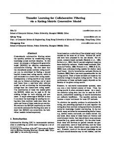
3.2 Power matrix The power matrix P(Gi, Ta) of a module gives information about the PV-module power in dependence
of incident irradiance (Gi) and ambient temperature (Ta).
general a PV-installer does not have the real meteo matrix of the site in which he wants to install the modules. So he has to look for available meteo data and generate from these a meteo matrix of the site. Usually the basic meteorological parameters available are those of the monthly horizontal plane irradiation G0 and the average ambient temperature Ta. By importing these monthly values into a program as METEONORM [4] and by selecting the orientation and tilt angle of the modules the hourly values Gi and Ta can be generated. A simple sorting of this data leads to the final meteo matrix.
Figure 2: Measured power matrix Praw(Gi, Ta) The matrix elements are obtained by taking the resulting average power from 1 year monitoring for each single climatic condition (Gi,Ta). Figure 2 shows an example of a measured raw power matrix. The raw power matrix Praw(Gi,Ta) is then filtered. All climatic conditions with a low event number (N20%) are ignored. High standard deviations mainly correspond to erroneous measurements or to very bad or rare climatic conditions. The last step consists of a smoothing and extension of the raw matrix to the final matrix (see Figure 3).
Figure 4: Measured meteo matrix N(Gi, Ta)
4 OUTPUT OF THE MATRIX METHOD The Matrix method can be easily implemented through the use of an Excel spreadsheet and a program as METEONORM. The meteo data used for the calculation can be either a user defined matrix, a selection of matrices that represents typical European climates or a meteo matrix generated from standard years available from existing standards. An example on how the output from the matrix calculations can be represented is shown in Table 1 and in Figure 5. Table 1 shows the annual Energy production in kWh and kWh/Wp for different European sites and for a user defined site. Figure 3: Final power matrix P(Gi, Ta) The final matrix covers all possible climatic conditions from –5°C to 40°C and from 50W/m² to 1100W/m². All power matrices have a grid mesh size of 10 W/m² x 1 °C. Other mesh sizes can be used. How the mesh size influences the energy rating calculations is described in more detail in a previous publication of the LEEE-TISO [2]. Alternative methods to measure a power matrix of a PV module are under investigation in other institutes [3]. The main difference with the other measurement procedure lies in the fact that indoor measurements are used for the generation of P(Gi, Tc), which implies the need for a transformation of the module temperature dependent matrix P(Gi, Tc) to the ambient temperature dependent matrix P(Gi, Ta). 3.3 Meteo matrix The meteo matrix N(Gi,Ta) of a module gives information about how many times N the climatic condition (Gi,Ta) occurs during 1 Year. From the LEEETISO test stand measured meteo data, the real meteo matrix can be extracted for each test cycle (Fig. 4). In
Manufacturer Module name
LEEE-TISO XXX Serial Nr. XX-100 Material
Annual Energy Production [kWh] [kWh/Wp] * Lugano 114.27 1.18 * Zürich 105.32 1.09 * Davos 132.87 1.37 * Rome 153.64 1.59 * Stockholm 104.08 1.08 User defined 115.75 1.20 Site name Azimuth [°] Inclination [°] example -7 45 *open-rack (45°, south)
xx-xxx-xx mc-Si Power Pn 100 Pa 99.8 P0 97.8 P3 97.6 P6 96.8 P9 97.6 P12 96.4 P15 96.7 Wp 96.7
Table 1: Annual Energy Production in [kWh] and [kWh/Wp] The Energy production in terms of kWh/Wp depends also on the power value. Usually an end-user is obliged to use the manufacturer’s declared nominal power. Due to the incorrect or inconsistent definition of the nominal power an end-user gets a wrong image of the product. Only if the real power of the module is known a real figure of the kWh/Wp production can be made. The real power of the
at the LEEE-TISO tested modules is known and is shown in Table 1. The Test procedure and the definition of the different power values Pa, P0, P3, etc. is explained in detail in another publication [1]. Figure 5 shows, from the matrix method, resulting energy production during 1 Year vs. the maximum power point under real operating conditions. This graph helps an installer to select an appropriate inverter size for the site in which he wants to install the modules. In Rome the module produces the most energy at 70W and in Davos at 82W. User defined
Lugano
5
30
Zürich
Davos
Rome
Stockholm
E = e ⋅ Pstab
(1)
This means that by knowing the real stabilised power Pstab of a module and the coefficient e the Energy E can be directly calculated. The coefficient e represents the energy generated by 1W under specific climatic conditions. Each location has a coefficient e, which can be obtained by multiplying the single elements of the standard crystalline silicon power matrix to the elements of a meteo matrix. Figure 7 shows the standard 1W power matrix obtained by averaging all the in test cycle 7 and 8 measured and normalised power matrices of mono and poly crystalline silicon modules.
Total energy production [kWh]
20 18 16 14 12 10 8 6 4 2 0 10
15
20 25
35 40 45 50 55
60
Maximum Power P[W]
65
70
75
80 85
90
95 100
Figure 5: Energy production vs. Pmax under operating conditions and for different sites Figure 7: Standard 1W power matrix P(Gi, Ta) 5 ENERGY RATING OF c-Si MODULES th
th
A closer look at the 7 and 8 test cycle shows that for the majority of the mono- and poly-crystalline silicon modules the difference in energy production [kWh/Wp] is much smaller if the energy production is referred to the real power than to the manufacturer’s declared nominal power. This is in accordance to other publications [5,6]. Figure 6 shows the Energy production kWh/Wp of each measured module. 140
Energy production E [kWh]
120
E vs. Pn E vs. Pstab
100 80 60 40
20 0 0
10
20
30
40
50
60
70
80
90
100
110
120
Power P [W]
A closer look at the crystalline silicon modules showed that the energy rating of a module can be calculated with an aprox. accuracy of ±5.5% without measuring the power matrix of the specific module. Instead of the preciser procedure based on the more time consuming and complex measurement of the module power matrix, a single measurement of the real stabilised power at STC would also lead to the energy rating of a module. The problem is, how a PV-installer can get the real stabilised power of his module. To solve this problem there is the need for further improvements in the existing or draft standards and a quality control of the production lines and especially of the solar simulators and procedures used by the manufacturers to measure the nominal power. As described in another paper of the LEEE-TISO [1] the nominal power and tolerances are different for each manufacturer. Additionally, almost none of the manufacturer give information about the stabilised power or about how large the possible first degradation is. An alternative to overcome this problem would be that a PVinstaller tests all or some of the modules he wants to install at a test laboratory. Further studies and collaboration programmes to solve these problems are ongoing at the LEEE-TISO.
Figure 6: Energy production vs. Power for c-Si The empty dots represent the energy production vs. the nominal power. The difference between the best and the worst module is of 40%. The filled dots represent the real energy production, where the power of each module has been measured under the solar simulator of the LEEETISO test laboratory. In this case the difference between the best and the worst module is reduced to 11% and a linear relation (Eq. 1) between the energy production E and the power Pstab can be found.
6 ERROR ANALYSIS 6.1 Power matrix generation The power matrix generation, which consists in the filtering, smoothing and extrapolation of the raw power matrix, leads to an error in the final energy rating calculation. The error is given by the difference of the real measured energy production and the calculated production. The calculated energy Ecalc1 is obtained by multiplying the final power matrix (Figure 3) with the measured meteo matrix (Figure 4). Table 2 shows the
error ∆Emeas-Ecalc1 for test-cycle 7. The final matrix has been generated either from the data of an entire year or from a single month, in this case of the month July. By generating the matrix with the data of a year the average error is of aprox. 0.4 %. Once the accuracy of the matrix method is verified by comparing real module energy production, measured for a whole year, with the estimated energy rating, a reduced amount of data for the power matrix generation has been tried. The use of 1 month instead of 1 year leads to a small increase in the average error of aprox. 0.4%, but only if thin film technologies and non-standard modules are excluded from this study. Due to seasonal variations and degradation effects of thin films it is not possible to estimate the energy of a whole year with the outdoor measurements of a single month. The study showed also that for c-Si modules the use of the winter months (November, December January) are inadequate for a matrix power generation. Another condition, which could negatively influence the final result, is the amount of available data. The 1 minute-interval-measured data gave good results. name & technology SW50T sc-Si Sunsl. sc-Si SM55 sc-Si MS3653 sc-Si M500A sc-Si BP275F sc-Si ASI16 sc-Si RSM50 mc-Si PW1000 mc-Si MSX83 mc-Si KC60 mc-Si GPV75P mc-Si ASE100 mc-Si APX90 mc-Si US64 a-Si DS40 a-Si max. error * avg. error *
Table 2:
Emeas [kWh/y] 44.48 58.61 61.26 57.29 58.94 78.73 42.61 57.56 105.38 82.91 69.41 76.61 117.94 80.00 83.54 49.51
∆Emeas-Ecalc1 [%] Year July -0.80 4.22 0.09 4.78 -0.46 0.63 -0.23 0.16 -0.39 1.00 -0.32 -0.16 -0.44 -1.50 -0.41 0.53 -0.44 -1.47 -0.01 0.90 -0.62 0.43 0.08 0.45 -0.29 1.16 -0.07 1.97 1.02 6.00 -0.20 4.56 1.02 0.37
1.97 * 0.80 *
∆Emeas-Ecalc2 [%] Meteonorm -0.21 -0.55 0.35 -0.53 -1.09 1.12 -1.76 -0.69 -1.39 1.83 -0.64 1.37 -0.88 -2.16 0.48 -2.00 2.16 1.09
Comparison of the real module energy production Emeas with the estimated energy rating Ecalc of cycle 7. (* without thin films and non standard modules)
6.1 Meteo matrix generation For cycle 7 the error introduced by the simulation of the annual meteo data (tilted irradiance Gi and ambient temperature Ta) starting from monthly meteo data (global irradiance G0 and ambient temperature Ta) has been investigated. Instead of using the 1 year monitoring obtained Gi and Ta data, the monthly average of the measured G0 and Ta were used. The introduction of this data into the Meteonorm programme together with the input of the azimuth and orientation of the test stand leads to estimated hourly irradiance and temperature data (G0, Ta). The generated meteo matrix from this data leads to an average error of aprox. 0.7%. As shown in Table 2 the two errors, power matrix generation error and meteo matrix generation error, thus leads to a total average error of aprox. 1.1%.
The final result is also influenced by the albedo coefficient used in the Meteonorm program. How large this error is currently under investigation. A further reduction of the error would be obtained by having a meteo simulation programme, output of which consists of minute data and not hourly data as in Meteonorm. In this way a higher resolution would be obtained. The advantages of minute values instead of hourly values are shown in Figure 8. Due to a lower resolution the in Figure 4 visible peak at high irradiances disappears.
Figure 8: Meteo matrix obtained from hourly data
7. CONCLUSIONS AND ONGOING WORK - The average accuracy of the matrix method for an open-rack mounted module is of aprox. 1.1%. - Each module has its own power matrix. - The true differences in energy between different c-Si technologies are in the range of ±5.5%. - The energy production of c-Si modules is proportional to their stabilised power. - There is a need to improve the manufacturer’s declared power and tolerance values. - The energy rating calculations of modules mounted in isolated or other structures are still under investigation. - There is a need to test the reproducibility of the power matrix in other sites with different climatic conditions. 8. REFERENCES [1] D. Chianese et al., Power and energy production of PV modules, PV in Europe, Rome, 2002 [2] D. Chianese et al., Energy Rating of PV modules, 17th EPVSEC, Monaco, 2001 [3] D. Anderson et al., Obtaining module energy rating from standard laboratory measurements, 17th EPVSEC, Monaco, 2001 [4] Meteonorm, www.meteotest.ch [5] S. Ransome et al., Analysis of measured kWh/kWP from grid tied systems – modelling different technologies worldwide with real data, 17th EPVSEC, Monaco, 2001 [6] D.L. King et al., Analysis of factors influencing the annual energy production of photovoltaic systems, 29th IEEE PVSC, New Orleans, 2002 9. ACKNOWLEDGEMENTS This project is financially supported by the Swiss Federal Office of Energy and the AET (Azienda Elettrica Ticinese).