Maximum Likelihood Estimation of Model Uncertainty in Predicting ...
Recommend Documents
x amplitude time [s] amplitude frequency [Hz] f. 1. 2. 1 f. )( 0 ix i i t rt xx e++= ... To determine the function's maxima the derivative of logarithmic function of .... 7,34. BOR1. -23457,49. -19,41. 13,38 x. -0,59. 3,53. GWWL. -23911,68 .... logar
is to solve a maximum likelihood problem with an added ℓ1-norm penalty term.
The ... Model Selection, Maximum Likelihood Estimation, Convex Optimization,.
Feb 24, 2010 - role of the distortion parameter q and give the conditions that guarantee asymptotic ... an asymptotic variance expression of the MLqE is very helpful to decide the ... derived and its efficiency is compared to the traditional MLE. ...
mean associated with f0 is zero which of course implies that the mean of Xi is θ. ..... discussed by Leger and Romano (1990) in the context of selecting the ...
Nov 23, 2010 - You can see in (14-3) that if this is the case, then the log-likelihood ...... second derivatives can be
Nov 23, 2010 - tion and hypothesis testing based on the maximum likelihood ...... However, it has been automated in cont
neutral mutation rate) and population growth rate from sequence samples using Metropolis- .... g is less than zero, some proportion of the rescaled times will.
f(xi|Â):. (3). Nevertheless, it is well known that the likelihood function of normal mixture ... Secondly, convergence can be quite slow when far ... We define also ... the development below if we make the two following restrictions. .... Since the l
Taking into account the advantages of Maximum Likelihood Method (most precise estimation), the statistical properties of MLEs (unbiasedness, consistency, ...
likelihood estimation, photon-correlated beams, point processes, quantum noise. I. INTRODUCTION. IN MANY imaging applications, it is desirable to accurately.
Implementing restricted maximum likelihood estimation in structural equation models. Structural Equation Modeling: A Multidisciplinary Journal, 20(1),. 157â167.
IEEE TRANSACTIONS ON CIRCUITS AND SYSTEMS FOR VIDEO TECHNOLOGY, VOL. 11, NO. 8, AUGUST ... wavelet coefficients. In practice, it is desirable to obtain an image free of com- ...... He joined Digital Media System Lab. Corporate.
average causal effect of the treatment on the outcome employing a counterfactual ... of epidemiology, Biostatistics and Occupational Health, cDepartment of.
Feb 24, 2010 - sity function p(x) for a random variable X, Shannon's entropy is ... must deal with the fact that the number of observations available is not large.
The probability density function of the three parameter generalized gamma type ... This distribution may be used as a generalized lifetime model, as it includes.
Jan 12, 2006 - Abstract The proportional hazards cure model generalizes Cox's proportional hazards model which allows that a proportion of study subjects ...
Abstract. In the present paper, the maximum likelihood estimates of the two parameters of a generalized gamma type model have been obtained directly by ...
We show how maximum penalized likelihood estimation can be applied to ... maximum likelihood estimator in the shared gamma-frailty model (and for the more.
problem of a resonate-and-fire model with random threshold. The model parameters are ... model, such trial-and-error approach depends mainly on researcher's ...
We show how maximum penalized likelihood estimation can be applied to ... maximum likelihood estimator in the shared gamma-frailty model (and for the more.
Feb 22, 2012 - complex systems theory. Examples include phenomena as diverse as internet traffic [5], geomagnetic activity. [6, 7] and rainfall patterns [8].
May 25, 2017 - derive the modified maximum likelihood estimators for Poisson regression model ... these equations requires using iterative methods, such as Newton ...... 4. Vaughan DC (2002) The generalized secant hyperbolic distribution.
imum-likelihood sequence estimation (MLSE) receivers operating ... the
performance of maximum-likelihood sequence estimation. (MLSE) was done in [2
] and ...
Maximum Likelihood Sequence Estimation in Channels with. Intersymbol
Interference and Noise Memory. Aleksandar Kavcic and José M. F. Moura1. Dept.
of ...
Maximum Likelihood Estimation of Model Uncertainty in Predicting ...
Nov 15, 2017 - Predicting Soil Nail Loads Using Default and Modified FHWA. Simplified ..... men ts. (aft er. [9]and so urce data fro m. [6â8]). W all. So iltype.
Hindawi Mathematical Problems in Engineering Volume 2017, Article ID 7901918, 14 pages https://doi.org/10.1155/2017/7901918
Research Article Maximum Likelihood Estimation of Model Uncertainty in Predicting Soil Nail Loads Using Default and Modified FHWA Simplified Methods Huifen Liu,1 Liansheng Tang,1,2 and Peiyuan Lin3 1
School of Earth Science and Engineering, Sun Yat-Sen University, Guangzhou, Guangdong 510275, China Provincial Key Laboratory of Mineral Resources and Geological Processes Guangzhou, Guangdong 510275, China 3 Department of Civil Engineering, Ryerson University, Toronto, ON, Canada M5B 2K3 2
1. Introduction Soil nails used to support ground excavations or reinforce existing slopes are most commonly installed using the drill and grout nail installation technique [1, 2]. A hole is first drilled into the ground or slope, then a steel bar is placed, and the hole is grouted. As such, a drilled and grouted soil nail is a composite cylindrical structure consisting of a nail tendon (steel bar) and a grout column. An installed composite cylindrical soil nail has two interfaces: the grout-soil interface and the grout-steel bar interface. When the nailed soil mass deforms, tensile loads develop along the nail initially at the grout-soil interface due to grout-soil interactions and then transfer (partially or fully) to the steel bar through grout-steel bar interactions. Hence, for a soil nail under working conditions both the grout column and steel bar components carry tensile loads. The
tensile loads of the steel bar can be easily estimated based on strain gauges mounted along the bar whereas the tensile loads of the grout column are difficult to measure directly. When the diameter of the grout column is very small or the grout column undergoes cracking, the total nail load can be roughly approximated as the steel bar load. However, it has been noted that in many cases the steel load itself cannot adequately account for the total nail load, especially when the grout column is intact and with large diameter [3–8]. Wentworth [6] and Banerjee et al. [7, 8] then developed a method to estimate the total nail load taking into account the portion that is carried by the grout column. In their study, the measured steel load of a soil nail was reported as the lower bound of total nail load while the sum of measured steel load plus theoretical maximum tensile load capacity of the grout column was reported as the upper bound of total nail load. The total nail load estimated using their proposed
2
Mathematical Problems in Engineering
method lies between the lower and upper bounds. Lin et al. [9] adopted the total nail load data interpreted by Wentworth [6] and Banerjee et al. [7, 8] as part of their nail load database and evaluated the accuracy of the default Federal Highway Administration (FHWA) simplified equation for prediction of maximum nail load under working conditions. The accuracy evaluation outcomes are unavoidably influenced by the method developed by Wentworth [6] and Banerjee et al. [7, 8] for estimation of total nail loads. Evaluation and consideration of model uncertainties are of great importance to reliability-based geotechnical designs, which have been discussed in [10]. Mainly included in the discussion are (1) methods for model uncertainty evaluation and model calibration which have been recently summarized by Dithinde et al. [11] and (2) an overview of existing work of model uncertainty characterization for different geotechnical models in the literature (e.g., shallow and deep foundations [12–17] and retaining structures [18–21]). The objective of this study is to evaluate the model uncertainty of the default FHWA simplified nail load equation using the lower and upper bound nail load data reported by Wentworth [6] and Banerjee et al. [7, 8]. The model uncertainty is quantified using a model bias defined as the ratio of measured to predicted maximum soil nail load. The maximum likelihood method is adopted in this paper, which has been widely demonstrated to be a powerful tool for estimation of statistical model parameters [i.e., mean and standard deviation or coefficient of variation (COV)] that is intended to describe a given data set [22–35]. The model bias of the default FHWA simplified nail load model is characterized as a normal or a lognormal random variable and the suitability of the two statistical models is compared using the Bayesian Information Criterion (BIC). This study also shows the calibration of the default FHWA simplified model for accuracy improvement using a regression approach summarized in [11]. A reliability-based design example of internal pullout limit state is provided in the end to show the benefit of using calibrated nail load model for design of soil nails. The present work is valuable to reliability-based analysis and design of soil nail internal limit states such as nail pullout failure and nail-intension failure.
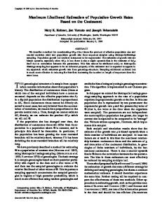
2. Performance Function of Soil Nail Pullout Limit State Figure 1 shows the geometry of a typical soil nail wall with a vertical facing and a horizontal back slope. The potential slip
𝐾𝑎 =
surface is assumed to extend from the toe to the top of the wall at an angle of (45+𝜙/2) degrees, dividing the whole soil nailing system into an active zone and a passive zone. Nail pullout failure takes place when the maximum nail tensile load exceeds its ultimate pullout capacity. The performance function of the soil nail pullout limit state, 𝑔, can be written as 𝑔 = 𝑃𝑚 − 𝑇𝑚 = 𝜆 𝑝 𝑃𝑢 − 𝜆 𝑇 𝑇𝑝 ,
where 𝑃𝑚 and 𝑇𝑚 are measured uncensored ultimate nail pullout capacity and maximum nail tensile load, respectively; 𝑃𝑢 and 𝑇𝑝 are predicted ultimate nail pullout capacity and predicted maximum nail tensile load, respectively; 𝜆 𝑝 and 𝜆 𝑇 are model biases accounting for prediction errors in 𝑃𝑢 and 𝑇𝑝 , respectively. Accordingly, 𝜆 𝑝 and 𝜆 𝑇 are defined as 𝜆 𝑝 = 𝑃𝑚 /𝑃𝑢 and 𝜆 𝑇 = 𝑇𝑚 /𝑇𝑝 , which are the ratios of measured to predicted values. In the FHWA soil nail wall design manuals [1, 2], 𝑃𝑢 can be calculated as 𝑃𝑢 = 𝜋𝐷𝐿 𝑒 𝑞𝑢 ,
(2)
where D is drill hole diameter, 𝑞𝑢 is ultimate bond strength of soil nails, and 𝐿 𝑒 is effective nail length as defined in Figure 1 and computed as cos (45∘ + 𝐿𝑒 = 𝐿 −
sin (45∘ +
𝜙 ) 2
𝜙 + 𝜃) 2
(𝐻 − 𝑧) ,
(3)
where 𝜃 is nail inclination angle; 𝜙 is soil friction angle; 𝐻 is wall height; and 𝑧 is depth of nail head. The FHWA soil nail design manuals [1, 2] also provide a default simplified model for computation of 𝑇𝑝 , which is expressed as 𝑇𝑝 = 𝜂𝐾𝑎 (𝛾𝐻 + 𝑞𝑠 ) 𝑆ℎ 𝑆V ,
(4)
where 𝜂 is empirical depth factor expressed as 𝜂 = 1.25𝑧/𝐻 + 0.5 for 0 < 𝑧/H ≤ 0.2, 𝜂 = 0.75 for 0.2 < 𝑧/𝐻 ≤ 0.7, and 𝜂 = 2.03–1.83𝑧/𝐻 for 0.7 < 𝑧/𝐻 ≤ 1; 𝑧 is depth of nail head; 𝐻 is wall height; 𝛾 is soil unit weight; 𝑞𝑠 is surcharge; 𝑆ℎ and 𝑆V are horizontal and vertical nail spacing, respectively; and 𝐾𝑎 is Coulomb active earth pressure coefficient expressed as
cos2 (𝛽 + 𝜙) 2
cos2 𝛽 cos (𝛽 − 𝛿) [1 + √sin (𝜙 + 𝛿) sin (𝜙 − 𝜔) / cos (𝛽 − 𝛿) cos (𝜔 + 𝛽)]
where 𝛽 is face batter angle; 𝜙 is effective soil friction angle; 𝜔 is back slope angle; and 𝛿 is interface friction angle between the wall face and soil.
(1)
,
(5)
To perform reliability-based design of soil nail pullout limit state using (1), the statistics (i.e., means and COVs) and distributions of the model biases 𝜆 𝑝 and 𝜆 𝑇 must be known.
Mathematical Problems in Engineering
3
Potential slip surface
be equal to the product of tensile strength of the grout and its cross-sectional area. Theoretically, the actual total nail load is larger than the steel load alone but smaller than the sum of steel load plus maximum grout column load capacity. In other words, the measured steel load is the lower bound of the total nail load while the sum of steel load plus grout column load is the upper bound. Wentworth [6] and Banerjee et al. [7, 8] reported a large amount of measured lower bound and upper bound nail load data for nails from ten soil nail wall sections that were wellinstrumented under working conditions. Detailed descriptions of the wall geometry, soil properties, and nail arrangement of the ten soil nail wall sections can be referred to the source documents [6–9] and thus only a brief summary is provided in Table 1 for brevity. Each nail in the walls has several measurement points and each point has a measured lower bound nail load and a measured upper bound nail load. These measured nail loads are summarized in Table 2. Predicted nail loads 𝑇𝑝 using the default FHWA simplified nail load model (see (4)) are also provided in Table 2 for comparison. Since it is the maximum nail load that could result in nail pullout failure, only the point giving maximum lower and upper bound nail load values was used for further analyses. In total, there are 112 maximum lower and upper bound nail load data points and thus each dataset has 𝑛 = 56 data points. As shown in Table 1, there were two walls (W6 and W7) built in soft to very soft clay which is rare case in practice since such soft soils cause additional stability and settlement concerns [1, 2, 36]. Hence, load data for these two walls (𝑛 = 11) were removed from further analyses. There are also questionable data for walls W9 (𝑛 = 3) and W10 (𝑛 = 6). Detail of explanations regarding these questionable data points can be found in [6–9]. The 𝑛 = 9 questionable data points were also excluded from further analyses. After filtering, the amount of data used in this study to carry maximum likelihood analyses is 𝑛 = 72 (italic in Table 2); each dataset has 𝑛 = 36 data points. These load data were collected from nails installed in frictional soils or cohesive-frictional soils with soil friction angles typically ranging from 30 to 40∘ and soil cohesion typically less than 10 kPa. The data are considered as longterm nail loads since they correspond to nail tensile loads that were recorded several months to several years after the end of construction of the soil nail walls.
Vertical spacing, S
Wall height, H
Active zone
Passive zone
Soil nails
Nail inclination, Le
45∘ + /2
Figure 1: Geometry of a typical soil nail wall.
Surrounding soil Nail grout
Steel rebar
Strain gauges
Figure 2: Measurement of nail loads under working conditions.
Lazarte [36] reports that 𝜆 𝑝 for 𝑃𝑢 follows a lognormal distribution with a mean of 1.05 and a COV of 0.24. Hence, one of the focuses of the present study is on characterization of 𝜆 𝑇 , which requires a broad database of measured nail loads (𝑇𝑚 ) as 𝜆 𝑇 is defined as 𝑇𝑚 /𝑇𝑝 . The database of 𝑇𝑚 used in this study for characterization of 𝜆 𝑇 is presented in the next section.
3. Database of Lower and Upper Bound Nail Loads under Working Conditions 3.1. Lower and Upper Bound Nail Load Data. Tensile loads along the steel rebar of a soil nail can be directly calculated using readings from strain gauges mounted on the steel, as shown in Figure 2. Usually, a pair of strain gauges is symmetrically mounted on the top and bottom of the steel bar. The steel load is then taken as the average of the two loads calculated based on the strain gauges. Tensile loads in the grout column are difficult to measure directly; however, the maximum loads that the grout column can carry would
3.2. Preliminary Analysis. Typical values of 𝛿 in (5) for computation of 𝐾𝑎 range from 1/2 𝜙 to 2/3 𝜙. In this study, 𝛿 is taken to be 1/2 𝜙. The influence of 𝛿 on accuracy evaluation outcomes of the default FHWA nail load equation is also examined later in this paper. Figure 3 shows plots of measured depth factors (𝜂) versus normalized nail depths (𝑧/𝐻). Measured depth factors are computed as 𝜂 = 𝑇𝑚 /𝐾𝑎 (𝛾𝐻 + 𝑞s )𝑆ℎ 𝑆V where 𝑇𝑚 are measured nail loads (i.e., lower and upper bounds). Depth factors computed using the FHWA simplified method are also plotted in Figure 3 for comparison. On average, the measured 𝜂 values using lower bound nail load data increase from about 0.3 at 𝑧/𝐻 = 0 to 0.5 at 𝑧/𝐻 = 0.2, then keep constant until 𝑧/𝐻 = 0.7, and decrease to about 0 at the bottom of the
Medium dense, poorly graded sand Silty sand, clayey silt Glacial sand, gravel Silty sand, stiff clay Clayey silty sand Soft to very soft clay Soft to very soft clay Silty, gravelly sand Residual soil and weathered rock Colluvium and highly weathered rock
Note. W1 = Swift-Delta S1; W2 = Swift-Delta S2; W3 = Polyclinic; W4 = Peasmarsh; W5 = Guernsey; W6 = IH30 R-SA; W7 = IH30 R-SB; W8 = San Bernadino Left and Right; W9 = Cumberland Gap 1988; W10 = I-78 Allentown G24 and G33. ∗ Laboratory results indicated 𝜙= 34∘ to 42∘ [7, 8]. In this study, 𝜙 is conservatively taken as 34∘ .
W10
W9
W8
W7
W6
W5
W4
W3
W2
W1
Wall
Wall geometry
Table 1: Summary of wall geometry, soil properties, and nail arrangement for soil nail walls reported in the source documents (after [9]and source data from [6–8]).
4 Mathematical Problems in Engineering
Mathematical Problems in Engineering
5
Table 2: Summary of measured lower and upper bounds of nail load reported in the source documents [6–8] at each measurement point and the corresponding 𝑇𝑝 using the default FHWA simplified nail load model. Wall
Figure 3: Measured depth factor versus normalized nail depth (lower and upper bounds).
wall (i.e., 𝑧/𝐻 = 1.0). The FHWA 𝜂 curve appears to be the envelope of the measured lower bound 𝜂 values. However, the measured upper bound 𝜂 values scatter widely from about 0.1 to about 1.8. The majority of the upper bound 𝜂 values are larger than predicted 𝜂 values using the default FHWA simplified method. Figure 4 shows plots of measured nail loads (𝑇𝑚 ) versus predicted nail loads (𝑇𝑝 ) using the FHWA simplified method. Bias values using measured lower bound 𝑇𝑚 fall within 0.5 and 1 for most cases whereas upper bound values of bias are typically within 1 and 2. Here, bias is defined as the ratio of measured to predicted nail load, that is, 𝑇𝑚 /𝑇𝑝 . These observations are consistent with those based Figure 3. This also suggests qualitatively that the default FHWA simplified equation (see (4)) is generally accurate on average. The cumulative distribution functions of the lower and upper bound bias data (𝑇𝑚 /𝑇𝑝 ) are shown in Figure 5. Bias data are examined in two forms, including raw bias values and logarithm of bias values. Visually, for both cases the
Default FHWA simplifed method
0 0
50
100 150 200 Predicted nail load, Tp (kN)
250
Lower bound data Upper bound data
Figure 4: Measured versus predicted nail loads using default FHWA simplified nail load equation (see (4)).
trends in the bias data can be adequately captured using first order polynomials, regardless of lower or upper bound bias data. This suggests that both raw and logarithm of bias values follow normal distributions. This is confirmed by the quantitative outcomes of the Kolmogorov–Smirnov tests applied to the four datasets shown in Figure 5. Hence, both lower and upper bound bias values can be taken as normally and lognormally distributed. Based on these findings, the bias of the default FHWA simplified equation is assumed to be normally and lognormally distributed. Quantitative outcomes of accuracy evaluation on the default FHWA nail load equation using maximum likelihood method are presented in the following.
4. Maximum Likelihood Estimation of Model Bias 4.1. Principle of Maximum Likelihood Estimation. The principle of maximum likelihood states that, for a specific statistical
Mathematical Problems in Engineering
7 best estimates for 𝜇ln and 𝜎ln are determined, they can be easily transformed to 𝜇 and COV using (e.g., [38]):
2
Standard normal variable
1
2 ) 𝜇 = exp (𝜇ln + 0.5𝜎ln
0 −1 −2
Upper bound data
2
Lower bound data
(8a)
2)−1 COV = √exp (𝜎ln
(8b)
The confidence interval of the log-likelihood functions can be determined using the likelihood ratio test as [39, 40]
1
1 2 , ln 𝐿 𝛼 = ln 𝐿 max − 𝜒𝛼;1 2
0 −1 −2 −2.0 −1.5 −1.0 −0.5 0.0 0.5 1.0 1.5 2.0 2.5 3.0 3.5 4.0 Bias or logarithm of bias, Tm /Tp or FH(Tm /Tp ) Raw bias value Logarithm of bias value
Figure 5: Cumulative distribution plots of bias and logarithm of bias using lower and upper bound bias data.
model (e.g., normal or lognormal distribution) used to fit observed data for a random variable 𝑋, the model parameters (e.g., mean and standard deviation or COV) would be the pair that maximizes the likelihood of all observed data. In this paper, the random variable 𝑋 is the bias of the FHWA method and the observed data are the measured lower and upper bound bias data. The log-likelihood of the measured lower and upper bound bias data can be written as (e.g., [23, 30, 37]) ln 𝐿 (𝜇, 𝜎 | 𝑎𝑖 , 𝑏𝑖 ) 𝑛 𝑎 −𝜇 𝑏 −𝜇 1 = ∑ln { [erf ( 𝑖 ) − erf ( 𝑖 )]} √2𝜎 √2𝜎 2 𝑖=1
(6)
if 𝑋 is a Gaussian random variable, and ln 𝐿 (𝜇ln , 𝜎ln | 𝑎𝑖 , 𝑏𝑖 ) 𝑛 (7) ln 𝑎𝑖 − 𝜇ln ln 𝑏 − 𝜇ln 1 = ∑ln { [erf ( 𝑖 ) − erf ( )]} √2𝜎ln √2𝜎ln 2 𝑖=1
if 𝑋 is a lognormal random variable. Here, 𝑎𝑖 and 𝑏𝑖 are lower and upper bound bias data, respectively; 𝜇 and 𝜎 are mean and standard deviation of bias, respectively. 𝜇ln and 𝜎ln are log-mean and log-standard deviation of bias, respectively; erf() is the error function; 𝑛 is the number of data points. Equations (6) and (7) can be understood as that the measured lower and upper bound bias data (𝑎𝑖 and 𝑏𝑖 , 𝑖 = 1, 2, . . . , 𝑛) are known input parameters whereas 𝜇 and 𝜎 and 𝜇ln and 𝜎ln are variables to be determined. The maximum likelihood method states that the best estimates for 𝜇 and 𝜎 and 𝜇ln and 𝜎ln are the pairs that maximize the loglikelihood function equations (6) and (7), respectively. These pairs are called the maximum likelihood estimators or the best estimates in this study. For the lognormal case, once the
(9)
where ln 𝐿 𝛼 is log-likelihood value corresponding to 𝛼; 𝛼 is specified level of significance for the confidence interval; 2 𝜒𝛼;1 = 100(1−𝛼) percentile point of a Chi-Square distribution with one degree of freedom. For example, if a confidence level 2 of 95% is desired (𝛼 = 0.95), then 𝜒0.95;1 is equal to 3.84 and ln 𝐿 𝛼 = ln 𝐿 max − 1.92. Closed-form solutions of best estimates for (𝜇, 𝜎) in (6) and (𝜇ln , 𝜎ln ) in (7) are not available in this study. Nonetheless, (6) and (7) can be solved numerically following four steps: (1) set the objective function 𝐺 = 1/ln𝐿 which is the reciprocal of the log-likelihood function; (2) set constraints for optimization as 𝜇 > 0 and 𝜎 > 0 for the normal case and 𝜎ln > 0 for the lognormal case; (3) find the pair of (𝜇, 𝜎) or (𝜇ln , 𝜎ln ) that minimizes the 𝐺 value for each case and calculate ln 𝐿 max as 1/𝐺; and (4) for the lognormal case, calculate the mean and COV values using ((8a) and (8b)). It was shown earlier through the Kolmogorov–Smirnov tests that the bias of the default FHWA simplified equation (see (4)) can be treated as a normal random variable or a lognormal one. The Bayesian Information Criterion (BIC) [41] can be adopted to further perform a comparison of suitability between these two statistical models. The BIC for a statistical model is calculated as BIC = −2 ln 𝐿 max + 𝑘 ln (𝑛) ,
(10)
where 𝑛 is number of data points; 𝑘 is number of model parameters. In this paper, 𝑘 = 2 since both the normal and lognormal distribution models have two model parameters, that is, mean and COV (or standard deviation). The criterion states that a smaller BIC value indicates a better fitting to the observed data. The BIC value of a statistical model can be further used to compute the probability of that model being the best among all competing models. This probability of being the best model is calculated as (e.g., [35, 42]) 𝑃best =
exp [−Δ 𝑖 (BIC) /2]
∑𝑟𝑗=1
exp [−Δ 𝑗 (BIC) /2]
,
(11)
where Δ 𝑖 (BIC) = BIC𝑖 − min{BIC𝑗 }, 𝑗 = 1, 2, . . .,𝑟; 𝑟 is number of candidate models; min{BIC𝑗 } is minimum value among all the BIC values. 4.2. Results of Model Bias Analysis. Measured lower and upper bound bias data (𝑛 = 36 for each) are input parameters 𝑎𝑖 and 𝑏𝑖 (𝑖 = 1, 2, . . . , 𝑛) in both (6) and (7). For the normal
8
Mathematical Problems in Engineering 0.50
0.50 95% confidence domain FH L 95 = −30.61
0.40 0.35
FH L G;R = −28.69
0.30 0.281 0.25
−30 −70
0.20
−40 −35 −50
0.15 0.10 0.5
0.6
0.7
95% confidence domain FH L 95 = −32.90
0.45 Estimated COV of bias
Estimated COV of bias
0.45
−60
1.03 0.8 0.9 1.0 1.1 1.2 Estimated mean of bias
−70
0.40 FH L G;R = −30.98
0.35 0.330 0.30 0.25 −40
0.20
1.4
1.5
(a)
−70
−60 −50
0.15 0.10
1.3
−35
0.5
0.6
0.7
1.03 0.8 0.9 1.0 1.1 1.2 Estimated mean of bias
1.3
1.4
1.5
(b)
Figure 6: Contour plots of likelihood function and 95% confidence interval: (a) normal and (b) lognormal.
distribution case as shown in Figure 6(a), the ln 𝐿 max was found to be −28.69 and the corresponding best estimates for mean and COV of bias of (4) were 1.03 and 0.281, respectively. ln 𝐿 max , best estimates of mean and COV of bias, were −30.98, 1.03, and 0.330, respectively, for the lognormal distribution case, as shown in Figure 6(b). In both cases the best estimated mean of bias is close to 1, suggesting that the default FHWA simplified equation for predicting maximum nail loads under working conditions is satisfactorily accurate on average. The spreads in prediction accuracy expressed as bias COV are fairly small, that is, about 30% for both cases. The 95% confidence intervals computed using (9) are also shown in Figures 6(a) and 6(b). For the normal case, the loglikelihood value corresponding to the 95% confidence level was −30.61. This is interpreted as that any pairs of estimated mean and COV of bias resulting in a log-likelihood value falling between −28.69 and −30.61 cannot be rejected as a reasonable pair of maximum likelihood estimates. All such pairs consist of the 95% confidence domain. The bias mean in the domain ranges from about 0.91 to 1.16 and the bias COV ranges from about 22% to 39%. From a practical point of view, these 95% confidence intervals are not significantly wide, suggesting that the analysis using the maximum likelihood estimation method is efficient. Similar observations can be made for the lognormal case based on Figure 6(b). Equation (10) was used to compute the BIC value for each statistical model and then the probability of being the best model was computed using (11). The BIC values are 64.54 and 69.12 for the normal and lognormal cases, respectively. The 𝑃best value is about 91% for the normal assumption whereas it is only 9% for the lognormal assumption. This means that the model bias of (4) is better described as a normal random variable. However, it should be cautious to take bias as a normal random variable for reliability analysis using Monte Carlo simulation technique as negative values could be generated. Negative values of bias are not possible based on the definition of bias, that is, measured to predicted nail loads.
The above analysis outcomes are based on the assumption that 𝛿/𝜙 = 1/2. The influence of 𝛿/𝜙 was found insignificant on computed outcomes of the best estimates for mean and COV of bias, ln 𝐿 max , and 𝑃best regardless of the normal or lognormal case, as shown in Figures 7 and 8. The influence is even smaller for 𝛿/𝜙 within the typical range of 1/2 to 2/3. Hence, the adoption of 𝛿/𝜙 = 1/2 in the previous analyses is justified. This value will be also used in the analyses to follow.
5. Calibration of FHWA Simplified Method for Accuracy Improvement The regression approach introduced in [11] can be adopted to calibrate the default FHWA nail load equation (see (4)) for accuracy improvement. The approach is to regress the model bias against each input parameter in the default FHWA nail load equation, through which empirical functions describing the relationships between the model bias and each input parameter are developed. These empirical functions are then introduced to the default FHWA equation as multiplicative components, which results in a modified FHWA simplified nail load equation. The calibration outcomes in this study are shown below. The measured lower and upper bound bias data are plotted against predicted nail loads and shown in Figure 9. In general, both lower and upper bound bias data decrease with increasing magnitudes of predicted nail loads. This trend is quantitatively confirmed by applying the Spearman’s rank correlation test to the datasets in Figure 9. Spearman’s 𝜌 values are negative and the 𝑃 values are less than 0.05 for both cases, implying the presence of negative correlations of the datasets at a level of significance of 5%. The measured bias data were further plotted against each input parameter in (4); the plots are shown in Figure 10. Based on Figure 10 and Lin et al. [9], it is judged that the primary source of correlation between bias and predicted nail load is due to correlation
9
1.5
0.50
1.4
0.45
1.3
0.40
Best estimate of COV of bias
Best estimate of mean of bias
Mathematical Problems in Engineering
1.2 1.1 1.0 0.9 0.8 Typical range of interest
0.7 0.6
0.35 0.30 0.25 0.20 0.15
Typical range of interest
0.10 0.05
/ = 1/2
0.5 0.0
0.1
0.2
0.3
2/ 3
0.4 0.5 0.6 0.7 Ratio of to , /
/ = 1/2
0.00 0.8
0.9
0.0
1.0
Normal Lognormal
0.1
0.2
0.3
2/ 3
0.4 0.5 0.6 0.7 Ratio of to , /
0.8
0.9
1.0
0.9
1.0
Normal Lognormal (a)
(b)
−50
100 Probability of being the best model, P<?MN (%)
Maximum value of log-likelihood function, FH L G;R
Figure 7: Influence of 𝛿/𝜙 on maximum likelihood evaluation outcomes of: (a) bias mean and (b) bias COV.
−45 −40 −35 −30 −25 −20 Typical range of interest
−15 / = 1/2
−10 0.0
0.1
0.2
0.3
2/ 3
0.4 0.5 0.6 0.7 Ratio of to , /
90 80 70 60 50 40 Typical range of interest
30 20 10 / = 1/2
0 0.8
0.9
1.0
0.0
0.1
0.2
0.3
2/ 3
0.4 0.5 0.6 0.7 Ratio of to , /
0.8
Normal Lognormal
Normal Lognormal (a)
(b)
Figure 8: Influence of 𝛿/𝜙 on maximum likelihood evaluation outcomes of (a) maximum value of log-likelihood function, ln 𝐿 max ; (b) probability of being the best model, 𝑃best .
between bias and tributary area (Figure 10(d)). As a result, (4) can be modified as 𝑇𝑝 = 𝜂𝑀𝐾𝑎 (𝛾𝐻 + 𝑞𝑠 ) 𝑆ℎ 𝑆V ,
(12)
where 𝑀 is empirical modification factor relating to tributary area (𝑆ℎ 𝑆V ). Other input parameters are as defined earlier in this paper. Different simple expressions for 𝑀 were examined and the one that yields minimal bias COV is 𝑀 = 𝑎 exp (𝑏
𝑆ℎ 𝑆V ), 𝐴𝑡
(13)
where 𝑎 and 𝑏 are two empirical constants to be determined; 𝐴 𝑡 = 1.5×1.5 m2 = 2.25 m2 is defined as typical tributary area which is intended to make 𝑀 dimensionless. The values of 𝑎 and 𝑏 were determined by adjusting their values until the best estimate for bias mean is equal to 1 while the best estimate for bias COV is as small as possible for each case. Figure 11 shows that the estimated bias COV is dependent on the empirical constant 𝑏 (Figure 11(a)) but is not influenced by the empirical constant 𝑎 (Figure 11(b)). The lowest values of bias COV are achieved at 𝑏 = −0.60 for both. Knowing the 𝑏 value, the 𝑎 values were computed as 1.7595
10
Mathematical Problems in Engineering 5
Bias, Tm /Tp
4
3
2
1
0 0
50 100 150 Predicted nail load, Tp (kN) Data Lower bound Upper bound
200
Spearman’s
P value
−0.41 −0.61
0.01 0.00
Figure 9: Bias versus predicted nail load using default FHWA simplified method (see (4)).
and 1.7608 for the normal and lognormal cases, respectively. The 𝑎 values were rounded up to two decimal places, giving 𝑎 = 1.76 for both cases. The estimated minimal COV of bias for (12) are 0.248 and 0.283 for the normal and lognormal cases, respectively. Both bias COV values are smaller than those for the default FHWA nail load equation (see (4)). The results of accuracy evaluation are summarized in Table 3.
6. Reliability-Based Design Example of Pullout Limit State of Soil Nails This section presents a reliability-based design example of pullout limit state for soil nails using the default and calibrated FHWA simplified nail load equations. The bias of each equation is taken as normal and lognormal random variables. Through the design example, the practical influence of selection of bias statistical models on design outcomes is shown. The benefit of using the calibrated nail load equation is also demonstrated. The problem geometry of the example wall has been shown in Figure 1. The example wall is taken from the FHWA soil nail wall design manual [1]. Deterministic input parameters for this design example include wall height 𝐻 = 10 m, facing batter = 0∘ , back slope angle = 0∘ , nail spacing 𝑆ℎ = 𝑆V = 1.5 m, nail inclination angle 𝜃 = 15∘ , and drill hole diameter 𝐷 = 150 mm. A total of 7 rows of nails were used with the first row installed at a depth of 0.5 m from the top of the wall which is typical [1, 2]. The normalized nail depth at each row is 𝑧/H = 0.05, 0.2, 0.35, 0.5, 0.65, 0.8, and 0.95. The potential sliding surface is assumed to be linear and extends from the toe of the wall to the top. The soil is medium dense silty sand with clay seams. According to [1], the design values of soil unit weight, soil friction angle, soil cohesion, and ultimate nail bond are
𝛾 = 18 kN/m3 , 𝜙 = 33∘ , 𝑐 = 0 kPa, and 𝑞𝑢 = 100 kPa, respectively. The bias mean is assumed to be 1 for both 𝜙 and 𝛾 in this study. The corresponding bias COV values are taken as 0.10 and 0.05, which are typical [43, 44]. Lazarte [36] reports that the bias of 𝑞𝑢 has a mean of 1.05 and a COV of 0.24. These values are adopted in this example design. All the random variables are assumed to be lognormally distributed except for the bias for 𝑇𝑝 . The main design parameter in this example is the nail length at each depth which is required to satisfy a targeted reliability index, 𝛽𝑇 . For reliability-based design of internal limit states of reinforced soil walls, the target reliability index is often selected as 𝛽𝑇 = 2.33 (probability of failure equal to 1/100), for example, [39, 45]. Hence, 𝛽𝑇 = 2.33 is chosen here. In addition, a minimal value of 0.5H is imposed to the nail length as per the requirement of the FHWA soil nail wall design manuals [1, 2]. That is to say, for nails with length shorter than 0.5H but satisfying 𝛽𝑇 = 2.33, these nails will still be lengthened to be 0.5H. The Hasofer-Lind method was used to compute the reliability index of the design using (1). The nail length at each depth was adjusted until the computed reliability index is equal to the target one, that is, 2.33. The Hasofer-Lind method can be easily implemented using Excel spreadsheet [46, 47]. The design outcomes are plotted in Figure 12 and summarized in Table 4. The required nail lengths for the bottom two layers of nails were found to be less than 0.5H (values in the brackets in Table 4); as a result, a value of 0.5H was used. The differences in required total nail length are small given normal or lognormal distribution of the bias of 𝑇𝑝 regardless of the fact that the default or modified FHWA simplified nail load equation is used, that is, 4.78 versus 4.88 and 4.59 versus 4.65. However, the required total nail lengths using the modified equation for 𝑇𝑝 (see (12)) are always less (about 5%) than those using the default equation for 𝑇𝑝 (see (1)), that is, 4.59 versus 4.78 and 4.65 versus 4.88. This highlights the benefit of performing model calibration and using the calibrated nail load equation for design.
7. Summary and Conclusions This study presents a maximum likelihood-based evaluation of the accuracy of the default FHWA simplified equation for prediction of maximum soil nail loads under working conditions. Accuracy was quantitatively expressed as the statistics of the model bias where bias is defined as the ratio of measured to predicted nail load. The measured lower and upper bound data of nail loads were taken from Wentworth [6] and Banerjee et al. [7, 8]. Accordingly, the computed bias values are divided into lower and upper bound datasets. Kolmogorov–Smirnov tests were applied to the lower and upper bound bias datasets and the outcomes showed that both datasets can be considered following normal or lognormal distribution. Hence, the maximum likelihood estimation was carried out for two cases: (1) bias is a normal random variable and (2) bias is a lognormal random variable. The maximum likelihood estimation outcomes showed that, based on the collected data, the default FHWA simplified nail load equation was found to be satisfactorily accurate on average and the spread in prediction accuracy expressed as
0.20 0.25 0.30 0.35 0.40 Active earth pressure coefficient, Ka
Data
0.46 0.96
P value
0.10 0.22
0.56 0.20
Lower bound Upper bound
(a)
(b)
5
5 Default FHWA simplified method
Default FHWA simplified method
4
4
3
3
Bias, Tm /Tp
Bias, Tm /Tp
Spearman’s
0.45
2
1
2
1
0
0 50
100 150 200 250 300 350 400 450 Overburden pressure at depth of wall base, H + qs (kPa) Data
Spearman’s
P value
0.09 −0.37
0.60 0.03
Lower bound Upper bound
1.0
1.5 Data Lower bound Upper bound
(c)
2.0 2.5 Tributary area, Sℎ S (G2 )
3.0
3.5
Spearman’s
P value
−0.43 −0.18
0.01 0.31
(d)
Figure 10: Bias versus input parameters of the default FHWA simplified nail load equation (see (4)): (a) empirical depth factor, 𝜂; (b) active earth pressure coefficient, 𝐾𝑎 ; (c) overburden pressure at base of the wall, 𝛾ℎ + 𝑞𝑠 ; (d) tributary area, 𝑆ℎ 𝑆V .
Table 3: Maximum likelihood analysis outcomes for both default and modified FHWA simplified nail load equations expressed as 𝑇𝑝 = 𝜂𝑀𝐾𝑎 (𝛾𝐻 + 𝑞𝑠 )𝑆ℎ 𝑆V . Method Default FHWA simplified method Modified FHWA simplified method
Note. 𝐴 𝑡 = 1.5 × 1.5 m2 = 2.25 m2 is typical tributary area used to make 𝑀 dimensionless.
Bias, normal mean COV 1.03 0.281 1.00 0.248
Bias, lognormal mean COV 1.03 0.330 1.00 0.283
Mathematical Problems in Engineering 0.40
0.40
0.38
0.38
0.36
0.36
Best estimate of COV of bias
Best estimate of COV of bias
12
0.34 0.32 0.30 0.283 0.28 0.26 0.248 0.24 0.22
0.34 0.32 0.30 0.283 0.28 0.26 0.248 0.24 0.22
a = 1.0
0.20 −1.00 −0.90 −0.80 −0.70 −0.60 −0.50 −0.40 −0.30 −0.20 −0.10 0.00 Empirical constant for correction factor M, b
0.20 0.00
Normal Lognormal
b = −0.60 1.00 2.00 3.00 4.00 Empirical constant for correction factor M, a
5.00
Normal Lognormal (a)
(b)
Figure 11: Influence of empirical constants 𝑎 and 𝑏 on estimated outcomes of bias COV for (a) constant 𝑏; (b) constant 𝑎 (modified FHWA simplified method; see (12)). Table 4: Design outcomes of nail length at different depths for pullout limit state. Method
Note. Values in brackets are computed nail lengths that correspond to the target reliability index of 2.33; those nail lengths are increased to be 0.50 as per the requirement of FHWA soil nail wall design manual [1, 2], that is, 𝐿/𝐻 ≥ 0.50.
the COV of bias was about 30%, regardless of the distribution type (i.e., normal or lognormal). The default FHWA simplified nail load equation was then modified empirically to improve the prediction accuracy. The modified FHWA simplified equation was shown to have bias mean values equal to one and smaller bias COV values for both normal and lognormal cases. The Bayesian Information Criterion (BIC) was adopted to perform a comparison of suitability between the competing normal and lognormal statistical models that were intended
for description of model bias. The BIC values of the two candidate models were further used to compute their probabilities of being the best model. The results showed that model bias for nail load prediction equations is better described as a normal random variable. A reliability-based design example against internal pullout limit state of soil nails was presented to show the influence of selection of distributions for model bias on design outcomes and to demonstrate the benefit of performing model calibration and using calibrated model for design of soil nails.
Mathematical Problems in Engineering
0.0
0.1
0.2
13
Normalized nail length, L/H 0.3 0.4 0.5 0.6 0.7 0.8
0.9 1.0 Default FHWA, normal Default FHWA, lognormal Modified FHWA, normal Modified FHWA, lognormal
Figure 12: Nail lengths at different depth for the design example using default (see (4)) and modified (see (12)) FHWA simplified nail load equations.
The modified FHWA simplified nail load equation can be used for rigorous reliability-based design of soil nails and for calibration of resistance factors for internal limit states of soil nails within a load and resistance factor design (LRFD) framework.
Conflicts of Interest The authors declare that there are no conflicts of interest regarding the publication of this paper.
Acknowledgments This study was supported by the National Natural Science Foundation of China (Grant no. 41572277), the Natural Science Foundation of Guangdong Province, China (Grant no. 2015A030313118), and China Road and Bridge Corporation Shenzhen Branch.
References [1] C. A. Lazarte, V. Elias, D. Espinoza, and P. J. Sabatini, “Geotechnical engineering circular No. 7 soil nail walls U.S. Department of Transportation Publication No. FHWA0-IF-03-017 Federal Highway Administration, FHWA,” Washington, DC, USA, 2003. [2] C. A. Lazarte, H. Robinson, J. E. G´omez, A. Baxter, A. Cadden, and R. Berg, “Geotechnical engineering circular No. 7 soil nail walls-reference manual. US Department of Transportation Publication No. FHWA-NHI-14-007, Federal Highway Administration,” Washington DC, USA, 2015.
[3] V. Elias and I. Juran, “Summary of soil nailing research results. US Department of Transportation, Federal Highway Administration, FHWA/RD-90/104, FHWA,” Washington DC, USA, 1990. [4] S. R. Thompson and I. R. Miller, “Design , construction, and performance of a soil nailed wall in Seattle, Washington. Design and Performance of Earth Retaining Structures,” ASCE Special Publication No. 25, pp. 629–643, 1990. [5] C. Sakr and R. Barrows, Soil nailing: its applicability to bridge embankment retention. Western Bridge Engineers Seminar, Washington, DC, USA, 1991. [6] T. D. Wentworth, Distribution of axial forces in soil nails based on interpolation of measured strains [M.S. thesis], Master of Science in Engineering Thesis, University of Washington, Seattle, 1994. [7] S. Banerjee, A. Finney, T. D. Wentworth, and M. Bahiradhan, Evaluation of design methodologies for soil-nailed walls, vol. Volume 1, Washington State Department of Transportation, WA-RD 371.1, 1998. [8] S. Banerjee, A. Finney, T. D. Wentworth, and M. Bahiradhan, “Evaluation of design methodologies for soil-nailed walls, Volume 2: Distribution of axial forces in soil nails based on interpolation of measured strains,” in WA-RD 371.2, Washington State Department of Transportation, Distribution of axial forces in soil nails based on interpolation of measured strains. Washington State Department of Transportation, 1998. [9] P. Lin, R. J. Bathurst, and J. Liu, “Statistical evaluation of the FHWA simplified method and modifications for predicting soil nail loads,” Journal of Geotechnical and Geoenvironmental Engineering, vol. 143, no. 3, Article ID 04016107, 2017. [10] International Society for Soil Mechanics and Geotechnical Engineering (ISSMGE), “ISSMGE TC205 and TC304 (2017) Joint TC205/TC304 Working group on “Discussion of statistical/reliability methods for Eurocodes”-Final Report, Chapter 2: Evaluation and Consideration of Model Uncertainties in Reliability Based Design. TC205 (Safety and serviceability in geotechnical design) and TC304 (Engineering practice of risk assessment and management)”. [11] M. Dithinde, K. K. Phoon, J. Ching, L. M. Zhang, and J. V. Retief, “Statistical characterization of model uncertainty. Chapter 5, Reliability of geotechnical structures in ISO2394,” in Reliability of geotechnical structures in ISO2394, K. K. Phoon and J. V. Retief, Eds., Chapter 5, pp. 127–158, CRC Press Balkema, The Netherlands, 2016. [12] K.-K. Phoon and F. H. Kulhawy, “Characterisation of model uncertainties for laterally loaded rigid drilled shafts,” G´eotechnique, vol. 55, no. 1, pp. 45–54, 2005. [13] A. Teixeira, Y. Honjo, A. G. Correia, and A. A. Henriques, “Sensitivity analysis of vertically loaded pile reliability,” Soils and Foundations, vol. 52, no. 6, pp. 1118–1129, 2012. [14] Z. Abchir, S. Burlon, R. Frank, J. Habert, and S. Legrand, “t-z curves for piles from pressuremeter test results,” G´eotechnique, vol. 66, no. 2, pp. 137–148, 2016. [15] C. Tang and K.-K. Phoon, “Model uncertainty of cylindrical shear method for calculating the uplift capacity of helical anchors in clay,” Engineering Geology, vol. 207, pp. 14–23, 2016. [16] C. Tang and K.-K. Phoon, “Model uncertainty of Eurocode 7 approach for bearing capacity of circular footings on dense sand,” International Journal of Geomechanics, vol. 17, no. 3, Article ID 04016069, 2017. [17] K. K. Phoon and C. Tang, “Model uncertainty for the Capacity of Strip Footings under Positive Combined Loading,” in
14
[18]
[19]
[20]
[21]
[22]
[23]
[24] [25]
[26]
[27]
[28]
[29] [30]
[31]
[32]
Mathematical Problems in Engineering Geotechnical Safety and Reliability: Wilson H. , Tang H. (GSP 286), H. Wilson, J. Huang, G. A. Fenton, L. Zhang D, ASCE., and Reston., Eds., pp. 40–60, ASCE, Reston, VA, USA, 2015. E. L. Hsiao, M. Schuster, C. H. Juang, and G. C. Kung, “Reliability analysis and updating of excavation-induced ground settlement for building serviceability assessment,” Journal of Geotechnical and Geoenvironmental Engineering, vol. 134, no. 10, pp. 1448–1458, 2008. C. H. Juang, M. Schuster, C.-Y. Ou, and K. K. Phoon, “Fully probabilistic framework for evaluating excavation-induced damage potential of adjacent buildings,” Journal of Geotechnical and Geoenvironmental Engineering, vol. 137, no. 2, pp. 130–139, 2010. D. M. Zhang, K. K. Phoon, H. W. Huang, and Q. F. Hu, “Characterization of model uncertainty for cantilever deflections in undrained clay,” Journal of Geotechnical and Geoenvironmental Engineering, vol. 141, no. 1, Article ID 04014088, 2015. P. Lin, R. J. Bathurst, S. Javankhoshdel, and J. Liu, “Statistical analysis of the effective stress method and modifications for prediction of ultimate bond strength of soil nails,” Acta Geotechnica, vol. 12, no. 1, pp. 171–182, 2017. D. Y. Wang, Development of a method for model calibration with non-normal data [Ph.D. thesis], The University of Texas at Austin, Austin, 2002. C. H. Juang, J. Ching, L. Wang, S. Khoshnevisan, and C.-S. Ku, “Simplified procedure for estimation of liquefactioninduced settlement and site-specific probabilistic settlement exceedance curve using cone penetration test (CPT),” Canadian Geotechnical Journal, vol. 50, no. 10, pp. 1055–1066, 2013. F. Ding, G. Liu, and X. P. Liu, “Parameter estimation with scarce measurements,” Automatica, vol. 47, no. 8, pp. 1646–1655, 2011. J. Li, F. Ding, and G. Yang, “Maximum likelihood least squares identification method for input nonlinear finite impulse response moving average systems,” Mathematical and Computer Modelling, vol. 55, no. 3-4, pp. 442–450, 2012. Y.-C. Chang, “Efficiently implementing the maximum likelihood estimator for Hurst exponent,” Mathematical Problems in Engineering, vol. 2014, Article ID 490568, 10 pages, 2014. H. Mouri˜no and M. I. Bar˜ao, “Maximum likelihood estimation of the VAR(1) model parameters with missing observations,” Mathematical Problems in Engineering Article ID 848120, vol. 2013, 13 pages, 2013. T. J. Matarazzo and S. N. Pakzad, “Sensitivity Metrics for Maximum Likelihood System Identification,” ASCE-ASME Journal of Risk and Uncertainty in Engineering Systems, Part A: Civil Engineering, vol. 2, no. 3, p. B4015002, 2016. A. W. Edwards, Likelihood, Cambridge Science Classics, Cambridge University Press, Cambridge, UK, 1984. H. S. Alfredo and W. H. Tang, “Probability concepts in engineering: emphasis on applications to civil and environmental engineering,” in Probability Concepts in Engineering: Emphasis on Applications to Civil and Environmental Engineering, vol. 1, John Wiley and Sons, New York, NY, USA, 2007. N. K. Sah, P. R. Sheorey, and L. N. Upadhyaya, “Maximum likelihood estimation of slope stability,” International Journal of Rock Mechanics and Mining Sciences & Geomechanics Abstracts, vol. 31, no. 1, pp. 47–53, 1994. A. Ledesma, A. Gens, and E. E. Alonso, “Estimation of parameters in geotechnical backanalysis - I. Maximum likelihood approach,” Computers & Geosciences, vol. 18, no. 1, pp. 1–27, 1996.
[33] A. Ledesma, A. Gens, and E. E. Alonso, “Parameter and variance estimation in geotechnical backanalysis using prior information,” International Journal for Numerical and Analytical Methods in Geomechanics, vol. 20, no. 2, pp. 119–141, 1996. [34] A. Gens, A. Ledesma, and E. E. Alonso, “Estimation of parameters in geotechnical backanalysis - II. Application to a tunnel excavation problem,” Computers & Geosciences, vol. 18, no. 1, pp. 29–46, 1996. [35] C. H. Juang, S. Khoshnevisan, and J. Zhang, “Maximum likelihood principle and its application in soil liquefaction assessment,” in Risk and Reliability in Geotechnical Engineering, K. K. Phoon and J. Ching, Eds., Chapter 4, pp. 181–220, CRC Press, Taylor and Francis Group, Boca Raton, FL, USA, 2014. [36] C. A. Lazarte, “Proposed specifications for LRFD soil-nailing design and construction,” Tech. Rep., Transportation Research Board, National Research Council, Washington DC, USA, 2011. [37] J. V. Beck and K. J. Arnold, Parameter Estimation in Engineering and Science, John Wiley & Sons, New York, NY, USA, 1977. [38] A. S. Nowak and K. R. Collins, Reliability of structures, CRC Press: Taylor & Francis Group, Boca Raton, FL, USA, 2nd edition, 2012. [39] A. M. Mood, Introduction to the theory of statistics, 3rd Ed, McGraw-Hill Book Company, Inc., New York, NY, USA, 1950. [40] G. Casella and R. L. Berger, Statistical Inference, Duxbury, Pacific Grove, Calif, USA, 2002. [41] G. Schwarz, “Estimating the dimension of a model,” The Annals of Statistics, vol. 6, no. 2, pp. 461–464, 1978. [42] K. P. Burnham and D. R. Anderson, “Multimodel inference: understanding AIC and BIC in model selection,” Sociological Methods & Research, vol. 33, no. 2, pp. 261–304, 2004. [43] K.-K. Phoon and F. H. Kulhawy, “Characterization of geotechnical variability,” Canadian Geotechnical Journal, vol. 36, no. 4, pp. 612–624, 1999. [44] K. Phoon and J. Retief, Reliability Of Geotechnical Structures In Iso2394, CRC Press, 2016. [45] D. Kim and R. Salgado, “Load and resistance factors for internal stability checks of mechanically stabilized earth walls,” Journal of Geotechnical and Geoenvironmental Engineering, vol. 138, no. 8, pp. 910–921, 2012. [46] B. K. Low, “No AccessReliability-based design applied to retaining walls,” G´eotechnique, vol. 55, no. 1, pp. 63–75, 2005. [47] B. K. Low and W. H. Tang, “Efficient reliability evaluation using spreadsheet,” Journal of Engineering Mechanics, vol. 123, no. 7, pp. 749–752, 1997.
Advances in
Operations Research Hindawi Publishing Corporation http://www.hindawi.com