IEEE TRANSACTIONS ON POWER SYSTEMS, VOL. 29, NO. 6, NOVEMBER 2014
2993
Maximum Voltage Stability Margin Problem With Complementarity Constraints for Multi-Area Power Systems Omid Alizadeh Mousavi, Student Member, IEEE, and Rachid Cherkaoui, Senior Member, IEEE
Abstract—This paper studies the multi-area voltage and reactive power management regarding the voltage stability. In this respect, the maximization of effective reactive power reserve is proposed using centralized and decentralized implementations. The proposed formulations benefit from the detailed modeling of generators reactive power limits as well as the distributed slack bus model for the compensation of active power imbalances. In addition, the generator switch between the constant terminal voltage and the constant reactive power output is modeled by the complementarity constraints. The simulation results demonstrate that the well-known decentralized implementation does not converge whenever there are PV generators at border buses. It is illustrated that this problem occurs when the complementarity constraints are considered. Appropriate modifications are proposed for the formulation of the decentralized optimization in order to consider the effect of the complementarity constraints at border buses. The effectiveness of the proposed formulation to handle such optimization problems is evaluated using the New England 39-bus system with three areas. Index Terms—Centralized optimization, decentralized optimization, effective reactive power reserve, multi-area voltage management.
I. INTRODUCTION
V
OLTAGE and reactive power control service is a critical ancillary service used by all system operators for secure and reliable operation of power systems. It is primarily considered as a local control service since the reactive power cannot be transmitted efficiently through long distances in transmission networks. The voltage has to be controlled thus by using devices dispersed throughout the system. Hence, system operators usually provide voltage control services from resources within their own controlled area. Although voltage control is primarily a local problem, the recent two decades widespread blackouts have demonstrated that the voltage instability and collapse could be considered as an important factor in major power outages worldwide. It may involve several areas of an interconnected system and increase the scale of blackouts and even affect the intact areas [1]. Manuscript received October 12, 2013; revised February 06, 2014; accepted March 03, 2014. Date of publication March 25, 2014; date of current version October 16, 2014. Paper no. TPWRS-01310-2013. The authors are with Ecole Polytechnique Fédérale de Lausanne (EPFL), Lausanne, Switzerland (e-mail:
[email protected]). Color versions of one or more of the figures in this paper are available online at http://ieeexplore.ieee.org. Digital Object Identifier 10.1109/TPWRS.2014.2310351
The interconnected system, also referred as multi-area power system, involves several independent transmission system operators (TSOs) that each TSO corresponds to an area. The multiarea power system without inter-area voltage coordination may be operated in a non-optimum state which means less security and stability margin. For instance, the [2] demonstrates that in multi-area power systems, the optimization solution of a TSO for reducing the active power losses in its own region might lead to increase the losses globally in the interconnected area. The coordinated voltage and reactive power control in multi-area has been investigated in the literature [3]–[9]. According to the literatures, the multi-area voltage regulation can be developed in two main trends namely: centralized and decentralized manners. A centralized control scheme addresses the multiple areas as one contiguous area with multiple parties. Thus, an optimization problem over all areas is solved by a single central controller [10]. This solution is usually considered as the system wide optimal solution. Although the centralized optimization procedures could define the system wide optimal solutions, they suffer from several drawbacks. The first disadvantage is that the centralized solutions are susceptible to single point failure. Another difficulty to implement a centralized control in multi-area power system is due to the TSOs intention to not reveal their operational information to the other TSOs. Moreover, implementation of a wide area control scheme would be technically more expensive and requires more communication infrastructures. Furthermore, some issues, like the fairness of the solution, lead to challenges when the TSOs have different objectives and constraints, specifically in the case of a non-collaborative environment. In addition to the aforementioned difficulties and limitations, a major reason to implement a decentralized control in multi-area power system comes from the easy adaptation to the current structurally decentralized control situation of the system, particularly in Europe. In the decentralized optimization scheme, the overall optimization in the interconnected system is divided into sub-problems according to the areas’ topological and control limits. Each TSO maintains its prerogatives and optimizes its own control area according to a specific procedure [9]. In such cases, coordination is needed because the chosen setting of one area possibly impacts the entire of the system as well as the choice of the setting of the other areas [11]. The lack of coordination can be eliminated by implementing different decomposition approaches [10]. References [7], [8], [10], and [11] pro-
0885-8950 © 2014 IEEE. Personal use is permitted, but republication/redistribution requires IEEE permission. See http://www.ieee.org/publications_standards/publications/rights/index.html for more information.
2994
IEEE TRANSACTIONS ON POWER SYSTEMS, VOL. 29, NO. 6, NOVEMBER 2014
pose various decomposition approaches for the voltage and reactive power management in multi-area power system. The external network modeling is investigated in [7], [8], and [10]. Mathematical decomposition of optimizations is widely proposed in literature [10]–[13], based on Lagrangian, augmented Lagrangian, approximate Newton directions and primal dual interior point methods. These various possible implementations of the centralized and decentralized structures are studied in [14] where the comparative analysis between different methods is discussed in terms of sub-optimality and time to convergence. However, multi-area voltage management regarding the voltage stability has not been studied in the literatures so far. The aim of this paper is to develop a coordinated multi-area voltage management which takes into account the voltage stability margin. In this respect, the maximization of effective reactive power reserve is proposed as an effective criterion for the management of voltage and reactive power resources. Indeed this criterion takes into account the voltage stability margins of the system. In the context of multi-area power systems, this optimization problem is implemented using the centralized and decentralized approaches. The proposed formulations benefit from the detailed modeling of generators reactive power limits as well as the distributed slack bus model for the compensation of active power imbalances. Moreover, the generator switch between the constant terminal voltage and the constant reactive power output is modeled by complementarity constraints. It is illustrated that the consideration of the complementarity constraints asks for further modification in the formulation of decentralized optimization. The structure of the paper is as follow. The next section explains the voltage and reactive power optimization regarding the voltage stability mainly in the context of single area power system. Section III presents the formulations of the maximization of effective reactive power reserve for multi-area voltage management. Both of the centralized and decentralized approaches for multi-area voltage management are investigated. Then, Section IV evaluates the effectiveness of the proposed optimization with reference to New England 39-bus system. Finally, the conclusions are presented in Section V. II. OPTIMIZATION OF VOLTAGE AND REACTIVE POWER REGARDING VOLTAGE STABILITY The voltage and reactive power scheduling considering the voltage stability limits are widely studied in literature in the context of single area power system. Several optimization problems can be proposed for the voltage and reactive power scheduling which takes into account the voltage stability criteria. These kinds of optimization problems usually consider two operating points, namely: a current operating point and a collapse point. The variables and constraints at the current operating point and at the collapse point are given with subscripts “ ” and “ ”, respectively. A relationship is assumed between the system variables at these two points [15]. This paper investigates maximization of effective reactive power reserve (max.ERPR) [16]. This optimization seems similar to the maximization of loading factor (max.LF) [17] since both of them consider the analysis of a current operating point and a collapse point.
However, the specifications of the objective function and the collapse point for the maximization of LF and ERPR are quite different. The collapse point for the maximization of LF is obtained by increasing the loading level of the whole system linearly in one direction until reaching a bifurcation point whereas the collapse point in the case of ERPR maximization is attained based on the reactive power reserve of generators and voltage stability margins at the pilot nodes. For this purpose, fictitious reactive power loads ’s are connected to certain load buses referred as pilot nodes. It is assumed that the pilot nodes are the most voltage sensitive nodes that reflect the state of the voltage in a control zone. As a result, increasing the voltage stability margin of the pilot nodes inherently improves the voltage stability of the system. It is worth noting that the fictitious reactive power loads at all the pilot nodes are optimization variables and they are obtained from the optimization results. Here, the term “pilot node” is explicitly used for this purpose. This optimization can be considered as preventive action whose results are used for the adjustment of the voltage and reactive power controllers. The system operator usually has to manage its reactive power resources for a specified active power dispatch obtained from the active power market. Moreover, the distributed slack bus model [18], [19] is considered for the response of the generators to the active power imbalances (here active power losses). Thus, no assumption is made a priori about the slack bus being unique or distributed. Any generating unit can play a role for active power losses compensation without introducing any set of participation factors. For this purpose, the proposed distributed slack bus model is considered using an additional non-negative variable that models the contribution of every generating unit to the active power losses. Therefore, the total injected power of each generator is decomposed into a constant term ( ), specified beforehand in the active power market, and a variable power ( ) representing its contribution to the active power losses [18]. The modeling of the generators reactive power limits has received lots of attention [15]–[17], [20], [21]. For a given active power output, the maximum reactive power support of a generator ( ) is constrained by the limitation of the field ), the limitation of the armature current ( ) current ( and the under-excitation limit [22]. The under-excitation limit is considered by the inequality constraint , where is negative and represents the generator minimum reactive power output. The maximum produced reactive power regarding field and armature limitations are given by (1a) and (1b), respectively:
(1a) (1b) where is the index of the generators, is the generator terminal voltage, is the generator active power output, is the maximum field current, is the maximum armature current, and is the synchronous reactance. Moreover, three modes of generator operation, namely within voltage control
ALIZADEH MOUSAVI AND CHERKAOUI: MAXIMUM VOLTAGE STABILITY MARGIN PROBLEM
range, over-excitation and under-excitation strongly influence the operational limits of the system’s reactive power suppliers and consequently the voltage stability limits. Over/under excitation is considered when the maximum reactive power limit is reached [23]. The generator switch between the constant terminal voltage and the constant reactive power output is handled by the following complementarity constraints [15]:
2995
III. OPTIMIZATION FORMULATION FOR MULTI-AREA This section presents the multi-area voltage management regarding the maximum stability margins. Generally, an optimization problem in the context of multi-area power system can be solved using the centralized or decentralized approaches. The formulation of the optimization problems are presented in the two following sub-sections. A. Centralized Optimization
(2a) (2b) (2c) where the operator denotes the complementarity of two quan) are tities. The voltage magnitudes at the collapse point ( ) defined as the sum of the voltage at the operating point ( plus the under-excitation correction voltage ( ) and minus the over-excitation correction voltage ( ) [15]. In this formulation is the generator reactive power output at the collapse point and is the maximum reactive power output obtained from (1). is the minimum reactive power output that represents the under-excitation limit. Generally, the optimization problems with complementarity constraints increase the computational complexity. Nevertheless, the explicit representation of generator capability limits plays a dominant role in emergency states [16], [21]. These complementarity constraints (2a) and (2b) could be, respectively, taken into consideration by the following nonlinear constraints: (3a) (3b) In order to prevent a strict complementarity constraint and the related problems [15], the righthand sides’ zeros of (3) are replaced by a small positive number ( ). It should be noted that at the collapse point, the generators switching to the under-excited mode is not taken into consideration. In fact, in response to the increase of the fictitious reactive power loads at the pilot nodes for max.ERPR, the generators need rather to switch from the voltage control mode to the over-excited mode in order to increase their reactive power support at the collapse point. The detailed modeling of the generators’ switch mode with complementarity constraints effectively improves the optimization results since it allows the voltage levels to be changed when generators reach their reactive power limits. [15] demonstrates that this additional degree of freedom permits higher critical loading level, specifically when the network is lightly loaded. The presented assumptions in Section II are taken into consideration in the proposed optimizations for multi-area voltage management. Using these assumptions, the following section proposes a centralized and a decentralized formulation for the coordinated voltage and reactive power optimization in multiarea power system.
can have its For the centralized optimization, each and constraints and own objective function . Here, it is assumed that TSOs have similar objective function which is max.ERPR. Note that TSOs provide their objectives and constraints information to the control center in a collaborative manner. In the collaborative framework TSOs do not provide biased or wrong information. The proposed centralized optimization (max.ERPR) for interconnected system is generally formulated as follows: (4a) (4b) (4c) (4d) (4e) In the presented general formulation the objective function is ERPR. The vector of the control variables ( ) includes the voltage of PV generators and the reactive power output of PQ generators. The control variables could be considered as the complicating variables since they are present in the current operating point and the voltage collapse point. indicates the vector of the state variables and is the vector of fictitious reand correspond to inequality active power injection. and equality constraints, respectively. The equality constraints include the power flow equations and the equality of control variables at the current operating point and the collapse point. The inequality constraints consist of the operating limits of generating units, transmission line and voltage magnitude of nodes. The complementarity constraints are modeled with a certain number of nonlinear constraints according to (3). The obtained control variables from the optimization (4) are given by . The detailed formulation of the max.ERPR is given by (5). This optimization relies on the minimization of the difference between the sum of the generators reactive power output at the ) and the collapse point ( ). The objecoperating ( tive function is given by (5a) that is subject to the given equality and inequality constraints at the operating point (5b)–(5g) and at the voltage collapse point (5h)–(5q):
(5a)
(5b)
2996
IEEE TRANSACTIONS ON POWER SYSTEMS, VOL. 29, NO. 6, NOVEMBER 2014
B. Decentralized Optimization (5c) (5d) (5e) (5f) (5g)
The appropriate coordination in multi-area power system should be studied using decentralized optimization approaches. The decentralized optimization of every can be generally formulated as follows: (6a) (6b) (6c) (6d)
(5h)
(6e) (6f) (6g)
(5i)
(6h) (6i)
(5j) (5k) (5l) (5m) (5n) (5o) (5p) (5q) In this formulation , and are the set of buses, the set of lines and the set of generators, respectively. and represent the set of PV and PQ generators, respectively, . and are the indices such that of buses, is the index of lines and is the index of generators. is the voltage magnitude of bus , and is the voltage angle difference between the buses connecting two nodes together. The active power and the reactive power are shown by and , respectively. , and are the active power is the generation, losses and demand in bus , respectively. active power flow from bus to bus . Similarly, and are the reactive power generation and demand in bus and is the reactive power flow from bus to bus . is the vector of fictitious reactive power injection at the th bus. This vector has non-zero elements only for the pilot nodes and it is added to reactive power balance equality constraint at the collapse point. The reactive power capacity of each generator is limited by a and two upper bounds of the field and arlower bound and , given by (1). is mature currents that are the corresponding complementarity variable which models the generators switch mode between the constant voltage and the over-excitation mode. The upper limit of the active power gen. The limits of voltages at bus are eration is specified by and . The maximum transfer capability of the transmission lines is given by .
where (6b)–(6e) are its own inequality and equality constraints. The constraints given by (6f)–(6i) depend on the decision variables of the problems related to the other areas. They are so-called coupling equality and inequality constraints. For each area, the number of coupling constraints depends on the set of interconnections ( ). represents the complicating variables which belongs to both and ( ). The number of these border variables depends on the number of the buses that the interconnections are connected to. These optimizations cannot be solved independently for each area , because is involved in the objective function (6a) and/or in the coupling constraints (6f)–(6i) of more than one TSO problem. In other words, these variables and the subsequent constraints bring the need for coordination and communication. The decomposed sub-problems are then solved in an iterative way, independently but in coordinated way. In this paper the coordination is obtained based on passing adjacent variables at the existing border buses [10]. In this approach the neighboring areas exchange the value of the border variables and the Lagrangian multipliers related to the complicating variables and coupling constraints at both of the operating point ( ) and the collapse point ( ). More precisely, the sub-problem of is obtained by accounting for the coupling constraints of the foreign areas ( and ) and adding them as penalties to the objective function while maintaining its own coupling constraints [10]–[12]. Therefore, solves the following optimization problem:
(7a)
ALIZADEH MOUSAVI AND CHERKAOUI: MAXIMUM VOLTAGE STABILITY MARGIN PROBLEM
(7b) (7c) (7d) (7e) (7f) (7g) (7h) (7i) In this formulation, the second to the fifth component of (7a) demonstrate the coupling constraints of the other sub-problems ) as relaxed constraints in the objective function. Equa( tions (7b)–(7i) give the coupling constraints of the sub-problem as hard constraints. and are the Lagrangian multipliers obtained from the solution of the sub-problems . They could be interpreted as the cost of providing power from neighboring areas. Note that the superscript indicates the variables which are calculated in previous iteration and they are kept constant in this iteration. The coupling constraints are the interconnections active ) but not their power and reactive power flow equations ( flows limit constraints ( ) [12], [24]. The active and reactive power flows from bus to bus at the interconnection are calculated for both of the current and collapse operating points. In addition, whenever there is a PV generator at the border buses, the equality constraint (5m) should be treated also as further coupling constraint. Otherwise, the solutions of those areas for which PV generators are connected to the border buses become oscillatory and their optimizations do not converge. It is worth mentioning that the equality constraint (5m) results from the consideration of the complementarity constraints. This constraint is a nodal equality constraint within one of the interconnected areas whereas the power flow equality constraints are defined between two nodes of the neighboring areas sharing an interconnection line. This particular treatment for the complementarity constraints is not required when the generator at the border bus is a PQ generator. The issue of the decentralized optimization with complementarity constraints is discussed in depth using illustrative example in Section IV. The interconnections power flow tolerances at the current operating and collapse points calculated on both sides are used as convergence criteria. Thanks to the distributed slack bus model for the active power losses compensation, specific treatment is not needed to define the reference bus. Note that for the proposed nonlinear optimization problem the initial values of the variables in the first iteration are equal to zero except the voltages which are equal to one. It is worth mentioning that the solution of every area may not keep the system inside its feasible operating region at every iteration since each TSO ignores the other TSOs control actions. In these cases, additional coordination is designated to bring the solution back inside the feasible region [25]. That is the fictitious reactive power sources ( ) added to the buses with reactive
2997
loads and the sum of square of them is added in the objective function with a high cost (large ) in order to obtain feasibility of nodal reactive power balance. This can be considered as the reactive power load shedding. Note that this vector should be added to both of the current and collapse operating points ( and ). The results of the decentralized optimization scheme are evaluated based on the sub-optimality of solution with respect to the centralized optimization solution as well as the required number of iterations. The detailed formulation of the proposed optimization for the max.ERPR for every is given by formulation (8) at the bottom of the next two pages. This objective function includes three general parts. The first part is similar to (5a) and maximizes the ERPR of generators within area . The second part characterizes the cost of the added variables for obtaining the feasibility of reactive power balance in the optimization iterations. The third part includes five terms which they represent the effect of the optimizations of neighboring areas. The first two terms correspond to the current operating point and the third and fourth terms are for the collapse point. Note that the terms related to the current operating point are added to the objective function whereas the terms related to the collapse point are subtracted from the objective function. The fifth term takes into account the effect of the complementarity constraints of PV generators of neighboring areas at border buses. The equations (8b)–(8g) and (8l)–(8u) represent the internal constraints of area at the current operating point and the collapse point, respectively. It is worth noting that in (8q) the Lagrangian multipliers are taken from the PV generators at the border buses ( ). The equations (8j)–(8k) (resp. (8x)–(8y)) represent the active and reactive power flows of the tie-lines at the current operating point (resp. at the collapse point). For the tie-lines connected to the PV generators of neighboring areas, these active and reactive power flow equations are replaced with (8h)–(8i) (resp. (8v)–(8w)). In the reactive power flow equations, is the tie-line shunt susceptance. It must be noted that if several tie-lines are connected to a bus, and are the sum of all tie-lines power flows connected to that bus. Note that the Lagrangian multipliers of power flows are calculated for the sum of all tie-lines power flows at that border bus. In order to consider the effect of complementarity constraints modeling of a PV generator at a border bus, three additional variables are dedicated for the voltage of that PV generator at the border with the neighboring area. These variables represent the voltage of the current operating point, the collapse point and the over-excitation correction, respectively, given , , and . The constraint (8z) should be by taken into consideration to guarantee the equality of the additional variable with its value obtained from the optimization of neighboring areas. However, for the decentralized optimization without complementarity constraints, the optimization of area is solved while the voltage of neighboring border buses ( ) are assumed to be constant and equal to the obtained value in the last iteration. The effect of considering the complementarity constraints on the decentralized optimization is
2998
IEEE TRANSACTIONS ON POWER SYSTEMS, VOL. 29, NO. 6, NOVEMBER 2014
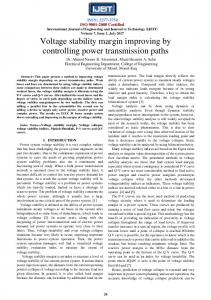
explained more in depth using the illustrative examples in the following section. IV. SIMULATION RESULTS New England 39-bus system is used to evaluate the effectiveness of the proposed centralized/decentralized optimizations for max.ERPR. The one line diagram of the system is represented in Fig. 1 and its description and data can be found in [16]. The voltage deviation of all buses is acceptable within of the nominal voltage. This system is partitioned into three areas, namely area , and . The areas are selected such that at least one border bus (bus 4 and 14) is connected to more than one interconnection line and one border bus (bus 39) is connected to a generator with the complementarity constraints. This particular system allows verifying the presented general formulation when
there are the complementarity constraints at the border buses as well as different number of the complicating variables and coupling constraints. In order to obtain more general conclusions, simulation results provided in this section are carried out for two loading levels namely; low and high loading levels. The total amount of active and reactive power loads at the low loading level are 6110 MW and 1594 MVAR, respectively. The loading of the system at the high loading level is assumed 15% more than the low loading level ( MW MVAR). Furthermore, the effect of the generators with the complementarity constraints at the border buses is investigated more in depth. The proposed OPF models are nonlinear optimization problems that are solved using “fmincon” with interior-point algorithm in MATLAB R2011b. In the presented results the horizontal
(8a) (8b) (8c) (8d) (8e) (8f) (8g) (8h)
(8i)
(8j)
(8k) (8l) (8m)
ALIZADEH MOUSAVI AND CHERKAOUI: MAXIMUM VOLTAGE STABILITY MARGIN PROBLEM
2999
Fig. 2. The max.ERPR for New England 39-bus system at the high loading level for the centralized with CC and without CC and for the decentralized without CC. Fig. 1. New England 39-bus system with 3 areas.
axis demonstrates the numbers of iterations since the decentralized approaches are iterative. Note that in the presented simulation results the abbreviation CC stands for the Complementarity Constraints. In the first study case, the effect of the CC on the value of objective function is studied. For this purpose, the presented formulations for the centralized and decentralized max.ERPR are
solved using (5) and (8), respectively. In order to deactivate the CCs, the value of is assumed equal to zero. Fig. 2 demonstrates the simulation results at the high loading level for the centralized with CC and without CC and for the decentralized without CC. This figure shows that the centralized and decentralized optimizations without CC converge to the same objective value. Also the consideration of the CCs increases the value of the objective function for the centralized optimization. Therefore, it is important to model these constraints to correctly repre-
(8n) (8o) (8p) (8q) (8r) (8s) (8t) (8u)
(8v)
(8w)
(8x)
(8y) (8z)
3000
Fig. 3. The max.ERPR for New England 39-bus system at the high loading level for the centralized with CC and for the decentralized with CC regardless of the proposed modifications.
Fig. 4. The max.ERPR for New England 39-bus system at the high loading level for the centralized with CC and for the decentralized with CC regardless of the proposed modifications.
sent the generators capability at the collapse point. It is expected that the CCs improves the results of the decentralized optimization similarly. Fig. 3 shows the results at the high loading level for the centralized optimization with CC using (5) and also for the decentralized optimization using (8) while the proposed modification for the CC are disregarded. These modifications result mainly from the added variables for the voltage of PV generators at the border buses of neighboring areas. As a result, the modified formulation includes: 1) the fifth term of the third part of the objective function in (8a); 2) the power flow equations at the border buses with PV generators given by (8v)–(8w) and (8h)–(8i); and 3) the extra constraint given by (8z) to guarantee the equality of the additional variable. Regardless of these proposed modifications, the objective function value becomes oscillatory as shown in Fig. 3. It is due to the fact that in this case study, there is a PV generator {G10} at border bus 39. In order to further investigate this issue, the generator {G10} is assumed as a PQ generator. The simulation results for the centralized and decentralized optimizations for the case with 9 PV generators and 1 PQ generator with CC and regardless to the proposed modifications in the formulation, is shown in Fig. 4. In
IEEE TRANSACTIONS ON POWER SYSTEMS, VOL. 29, NO. 6, NOVEMBER 2014
Fig. 5. The max.ERPR for New England 39-bus system at the high/low loading levels for the centralized with CC and for the decentralized with CC using the proposed modifications.
this case, the objective value of the decentralized optimization converges to the objective value of the centralized optimization since the PQ generator at the border bus does not have the CCs. This observation again confirms that the oscillatory behavior in Fig. 3 is originated from the CCs of PV generator in the border bus. In addition, it is worth mentioning that the values of the objective function in the case of 9PV and 1PQ generators is lower than the case of 10PV generators because in the first case the number of voltage control generators is lower than the latter case. Here, the simulation results for the low loading level are not presented. The behaviors similar to the presented results in Figs. 2–4 are observed for the decentralized optimization at the low loading level. As a result, the formulation of the decentralized optimization needs additional considerations whenever there is a PV generator at a border bus. The required modifications are necessary due to the presence of the CCs at the border bus. The further coordination is proposed in the presented formulation in (8). The simulation results for the centralized and decentralized optimizations with CC at the low/high loading levels are presented in Fig. 5. The presented results for the decentralized optimization benefit from the proposed formulation in (8). Although a small sub-optimality (1.3%–1.4%) is observed in the results of the decentralized approach, the objective value is not oscillatory anymore, like in Fig. 3. Therefore, the proposed modifications in the formulation of the decentralized optimization according to (8) are quite effective whenever there is a PV generator with CC at a border bus. Finally, it is worth mentioning that the value of the objective function at the optimum is higher in the case of the low loading level rather than the case of the high loading level since in the high loading level the system reaches its operating limits. The generators’ voltage set point and their reactive power output at the operating and collapse points for the low and high loading levels are reported in Tables I and II, respectively. These tables show the voltage of generators, the reactive power output of generators at the current operating point and at the collapse point, and ERPR of generators. The last columns of tables demonstrate the sum of the generators reactive power
ALIZADEH MOUSAVI AND CHERKAOUI: MAXIMUM VOLTAGE STABILITY MARGIN PROBLEM
3001
TABLE I VALUE OF CONTROL VARIABLES AND GENERATORS REACTIVE POWER OUTPUT FOR NEW ENGLAND 39-BUS SYSTEM IN LOW LOADING LEVEL
TABLE II VALUE OF CONTROL VARIABLES AND GENERATORS REACTIVE POWER OUTPUT FOR NEW ENGLAND 39-BUS SYSTEM IN HIGH LOADING LEVEL
output as well as their ERPR. It can be observed that the total reactive power output of generators at the current operating point is 2%–4% lower, than in the cases of centralized optimization. In addition, the total generators reactive power output at the collapse point is 0.4%–0.5% higher in the cases of centralized optimization. As a result, the before-mentioned small sub-optimality of the decentralized approach for ERPR can be demonstrated once more. Moreover, the obtained solutions for the control variables (here the voltage of generators) are given in bold in Tables I and II. These control variables are generally similar for both centralized and decentralized approaches. The only exception is the voltage of G10 at high loading level which is a little bit different in the decentralized approach in comparison to the centralized approach (1.0912 pu in the centralized and 1.1000 pu in the decentralized). That is the reason why the higher sub-optimality is observed in the case of high loading level (73.89 MVAR) than in the case of low loading level (56.19 MVAR). It should be mentioned that in the proposed formulation for the decentralized optimization, every area exchange with its neighboring areas the voltage magnitudes and angles at border buses as well as the Lagrangian multipliers related to the active and reactive power flows at the border buses. This information exchange should be carried out for both of the current operating and collapse points. In addition, for the areas whose border buses are connected to PV generators, the Lagrangian multipliers associated to the complementarity constraints of the generators, given by (8q), should be exchanged with the neighboring areas. V. CONCLUSIONS The multi-area voltage and reactive power management regarding the voltage stability is studied in this paper. The
maximization of effective reactive power reserve is considered as the optimization criterion. This optimization is studied using the centralized and decentralized approaches in the context of multi-area power systems. The proposed formulations take into account: 1) the generators reactive power limits; 2) the distributed slack bus model for the compensation of active power losses; and 3) the model of the generator switch between the constant terminal voltage and the constant reactive power output using complementarity constraints. The simulation results demonstrated that the traditional decentralized approach does not converge whenever there are PV generators at border buses. It is illustrated that this problem occurs due to the consideration of the complementarity constraints. Additional modifications are proposed for the formulation of the decentralized optimization in order to consider the effect of the complementarity constraints at border buses. The presented results demonstrated the effectiveness of the proposed formulation to handle such optimization problems. ACKNOWLEDGMENT The authors would like to thank Swiss Electric Research as the results reported in this paper have been carried out within the framework of the research project “Security of Multi-Area Power Systems (MARS)”. REFERENCES [1] O. Alizadeh Mousavi and R. Cherkaoui, Literature Survey on Fundamental Issues of Voltage and Reactive Power Control, 2011 [Online]. Available: http://mars.ethz.ch/en/researh-and-publications/publications.html [2] A. Zhang, H. Li, F. Liu, and H. Yang, “A coordinated voltage/reactive power control method for multi-TSO power systems,” Int. J. Electr. Power Energy Syst., vol. 43, pp. 20–28, 2012.
3002
[3] Y. Phulpin, M. Begovic, and D. Ernst, “Coordination of voltage control in a power system operated by multiple transmission utilities,” in Proc. IREP Symp., Buzios, Brazil, 2010. [4] Y. Phulpin, “Coordination of reactive power scheduling in a multi-area power system operated by independent utilities,” Ph.D. dissertation, Georgia Inst. Technol., Atlanta, GA, USA, 2009. [5] Y. Phulpin, M. Begovic, M. Petit, and D. Ernst, “A fair method for centralized optimization of multi TSO power system,” Int. J. Electr. Power Energy Syst., vol. 31, pp. 482–488, 2009. [6] Y. Phulpin, M. Begovic, M. Petit, and D. Ernst, “On the fairness of centralized decision making strategies in multi TSO power systems,” in Proc. Power Syst. Comput. Conf., Glasgow, U.K., 2008. [7] Y. Phulpin, M. Begovic, and M. Petit, “External Network modeling for MVAr scheduling in multi area power systems,” in Proc. PowerTech, Lausanne, Switzerland, 2007. [8] Y. Phulpin, M. Begovic, M. Petit, J. B. Heyberger, and D. Ernst, “Evaluation of network equivalents for voltage optimization in multi-area power systems,” IEEE Trans. Power Syst., vol. 24, no. 2, pp. 729–743, May 2009. [9] Y. Phulpin, M. Begovic, M. Petit, and D. Ernst, “Decentralized reactive power dispatch for a time varying multi TSO system,” in Proc. Hawaii Int. Conf. Syst. Sci., 2009. [10] G. Hug-Glanzmann and G. Andersson, “Decentralized optimal power flow control for overlapping areas in power systems,” IEEE Trans. Power Syst., vol. 24, no. 1, pp. 327–336, Feb. 2009. [11] M. Arnold, S. Knopfli, and G. Andersson, “Improvement of OPF decomposition methods applied to multi-area power systems,” in Proc. PowerTech, Lausanne, Switzerland, 2007. [12] M. Granada, M. J. Rider, J. Mantovani, and M. Shahidehpour, “A decentralized approach for optimal reactive power dispatch using a Lagrangian decomposition method,” Electr. Pow. Syst. Res., vol. 89, pp. 148–156, 2012. [13] W. Yan, L. Wen, W. Li, C. Y. Chung, and K. P. Wong, “Decomposition–coordination interior point method and its application to multiarea optimal reactive power flow,” Int. J. Electr. Power Energy Syst., vol. 33, pp. 55–60, 2011. [14] O. Alizadeh Mousavi and R. Cherkaoui, “On the inter-area optimal voltage and reactive power control,” Electr. Power Energy Syst., vol. 52, pp. 1–13, 2013. [15] W. Rosehart, C. Roman, and A. Schellenberg, “Optimal power flow with complementarity constraints,” IEEE Trans. Power Syst., vol. 20, no. 2, pp. 843–822, May 2005. [16] O. Alizadeh Mousavi, M. Bozorg, and R. Cherkaoui, “Preventive reactive power management for improving voltage stability margin,” Electr. Pow. Syst. Res., vol. 96, pp. 36–46, 2013. [17] I. El-Samahy, K. Bhattacharya, C. Canizares, M. Anjos, and P. Jiuping, “A procurement market model for reactive power services considering system security,” IEEE Trans. Power Syst., vol. 23, no. 1, pp. 137–149, Feb. 2008.
IEEE TRANSACTIONS ON POWER SYSTEMS, VOL. 29, NO. 6, NOVEMBER 2014
[18] A. G. Expósito, J. L. M. Ramos, and J. R. Santos, “Slack bus selection to minimize the system power imbalance in load-flow studies,” IEEE Trans. Power Syst., vol. 19, no. 2, pp. 987–995, May 2004. [19] R. Natarajan, Computer-Aided Power System Analysis. New York, NY, USA: Marcel Dekker, 2002. [20] D. Feng, B. H. Chowdhury, M. L. Crow, and L. Acar, “Improving voltage stability by reactive power reserve management,” IEEE Trans. Power Syst., vol. 20, no. 1, pp. 338–345, Feb. 2005. [21] B. Tamimi, C. A. Canizares, and S. Vaez-Zadeh, “Effect of reactive power limit modeling on maximum system loading and active and reactive power markets,” IEEE Trans. Power Syst., vol. 25, no. 2, pp. 1106–1116, May 2010. [22] A. Efthymiadis and Y. Guo, “Generator reactive power limits and voltage stability,” in Proc. 4th Int. Conf. Power System Control and Manage., London, U.K., 1996. [23] F. Capitanescu, “Assessing reactive power reserves with respect to operating constraints and voltage stability,” IEEE Trans. Power Syst., vol. 26, no. 4, pp. 2224–2234, Nov. 2011. [24] P. Biskas and A. Bakirtzis, “Decentralised OPF of large multiarea power systems,” IEE Proc. Gener. Transm. Distrib., vol. 153, pp. 99–105, 2006. [25] A. Marinakis, M. Glavic, and T. Van Cutsem, “Control of phase shifting transformers by multiple transmission system operators,” in Proc. PowerTech, Lausanne, Switzerland, 2007.
Omid Alizadeh Mousavi (S’14) received the B.Sc. and M.Sc. degrees in electrical engineering, from Fredowsi University of Mashhad and Amirkair University of Technology in 2006 and 2009, respectively. Currently, he is pursuing the Ph.D. degree at EPFL, Lausanne, Switzerland. His research interests are power system risk and security assessment and stability analysis.
Rachid Cherkaoui (SM’10) received the M.S. degree in electrical engineering and the Ph.D. degree from EPFL, Lausanne, Switzerland, in 1983 and 1992, respectively. From 1993 to 2009, he was leading the research activities in the field of optimization and simulation techniques applied to electrical power and distribution systems. Since 2009, as senior scientist, he is the head of the power system group at EPFL. Presently, the main research topics of his group are concentrated on electricity market deregulation, distributed generation and storage, and power system vulnerability mitigation. He is a member of technical program committees of various conferences. He was a member of CIGRE task forces C5–2 and working group C5–7 related to electricity market deregulation, and IEEE Swiss Chapter officer.