75 Kallipoleos Street, P.O.Box.20537, CY-1678 Nicosia, Cyprus. {cs98cc2 ... Dedicated Resources and the handover decision making was based on a ...
MBMS Handover Control for Efficient Multicasting in IPBased 3G Mobile Networks Christopher Christophorou and Andreas Pitsillides Department of Computer Science University of Cyprus 75 Kallipoleos Street, P.O.Box.20537, CY-1678 Nicosia, Cyprus {cs98cc2 & Andreas.Pitsillides}@ucy.ac.cy Abstract – Handover Control aims to provide continuity of mobile services to a user traveling over cell boundaries in a cellular infrastructure. So far Handover Control have been considered only between cells supporting the service on Dedicated Resources and the handover decision making was based on a comparison between an observed value and a predetermined threshold chosen in a manner so as to maximize the overall system capacity. Now with the introduction of Multimedia Broadcast Multicast Service (MBMS), for radio efficiency reasons, one cell can use either Common or Dedicated resources for the distribution of the same content in a Cell. Thus the mobile users that are on the move may have to deal with dynamic changes of network resources when crossing the cell edge, introducing new types of handovers (MBMS Handovers). Using the current Handover Algorithm when an MBMS Handover is executing will not be so efficient. For the efficient execution of these new types of handovers new parameters have to be considered and a different approach has to be followed. This paper proposes a new Handover Algorithm which efficiently maximizes the overall system capacity when mobile MBMS users have to deal with these new types of handovers.
I. INTRODUCTION Initially, the need for the mobile phones to support a variety of multimedia mobile services at high data rates has led to the definition of 3rd Generation (3G) Mobile Networks (standardized in Europe as UMTS [1] - Universal Mobile Telecommunications System) and the choice of Wideband Code Division Multiple Access (WCDMA) [2] for the radio resource allocation. A consequence of using WCDMA is that capacity of 3G systems is not hard limited. This means that an additional user entering the system cannot be blocked because of the limited amount of available channels. If a sufficient number of spreading codes is available, the noise rise (interference) due to increased load will be the main capacitylimiting factor in the network. At first, UMTS offered tele-services (e.g. Voice and SMS) and Bearer Services for Point-to-Point transmission using the Unicast technology. Later, with the introduction of technologies such as, IP Video Conferencing, Streaming Video and others, there was an increasing need for communication between one sender and many receivers, leading to the need of Point-to-Multipoint transmission. One efficient way to implement this type of transmission is the use of broadcast and multicast technologies [3]. To provide broadcast and multicast type of data transmission in UMTS,
the 3GPP (3rd Generation Partnership Program) proposed some enhancements on the UMTS Release-6 architecture that led to the definition of Multimedia Broadcast Multicast Service (MBMS) system [4]. MBMS is a Point-to-Multipoint service in which data is transmitted from a single source entity to multiple recipients, allowing the network resources to be shared. Moreover, with the introduction of MBMS Services in UMTS Networks, the Radio Network Controller (RNC), for radio efficiency reasons (See Section II) can use either Dedicated resources (one Dedicated Channel (DCH) for each User Equipment (UE) in the Cell) or Common resources (one Forward Access Channel (FACH) shared by all the UEs in a Cell) to distribute the same content in a Cell. Thus the mobile users that are on the move and receive an MBMS Service may have to deal with dynamic changes of network resources (from Common to Dedicated and vice versa) when crossing the cell edge introducing new types of Handovers (MBMS Handovers). So far Handover Control have been considered only between cells supporting the service on Dedicated Resources and the handover decision making was based on a comparison between an observed value and a predetermined threshold chosen in a manner so as to maximize the overall system capacity. Using this handover approach when the mobile users have to deal with the new types of MBMS Handovers will not be so efficient. In order to achieve maximization of the overall system capacity a different approach has to be followed. This paper proposes a new handover algorithm which efficiently achieves increased cell capacity when the mobile users have to deal with these new types of MBMS handovers. The key of accomplishing this capacity achievement is the full utilization of the broadcast nature of Common resources. The paper is organized as follows: Section II makes a comparison between the Dedicated and Common use of resources. Section III makes a brief introduction on the current Handover Algorithm followed by the description of the Proposed MBMS Handover Algorithm. The Performance Evaluation is made in Section IV. Finally the paper provides a conclusion on the proposed MBMS Handover Algorithm presented. I. COMMON VS DEDICATED USE OF RESOURCES The main difference with the Dedicated and Common resources is that FACH does not allow the use of fast power
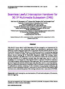
control or no power control at all. Fast power control is the most important aspect in WCDMA because it optimizes the radio transmission power. Despite this limitation, some other benefits can be obtained from the utilization of Common Resources. In order to illustrate these benefits the following scenario shown in Fig. 1 has been simulated. Fig. 4 Traffic Received - Common Vs Dedicated Resources (bytes/sec)
Fig. 1 Common Vs Dedicated Use of Resources Scenario
In this scenario, UE 1 in Cell 1 and UE 2 in Cell 2 follow exactly the same trajectory and receiving the same MBMS Streaming Video of 8 Kbytes/second. The coverage of the cells is 1 Km and the pathloss model used is “Pedestrian Outdoor”. Cell 1 uses Dedicated Resources (Point-to-Point Cell) while Cell 2 uses Common Resources (Point-toMultipoint Cell) to distribute the same MBMS Service content. Three instances of the same scenario (Low, Medium & High load) have been simulated using different number of users in each Cell at different positions. In Fig. 2 the distance of UE 1 and UE 2 from their attached Base Station during the simulation time is illustrated. As they follow the same trajectory and start at equal distances from the Base Stations their distance from their attached Base Station will be the same during simulation time.
From the results shown above (Fig. 2 – Fig. 4) the following remarks have been observed: • Radio Efficiency Reason: As a Common Channel (FACH) needs to be received by all the UEs in the Cell, also those near the Cell’s border, it requires more radio resources (power) than a DCH. Therefore, few DCHs might outperform one Common Channel in terms of radio resource efficiency, whenever the users are ‘few’ and located ‘near’ the BS (See Instance 1 & 2). On the other hand, if the number of users is increasing it is more efficient to use a Common Channel (Instance 3). • The Total Downlink Transmission Power allocated for Common resources (FACH) is fixed and at a level aimed to ensure the QoS level requested throughout the Coverage of the Point to Multipoint Cell despite the number and the location of the Users in the Cell. • The Total Downlink Transmission Power allocated for Dedicated Resources (DCH) is variable and increasing exponentially while the User Equipment (UE) distance from the Base Station is increasing. Also, the more the UEs in the Cell thus the higher the interference, the more exponential the increase in the total power required.
Fig. 2 UE 1 and UE 2 distance from their attached Base Station
Results concerning the QoS level of the received signal (Traffic Received) and the capacity used (Total Downlink Transmitted Carrier Power) from each Cell have been collected for each instance and presented below.
Fig. 3 Downlink Transmitted Carrier Power used - Common Vs Dedicated Resources (watts)
Fig. 5 Taking full advantage of Common Resources Broadcast Nature
By taking into consideration the observations made above, in order to maximize the overall system capacity during an MBMS handover (minimize the total downlink power used), while at the same time satisfy the requested QoS level, the handover should be executed as close as possible to the Base Station in the Point-to-Point Cell (Point-to-Point Base Station) but not outside of the Point-to-Multipoint Cell Coverage (switching channels outside of the Point-to-Multipoint Cell Coverage would degrade the quality of the received signal). Thus the proper place to switch channels is on the Border of the Point-to-Multipoint Cell (See Fig. 5). Since it is very difficult to achieve such accuracy, when we say “On the Border” we will mean at distance equal with Coverage of Poin- to-Multipoint Cell ± 5 meters (error margin) from the Base Station in the Point-to-Multipoint Cell (Point-toMultipoint Base Station). III. HANDOVER CONTROL
A. Current Handover Algorithm [5] In view of the fact that macrodiversity (Soft Handover) is not allowed between different kinds of resources Soft Handover cannot be utilized. Therefore the new MBMS Handover types will be deal as Hard Handover cases. The current Hard Handover Algorithm is fairly simple; the mobile station performs a handover when the Common Pilot Channel (CPICH) signal strength of a neighboring cell exceeds the CPICH signal strength of the current cell with a predefined threshold (See Fig 6).
only the CPICH signal strength of the Point-to-Multipoint Base Station. When the measured CPICH signal strength becomes equal with the “MBMS Replacement Threshold” the MBMS Handover will be triggered. Accurate measurements of the CPICH signal strength received from the Point-to-Multipoint Base Station form the main input making handover decisions. Measurement errors can lead to unnecessary handovers. Therefore, it is important to apply filtering on the handover measurements to average out the effect of fast fading. 1) Estimating the distance D As said above, according to the type of MBMS Handover that is executing, the estimation of the distance D will differ. Let us suppose that we want to estimate the distance D when the UE is moving from a Point-to-Point Cell towards a Pointto-Multipoint Cell (Fig. 7).
Fig. 6 Current Hard Handover algorithm
B. Proposed MBMS Handover Algorithm Before starting the in-depth analysis of the Proposed MBMS Handover Algorithm it worth to mention that for simplicity reasons we will assume that the UE is on Line of Sight (LOS) with the Point-to-Multipoint Base Station and the Coverage of the Point-to-Multipoint cells are presented as homogeneous circles. As we have seen in Section II, when an MBMS Handover is performing, the best position to execute the handover (switch channels) is on the border of the Point-to-Multipoint Cell. Since it is difficult to achieve this using the current Hard Handover Algorithm (due to the approach used), a different approach has to be followed. The Proposed MBMS Handover Algorithm aims to minimize the interference caused in the Point-to-Point Cells by executing the MBMS Handover “on the border of the Point-to-Multipoint cell”. Since some delay is caused from the time the handover is triggered until the UE switches channels (Handover Delay), in order for switching channels “on the border” the handover should be triggered at some distance (Safety Distance) before the UE enters or leaves the Coverage of the Point-to-Multipoint Cell. Therefore, in order to take full advantage of Common Resources, the MBMS Handover should be triggered close to the border of the Point-toMultipoint Cell at distance D equal to the Coverage of the Point-to-Multipoint Cell ± Safety Distance from the Point-toMultipoint Base Station. The “±” sign means that according to the type of MBMS Handover the safety distance will be added or subtracted. After evaluating the distance D, this distance should be expressed at a value that the UE can measure during its mobility. Therefore this distance D will be expressed as the CPICH signal strength (dB) of the Point-toMultipoint Base Station that the UE should measure at the estimated distance D. We will refer to this value as the “MBMS Replacement Threshold”. Now while the UE is moving from one Cell to another will continuously measure
Fig. 7 Moving from Dedicated to Common Resources
Since the UE will measure only the CPICH of the Point-toMultipoint Base Station and the UE is currently located in the Point-to-Point Cell, the handover should be triggered at ∆t time (According to the Handover Delay time) before the UE enters the coverage of the Point-to-Multipoint Cell. This must happen in order for the channel switching to take place on the border of the Point-to-Multipoint Cell. Therefore, the Safety Distance should be added to the Coverage of the Point-toMultipoint Cell in order to estimate the distance D.
Fig. 8 Moving from Common to Dedicated Resources
On the other hand, if the UE is moving from a Point-toMultipoint Cell towards a Point-to-Point Cell (Fig. 8), the handover should be triggered at ∆t time before the UE leaves the Coverage of the Point-to-Multipoint Cell. Therefore, in this case, the Safety Distance should be subtracted (-). The Coverage of the Point-to-Multipoint Cell and the Handover Delay (∆t time) might vary. Thus the task of evaluating these parameters will be given to the RNC. The RNC should periodically estimate these parameters and broadcast them to the UEs in the Cell through the MBMS Point-to-Multipoint Control Channel (MCCH) [4]. Due to the fact that the MCCH currently does not include these fields, it should be enhanced in order to add two more fields for the accommodation of these two new parameters. 2) Estimating the Safety distance
The Safety Distance is variable and will be estimated by the UE during its mobility. In order to estimate the Safety Distance, the Handover Delay (∆t), the Speed and the Direction of the UE are going to be considered. The direction of the UE will be expressed as the angle φ that is created between the straight line that connects the UE with the Pointto-Multipoint Base Station and the line showing the direction of the UE. According to the type of MBMS Handover that is executing, a different approach will be used in order to estimate the Safety Distance. Lets first describe the case where the UE is moving from a Point-to-Point Cell towards the Point-to-Multipoint Cell (Fig. 9). If the UE is moving with some Speed and the Handover Delay is equal to ∆t, then the UE will switch channels after it covers a ∆t x Speed distance from the time the Handover is triggered. This is also the maximum value that the Safety Distance can take. Since the Speed of the mobile user and the Handover Delay (∆t) caused are variable parameters the maximum Safety Distance will vary while the mobile user is moving. Therefore the maximum Safety Distance should be continually estimated by the UE during its mobility.
Fig. 9 UE moving from a Point-to-Point towards a Point-to-Multipoint Cell
Now while the UE is moving towards the Point-toMultipoint Cell, it will continually estimate the Initial “MBMS Replacement Threshold” according to the Maximum Distance D and in parallel it will measure the CPICH signal strength of the Point-to-Multipoint Base Station. The Maximum Distance D will be equal with the Coverage of the Point-to-Multipoint Cell + maximum Safety Distance. When the measured CPICH signal strength becomes equal with the Initial “MBMS Replacement Threshold” the UE will be triggered to estimate its Direction (angle φ). If the angle φ is equal with 0o (Thus the UE is moving towards the Point-to-Multipoint Base Station), the Handover will be triggered immediately since the UE will reach the border after Speed x ∆t distance. On the other hand, if the estimated angle φ is not equal to 0o the handover should not be immediately triggered. In this case the UE will have to cover a distance equal to (Speed x ∆t) + ∆d until it reaches the border of the Point-to-Multipoint Cell. Since the UE will switch channels after a Speed x ∆t distance, if the handover is triggered, the channel switching will be perform at ∆d distance outside of the Point-to-Multipoint Cell
coverage, resulting in a degradation on the quality of the received signal. So the UE will have to cover a ∆d distance first before triggering the handover. Therefore a new Safety Distance should be estimated, taking into consideration not only the Speed of the UE and the Handover Delay (∆t time), but also the UE’s Direction in order for a new MBMS Replacement Threshold to be estimated. When the measured CPICH signal strength becomes equal with the new MBMS Replacement Threshold then the handover will be triggered. The formula used to estimate the new Safety Distance when the UE is moving from a Point-to-Point towards a Point-toMultipoint cell is executing is shown in (1): 2 (1) Safety _ D = ∆d 2 + (Cov + a ) − 2 × ∆d × (Cov + a ) × cosϕ − Cov ⎤ ⎡ ⎞ ⎛ Cov + a Cov × sin ⎢arcsin⎜ × sin ϕ ⎟ − ϕ ⎥ Cov ⎠ ⎝ ⎦ −a ⎣ ∆d = sin ϕ
& Cov = Coverage_ Of _ PtM _ Cell The case where the UE is moving from a Point-toMultipoint Cell towards a Point-to-Point Cell (Fig. 10) will follow more or less the same approach. What is different here is the formula that will be used in order to estimate the new Safety Distance. The formula is shown in (2). a = ∆t × Speed
Fig. 10 UE moving from a Point-to-Multipoint towards a Point-to-Point Cell Safety _ D = Cov − ∆d 2 + (Cov − a ) + 2 × ∆d × (Cov − a ) × cosϕ 2
2)
⎡ ⎛ Cov − a ⎞⎤ × sin ϕ ⎟⎥ Cov × sin ⎢ϕ − arcsin⎜ Cov ⎝ ⎠⎦ ⎣ ∆d = −a sin ϕ
a = ∆t × Speed
& Cov = Coverage_ Of _ PtM _ Cell
3) Estimating MBMS Replacement Threshold As we have said above, after evaluating the distance D, this distance should be expressed at a value that the UE can measure during its mobility. In order to estimate this value, the pathloss between the UE and the Point-to-Multipoint Base Station has to be considered. The pathloss can be estimated using the propagation model of the Cell environment [6] defined by the International Telecommunications Union (ITU). For example, for a Pedestrian Outdoor propagation model, the pathloss is estimated using the formula shown in (3). Where R is the distance between the UE and Base Station in Km and freq is the Carrier frequency in MHz. Pathloss = 40 × log10 R + 30 × log10 freq + 49 (3)
For freq equal with 2000 MHz used for UMTS band application and for R equal with the estimated distance D, the formula becomes as shown in (4): Pathloss = 40 × log10 D + 148 (4) By estimating the pathloss and by taking into consideration some other parameters we can estimate the CPICH power (watts) that the UE should receive at distance D (rcv_power). By taking into consideration the total downlink interference caused by other Node_Bs (inoise) and the in-band noise caused from background and thermal sources (rx_bkgnoise) the “MBMS Replacement threshold” will be equal with the value (dB) that is given by the formula shown in (5). ⎞ ⎛ rcvd _ power (5) ⎟ RT _ E / N = 10 × log ⎜
Point Cell is minimized from 1.166 watts to 0.9 watts (23% decrease), without affecting the QoS level requested for the MBMS Service. Moreover, the radio resources in the Point-toPoint Cell are released 34 seconds sooner, making space for new admissions in the Point-to-Point Cell. Results concerning the QoS level of the received signal and the capacity used (Total Downlink Transmitted Carrier Power) have been obtained for Scenario 2 and presented below:
IV. PERFORMANCE EVALUATION
Fig. 13 Total Downlink transmitted power used (watts) & Traffic Received (bits/sec) – Scenario 2
c
o
10
⎜ inoise + rx _ bkgnoise ⎟ ⎠ ⎝
For the performance evaluation of the proposed scheme OPNET Modeller 11.0.A [7] was used. The performance of the proposed MBMS Handover Algorithm was evaluated by comparing the amount of the total downlink power that becomes available when the proposed scheme is used compared to the current Handover Algorithm. Having seen that the power used for Common Resources is not affected by the number or the position of the UEs in the Cell, the evaluation will be focused on the Point-to-Point Cells. A series of 4 scenarios will be used in order to collect the required results concerning the feasibility and the performance evaluation of the proposed scheme. Scenario 1 (Fig. 11) considers the case where UE 1 is moving from a Point-to-Point Cell (Dedicated Resources) towards a Point-to-Multipoint Cell (Common Resources) while Scenario 2 (Fig. 11) considers the vice versa case. All the UEs in the Point-to-Point Cell are mobile and receiving an MBMS Streaming Video of 64 Kbits/second.
As it is shown in Fig. 13, when the Proposed Algorithm is used, the maximum Downlink Power required in the Point-toPoint Cell is minimized from 1.76 watts to 1.06 watts (40% decrease), without affecting the QoS level requested for the MBMS Service. Moreover, the radio resources in the Point-toPoint Cell are allocated 30 seconds later, thus not causing additional interference in the Point-to-Point Cell during this period. Scenario 3 (Fig. 14) considers the case where a group of five UEs are moving from a Point-to-Point Cell towards a Pointto-Multipoint Cell while at the same time a group of two UEs are following the vice versa direction. All the UEs are receiving an MBMS Streaming Video of 25 Kbits/second and the Cell pathloss model used is “Pedestrian Outdoor”.
Fig. 14 Scenario 3 Fig. 11 Scenario 1 & Scenario 2
Results concerning the QoS level of the received signal and the capacity used (Total Downlink Transmitted Carrier Power) have been obtained for Scenario 1 and presented below:
Fig. 12 Total Downlink transmitted power used (watts) & Traffic Received (bits/sec) – Scenario 1
As it is shown in Fig. 12, when the Proposed Algorithm is used, the maximum Downlink Power required in the Point-to-
Results concerning the capacity used (Total Downlink Transmitted Carrier Power) when the Proposed and the Current Handover Algorithms are used have been obtained and presented below:
Fig. 15 Total Downlink transmitted power used (watts) – Scenario 1: Current Vs Proposed Handover Algorithm
As it is shown in Fig. 15, when the Proposed Algorithm is used, a great decrease on the total power used was observed.
This gain was caused due to ability of the Proposed MBMS Handover Algorithm to execute the handover on the Border of the Point-to-Multipoint Cell. By doing that, the interference caused in the Point-to-Point Cell will be reduced and less power consumption will be required for the UEs. This will release the Base Station power for servicing more users, resulting in the enhancement of the overall system capacity by also maintaining a satisfactory call quality. Scenario 4 (Fig. 16) is exactly the same as Scenario 3, but in this scenario, UE 6 & UE 7 before leaving the coverage of the Point-to-Multipoint Cell, at about 980 meters from the Pointto-Multipoint Base Station, change their direction starting moving as shown below.
Fig. 16 Scenario 4
Results concerning the capacity used (Total Downlink Transmitted carrier Power) when the Proposed and the Current Handover Algorithms are used have been obtained and presented below:
service using the FACH Channel transmitted from the Point to Multipoint Base Station. In all Scenarios presented, by using the Proposed MBMS Handover Algorithm when an MBMS Handover is performing, a great decrease on the total power used was observed. This gain was caused due to ability of proposed algorithm to execute the handover as close to the Point to Point Cell, thus minimizing the maximum downlink power required, at a position where requested QoS level of MBMS Service could also be satisfied and also to its ability to prevent unnecessary handovers. Moreover, by using the Proposed Algorithm when the UE was moving from a Point-to-Point Cell towards a Point-to-Multipoint Cell, the dedicated resources in the Pointto-Point Cell were released as soon as possible thus making space for new admissions. Also, by using the Proposed Algorithm when the UE was moving from a Point-toMultipoint Cell towards a Point-to-Point Cell, the dedicated resources were allocated only when necessary thus not causing additional interference in the Cell. Using less power means that less interference is caused in the Point-to-Point Cells. As we have seen in the results presented, using the Proposed MBMS Handover Algorithm when the mobile users have to deal with MBMS Handovers it can yield considerable benefits. Since WCDMA is interference-limited this will reflect to an increase on the overall system capacity. V. CONCLUSIONS
Fig. 17 Total Downlink transmitted power used (watts) – Scenario 4: Current Vs Proposed Handover Algorithm
As it is shown in Fig. 17, when the Proposed Algorithm is used, a great decrease on the total power used was observed (up to 80% decrease on the total Downlink Power used). This gain was caused for two reasons. The first is as we have seen also in Scenario 3, the ability of the Proposed MBMS Handover Algorithm to execute the handover on the border of the Point to Multipoint Cell thus reducing the interference caused in the Point-to-Point Cell and achieving less power consumption for the UEs. The second is the ability of the Proposed MBMS Handover Algorithm to prevent unnecessary handovers from happening. For example, when the Proposed Handover Algorithm is used, UE 6 and UE 7 are not handover into the Point-to-Point Cell even though the UEs are near the Border of the Point-to-Multipoint Cell, since the UEs can still receive the MBMS Service with the requested QoS from the FACH transmitted from the Point-to-Multipoint Base Station. Therefore the demanded capacity in the Point to Point Cell will not be increased since the UEs instead of handover into the Point to Point Cell will continue receiving the MBMS
In this paper, a new MBMS Handover Algorithm is proposed that deals with the new aspects of handover introduced with MBMS. The main idea of the proposed scheme is to minimize the interference caused in the Point-toPoint Cells, by taking full advantage of the Common Resources broadcast nature. We show that the proposed algorithm achieves enhanced Cell capacity in Point-to-Point Cells while it does not affect the Point-to-Multipoint Cells. This capacity achievement occurs only when the UE moves from Dedicated to Common Resources and vice versa. In wireless/mobile environments where the radio resources are limited, any capacity increase is of major importance therefore the achievement of the proposed algorithm is crucial for the MBMS system. ACKNOWLEDGMENT This work is partially supported by IST-2003-507607 BBONE: Broadcasting and Multicasting Over Enhanced UMTS Mobile Broadband Networks project. The authors also thank OPNET Technologies Inc. for providing software licence to carry out the simulations of this research. REFERENCES [1] Heikki Kaaramen, Ari Ahtiainen, Lauri Laitinen, Siamak Naghian, Valtteri Niemi. “UMTS Networks - Architecture, Mobility, and Services”. Jhon Wiley & Suns Ltd, England, 2001. [2] H. Holma, A. Toskala, “WCDMA for UMTS”, 3rd Edition, John Wiley and Sons Ltd, England, 2004
[3] Janne Aaltonen, Jouni Karvo, Samuli Aalto, “Multicasting vs. Unicasting in mobile communication systems”,International Workshop on Wireless Mobile Multimedia, 2002 [4] 3GPP TS 25.346 “Technical Specification Group Services and System Aspects; Introduction of the Multimedia Broadcast Multicast Service (MBMS) in the Radio Access Network (RAN); Stage 2” [5] 3GPP TR 25.922, “Technical Specification Group Services and System Aspects; Radio Resource Management Strategies” [6] Universal Mobile Telecommunications System (UMTS) TR 101 112 V3.2.0, “Selection procedures for the choice of radio transmission technologies of the UMTS (UMTS 30.03 version 3.2.0). [7] OPNET University Program: http://www.opnet.com/services/university/