Hindawi Publishing Corporation International Journal of Distributed Sensor Networks Volume 2013, Article ID 853014, 11 pages http://dx.doi.org/10.1155/2013/853014
Research Article MCNC: Data Aggregation and Dissemination in Vehicular Ad hoc Networks Using Multicast Network Coding Lingzhi Li,1 Shukui Zhang,1,2 Yanqin Zhu,1 and Zhe Yang1 1 2
School of Computer Science & Technology, Soochow University, Suzhou 215006, China State Key Laboratory for Novel Software Technology, Nanjing University, Nanjing 210093, China
Correspondence should be addressed to Shukui Zhang;
[email protected] Received 12 April 2013; Accepted 4 September 2013 Academic Editor: Liusheng Huang Copyright © 2013 Lingzhi Li et al. This is an open access article distributed under the Creative Commons Attribution License, which permits unrestricted use, distribution, and reproduction in any medium, provided the original work is properly cited. Nowadays, more and more APs are deployed for the wireless access. The roadside APs are able to improve the bandwidth of VANETs. In this paper, we design a Multicast Network Coding (MCNC) method to aggregate and disseminate data in VANETs. It is appropriate for the areas where APs have been deployed but cannot cover the all range of vehicles movement. Data transmission is divided into 3 stages in MCNC. Network coding, multicast aggregating, and decoding are implemented in the 3 stages, respectively. Simulation results show that MCNC is able to cut down 2/3 overhead messages of Epidemic when the cover area of the APs is only 1/5. Its loss rate and delay are lower than the other methods. We also discuss its benefit for the deployment of VANETs.
1. Introduction Vehicular networks are usually regarded as a class of adhoc networks, where mobile nodes are vehicles exchanging data with each other. Vehicle can communicate with nearby vehicles when their distance is less than the communication range. Data are delivered among vehicles via Vehicleto-Vehicle (V2V) protocol. Vehicular Ad hoc Networks (VANETs) will diverse applications associated with traffic safety [1], traffic efficiency [2], entertainment, file sharing [3, 4], and so on [5]. However, vehicles move at different speeds and form dynamic networks over time. VANET changes so fast; it is often difficult to find a path between a pair of vehicles using ordinary ad hoc routing protocol. Epidemic is the high reliability protocol, but it will waste too much bandwidth and reduce the scalability of networks [6]. Deploying infrastructures is a method to improve the reliability of data delivery. Intelligent VANET is a way of integrating on multiple wirelesses such as IEEE 802.11, 3G cellular systems, and IEEE 802.16e in vehicular networks [7]. Vehicles communicate with roadside infrastructures via Vehicle-to-Infrastructure (V2I) protocol. The infrastructures are connected via the wired networks and are able to buffer more data than vehicles. The experiments in [8] show that the
deployment of infrastructures can bring up to the improvement of performance in delivery ratio. With the increasing use of smart phones, 3G cellular systems become a popular infrastructure, but the research in [9] suggests that cellular data bandwidth is likely to remain limited and expensive. With the recent development of the IEEE 802.11p [10] 5.9G DSRC/WAVE radios, Wi-Fi based Access Points (APs) on the side of road will be more as the infrastructures of VANETs. Most applications of VANETs focus on planning vehicle paths, such as detecting remote road conditions [11]; sensing traffic lights [12]; avoiding rear collisions [10]. These applications require disseminating data to part of vehicles in some regions. The receivers are dynamic and cannot be identified by senders because of vehicles constant movement. It is impossible that infrastructures signal covers all of regions reached by vehicles. Multihop communications among vehicles are necessary to destinations or infrastructures. So routing packet remains to be a challenge in such network architecture which integrates V2V communication with V2I communication. However, vehicle movements are constrained to roads. Even though lots of vehicles are equipped with GPS receivers or smart phones to define their routes, their movements are probably constrained to preset paths. It is another characteristic of VANETs that it is possible to predict the vehicle movement [13].
2 In this paper, we present a Multicast Network Coding (MCNC) method to aggregate and disseminate data in VANETs. Data are divided into short fixed-size blocks in source vehicle and disseminated to the other vehicles. The vehicles nearby APs implement network coding and send the coding blocks to APs. The blocks are aggregated and recoded among APs multicast tree. Finally, the blocks are sent out in APs that the destinations are predicted to close. The experiments show that MCNC is able to reduce overhead messages and enhance the reliability of transmission. MCNC is designed according to the former characteristic of VANETs and appropriate for the areas that Wi-Fi based APs have been set up but cannot cover entirely. The remainder of this paper is organized as follows. In the next section, we discuss the related work. Section 3 presents the description and implementation of the MCNC. The evaluation and analysis of the MCNC are showed in Section 4. The paper is concluded in Section 5.
2. Related Works In recent years, many studies focus on deploying infrastructures in VANETs. It is proved [8] to bring up the improvement of data delivery. Cabernet [14] proposes onehop Internet access schemes using open Wi-Fi based APs in VANETs. In [15], Bychkovsk et al. analyze the feasibility that vehicles can access open Wi-Fi based APs providing the wired network connections in VANETs. They define the prime method of data delivery from APs to vehicles. Throwboxes [16] as infrastructures can hold packets and later forward the packets to other nodes. It helps relay messages between mobile clients in a Delay Tolerant Network (DTN) and saves power in scheduling sleep. MAR [17] as an infrastructure is a commuter router that exploits wireless diversity to provide improved data for users. It can be placed in moving vehicles to enable high-speed data access. DP [18] on the roadside is proposed to address the data dissemination in VANETs. Data poured from the source are buffered and rebroadcast at the intersections. It focuses on data dissemination, and no buffer allocation scheme is proposed. MobTorrent [19] is a framework designed for vehicles accessing to roadside WiFi APs. Vehicles inform the selected APs to fetch data. The scheduling algorithm in MobTorrent replicates the data on mobile helpers. A few studies have been attracted on utilizing vehicle trajectory information for VANETs of deploying APs. More and more vehicles are equipped with satellite navigation systems. With increasing usage of smart phones like Apple iPhone or Android phones, navigation systems based on smart phones are popular. Vehicle trajectory information has become a valuable input for data forwarding. In [20], a protocol is proposed to enable efficient multihop routing capabilities. It fully supports two-way communications between mobile vehicles and APs. Vehicular mobility is predicted on the information offered by the navigation system in terms of final destination and path. TSF [21] considers a reliable, efficient APs-to-vehicles data delivery by minimizing the packet delivery delay. Data delivery is performed through
International Journal of Distributed Sensor Networks the computation of a target point based on the destination vehicle’s trajectory information. Roadside APs can be selected as relays where destination vehicle is expected to pass by. Selecting AP optimally minimizes the packet delivery delay. TBD [22] utilizes vehicle trajectory information to improve communication delay and delivery probability for vehiclesto-APs destination communications. A delay model of packets routing along roads is set up. The path with minimum delay can be found with the help of the real-time traffic condition information. There is also some research leveraging roadside parking to distribute data in VANETs. ParkCast [23, 24] assumes that the parked vehicles are grouped into a line cluster at roadside. It defines the communication between moving vehicles and parked ones. The wireless device on vehicles has a battery for supporting the communication in parking. APs are replaced by parked vehicles to delivery data in VANETs. PASS [2] is a parking-lot-assisted carpool method. It optimizes transport utilization by sharing ride among drivers. A user can get vehicles information from the drivers in PASS. The drivers decide whether to provide carpooling services or not. In fact, many V2V protocols are also able to be used as vehicles-toAPs communications. Epidemic Routing [25] is the first proposed to reliably deliver messages in intermittently connected networks. It is not optimized for the VANETs. PRoPHET [26] was proposed to select the next hops using the history of encounters. Both of them are used as the typical protocols of VANETs and will be analyzed in our simulation. Network coding has been proven to be a promising approach that can improve the reliability of communication. A few studies focus on using network coding in VANETs. CodeTorrent [27] is a file swarming protocol based on network coding for VANETs. It deals with typical mobile network issues such as dynamic topology and intermittent connectivity. CodeOn [28] is a push-based scheme for popular content distribution in VANETs. Data are actively broadcasted to vehicles from APs and further distributed among vehicles. It uses network coding to reduce the lossy of data. In [29], M. Sathiamoorthy et al. analyze the benefits of distributed storage using erasure codes for file sharing in VANETs. Distributed storage codes not only offer the reduction of bandwidth occupied by large file copy but also provide significant reduction of cost in VANETs. In [30], Palma et al. propose a data dissemination technique based on Fountain codes. Its goal is provide the real-time service in a lossy vehicular network. It achieves an improvement on arrival times of packets towards destination vehicles. The works adopt network coding to handle content distribution in VANETs and are referred for coding and transmission of this paper.
3. MCNC and Its Implementation The process of information delivery is similar in the network architectures which integrate V2V with V2I communication. The sources firstly forward data to infrastructures in multihop communications among vehicles. Data are transmitted in wired networks formed by infrastructures and then are sent
International Journal of Distributed Sensor Networks
3
from a few infrastructures to the destinations in multihop wireless communications. In our MCNC method, we define the 3 stages as ToInfra, BeInfra, and ToVehic. In this section, we present, respectively, the method of data transmission on the 3 stages of MCNC. It firstly composes network coding and multicast to aggregate data in VANET. 3.1. ToInfra Stage. Data dissemination is unreliable when information is announced by the source far away from infrastructures. Before the vehicle is able to contact with infrastructures, the generic routing algorithm for VANETs is used among vehicles. We select the epidemic routing in this moment to describe our method. When vehicles sense a route to infrastructures, they will aggregate and send out data in the way of network coding. If data meet part of destinations in epidemic routing [26], they will be received directly by these nodes. The communication between vehicles and infrastructures needs to be completed in a very short time when vehicles are moving fast. In order to transmit data integrally and realize the network coding operation, the source data are divided into a number of blocks that are the same as maximum length. Every data block contains a vehicle ID and a block ID. 𝐵(𝑝, 𝑞, 𝑡) is denoted as the block 𝑞 sent by vehicular 𝑝. t is the time to the block timeout discarded. Every block has the live time to avoid heavy network load. The current value of 𝑡 is taken to next hop to continue reducing over time. Block is discarded while 𝑡 = 0. The live time 𝑇max is the maximum values of t. t is counted down at 𝑇max while the block is generated from the source. 𝑇max can be computed by (1) 𝑇max =
𝑤0 ∗ 𝐶 , int (Flow (𝑡) + 1)
(1)
where 𝐶 is the class of the packet QoS and 𝑤0 is the constant adjusting 𝑇max to proper value. Int() is the integral function. Flow(𝑡) is the current vehicle flow and given by Flow (𝑡) = 𝛼 ∗ Sum (𝑡) + (1 − 𝛼) ∗ Flow (𝑡 − 1) .
(2)
Sum(𝑡) is the sum of vehicles that communicate with this vehicle in time 𝑡. The coefficient 𝛼 is a constant value between 0 and 1, representing the degree of Flow(𝑡) decreases. The greater the value, the faster the older affects are depreciated. Infrastructures send active messages periodically. 𝑙 is the TTL of active message. 𝑙 = 𝑙 − 1 when the message is forwarded by a vehicle. Vehicles send the active message
immediately after receiving it and then do not send the same message. The active message will not be forwarded any more while 𝑙 = 0. 𝐿 max is the TTL of the active message sent by infrastructures. 𝐿 max can be computed by (3) as follows: 𝐿 max = int (𝐸 × (𝑤1 ∗ ln (1 +
−1
+ 𝑤2 ∗ Sum (𝑡) + 𝑤3 ) ) , (3) where 𝐸 is the signal intensity sent by infrastructures. The higher the power of infrastructures, the more the TTL of active message will be. Sum(𝑡) is the sum of vehicles that communicate with this infrastructure in time t. V is the velocity of these vehicles. The more the vehicles are connected by the infrastructure and the faster the vehicles move, the less the TTL of active message will be. 𝑤1 , 𝑤2 , and 𝑤3 are the weights of the former parameters, respectively. 𝐿 max = 1 while the value obtained by (3) is less than 0. 𝐿 max = 15 while the value obtained by (3) is more than 15. In other words, 1 ⩽ 𝐿 max ⩽ 15. Linear network coding begins immediately when the vehicle receives the active message of infrastructures. The blocks 𝐵(𝑝, 𝑞, 𝑡) where 𝑡 > 0 will be encoded and sent to infrastructures. In order to reduce the complexity of decoding operation, the dimension of encoding vector is taken a fixed value 𝜔. A row vector contains 𝜔 consecutive blocks sent by the same vehicle. The blocks IDs in the vector 𝑖 are from (𝑖 − 1) ∗ 𝜔 + 1 to 𝑖 ∗ 𝜔, where 𝑖 = 1, 2, 3, . . .. If the blocks of ID within this range are not received, their values will be set to 0. The blocks sent by the vehicle 𝑝 are divided into block vectors in sequence of 𝑞. 𝐵(𝑝, 𝑞, 𝑡) should equal to the element 𝑗 of the vector 𝑖, 𝑖 and 𝑗 are given by 𝑞 𝑖 = int ( ) + 1, 𝜔 𝑗 = 𝑞 − 𝜔 ∗ 𝑖.
(4)
𝑥(𝑝)𝑖𝑗 is denoted as the element 𝑗 of block vector 𝑖 sent by vehicle 𝑝. 𝑥(𝑝)𝑖𝑗 can be given by 𝑥(𝑝)𝑖𝑗 = 𝐵 (𝑝, (𝑖 − 1) ∗ 𝜔 + 𝑗, 𝑡) .
(5)
𝑋(𝑝) is the matrix consisting of all block vectors sent by vehicle 𝑝. 𝑋(𝑝) is denoted as
𝑋(𝑝)1 𝐵 (𝑝, 1, 𝑡) 𝐵 (𝑝, 2, 𝑡) [𝑋(𝑝)2 ] [ 𝐵 (𝑝, 𝜔 + 1, 𝑡) 𝐵 (𝑝, 𝜔 + 2, 𝑡) ] [ [ 𝑋 (𝑝) = [ .. ] = [ .. .. [ . ] [ . . 𝑋(𝑝) 𝐵 (𝑝, − 1) ∗ 𝜔 + 1, 𝑡) 𝐵 (𝑝, − 1) ∗ 𝜔 + 1, 𝑡) (𝜐 (𝜐 [ [ 𝜐] 𝐾 is the local encoding matrix of the vehicle receiving the active message. All of elements in the matrix originate a
V𝑖 ∑Sum(𝑡) 𝑖=1 ) Sum (𝑡)
⋅⋅⋅ ⋅⋅⋅ .. .
𝐵 (𝑝, 𝜔, 𝑡) 𝐵 (𝑝, 2𝜔, 𝑡) .. .
] ] ]. ] ⋅ ⋅ ⋅ 𝐵 (𝑝, 𝜐 ∗ 𝜔, 𝑡)]
(6)
pseudorandom sequence produced according to the vehicle ID. We reform the Fibonacci Algorithm [31] to generate the
4
International Journal of Distributed Sensor Networks
To the other infrastructures
Infrastructure
Source Blocks
Have no active messages
Y(p)1 flow
Have active messages from the infrastructure
Y(p)2 flow Y(p)3 flow
Code1
Code3
Code2
Relay
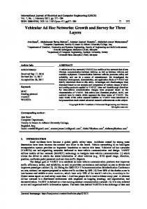
Figure 1: Data dissemination among vehicles on ToInfra stage.
sequence. Seq k denotes the pseudorandom sequence and is given by 𝑆𝑛 Seq 𝑘𝑎 = 𝑎 , 𝜛
𝜔
𝑦(𝑝)𝑖𝑗 = ∑ 𝑘𝑖𝑚 ∗ 𝑥(𝑝)𝑗𝑚
𝑎 = 1, 2, 3, . . . ,
𝑚=1 𝜔
𝜛 = max (𝜔, 𝜐) ,
(7)
𝑆𝑛𝑎 = (𝑆𝑛𝑎−2 + 𝑆𝑛𝑎−1 ) mod 𝜛, 𝑆𝑛−1 = VIDsource mod 𝜛,
𝑆𝑛0 = VID0 mod 𝜛,
𝑘𝑖𝑗 = Seq 𝑘𝑖∗𝜔+𝑗 .
(8)
𝐾 is the global coding matrix with 𝜆 × 𝜔 dimension and can be denoted as follows: 𝑘11 𝑘12 . . . 𝑘1𝜔 [𝑘21 𝑘22 . . . 𝑘2𝜔 ] ] [ 𝐾 = [ .. .. .. .. ] [ . . . . ] [𝑘𝜆1 𝑘𝜆2 . . . 𝑘𝜆𝜔 ] [ [ =[ [
Seq 𝑘2 Seq 𝑘𝜔+2 .. .
. . . Seq 𝑘𝜔 . . . Seq 𝑘2∗𝜔 ] ] ]. .. .. ] . . . . . Seq 𝑘𝜆∗𝜔 ]
[Seq 𝑘(𝜆−1)∗𝜔+1 Seq 𝑘(𝜆−1)∗𝜔+2
(9)
Implementing linear network coding on the blocks from the vehicle 𝑝 is formalized as computing the product of two matrixes. It is denoted as 𝑇
𝑌 (𝑝) = 𝐾 ⋅ 𝑋(𝑝) .
(11)
= ∑ Seq 𝑘𝑖∗𝜔+𝑚 ∗ 𝐵 (𝑝, (𝑗 − 1) ∗ 𝜔 + 𝑚, 𝑡) . 𝑚=1
where VIDsource is the unique identification of the source vehicle and VID0 is the unique identification of the vehicle executing network coding. The element 𝑘𝑖𝑗 in the matrix 𝐾 is gotten from Seq k and given by
Seq 𝑘1 Seq 𝑘𝜔+1 .. .
The dimension of matrix 𝑌(𝑝) is 𝜆 × 𝜐, and its element 𝑦(𝑝)𝑖𝑗 can be computed by
(10)
The blocks sourced from the different vehicles have the different opportunity if they send the whole matrix 𝑌(𝑝) successively. It is possible that the blocks sent later are not able to reach infrastructures. The movements of vehicles make the path unreachable. In order to make the equal opportunity for every vehicles transmitting information, the vehicles receiving active message only send an element of 𝑌(𝑝), then send an element of 𝑌(𝑝 + 1), and so on. An infrastructure can receive multiple network codes that source from the same 𝜔 consecutive blocks but are computed by local encoding matrix of different vehicles (see Figure 1). Receiver can decode the 𝜔 blocks of row 𝑖 completely when 𝑆𝑐(𝑝, 𝑖) ≥ 𝜔. 𝑆𝑐(𝑝, 𝑖) denotes the number of nonlinear codes received by the infrastructure and encoded by the 𝑖 row blocks of the vehicle 𝑝. The element of 𝑌(𝑝) in the same row is the nonlinear codes of the same 𝜔 blocks. The other vehicles also encode the 𝜔 blocks and send to the infrastructure. So the receiver maybe decodes the 𝜔 blocks completely when a vehicle only sends a few front elements of a row. The vehicle will send elements of coding matrix by columns. The infrastructure will send Break messages to the coding vehicles when 𝑆𝑐(𝑝, 𝑖) ≥ 𝜔. The vehicle breaks off network coding process when receiving Break messages. When the vehicle on ToInfra stage receives a message, its process is formally shown in Figure 2. Network coding algorithm on Figure 2 is described in Algorithm 1. 3.2. BeInfra Stage. Infrastructures are connected by wired media. They consist of wireless APs, network nodes, servers, and so on. It is able to guarantee the reliability and the real-time of data transmission among infrastructures.
International Journal of Distributed Sensor Networks
5 partition APs into subsets. First, 𝑟𝑖𝑗 denotes the relation strength between AP 𝑖 and j and is given by
Compare the message with messages in buffer
Receive a message
The message existed
Yes t=0
Buffer the message and count down time
Discard Judge the message type Yes Block
Active message l=0
Exist active messages
No l= l−1
1 𝑟𝑖𝑗 = { 𝛾 −1 [min (𝐷𝑖𝑗 ∗ (𝐻𝑖𝑗 ) )]
No
Code
𝑖 ≠ 𝑗.
(12)
𝛾 is a constant to adjust the weight of 𝐷𝑖𝑗 and 𝐻𝑖𝑗 , and 𝛾 ≥ 0. 𝐷𝑖𝑗 is the minimum delay (or the shortest path length) from AP 𝑖 to 𝑗, and 𝐻𝑖𝑗 is the hop count of the path. The value of 𝑟𝑖𝑗 is concerned with the shortest distance between two APs. The less the distance is, the more the 𝑟𝑖𝑗 value is. The relational matrix 𝑅 is defined as the following equation:
Yes
𝑅 = (𝑟𝑖𝑗 )𝑛×𝑛 ,
Network coding
where 𝑛 is the total number of APs in VANETs. In order to prove a fuzzy equivalence relation, we must demonstrate that 𝑅 is reflexive symmetrical and transitive [32]. 𝑅 is reflexive because all its diagonal elements are equal to 1. Suppose all links are dull-duplex in here, and their shortest path sourced either extremities is the same between −1 AP 𝑖 and 𝑗, and so 𝑟𝑖𝑗 = 𝑟𝑗𝑖 , 𝑅 = (𝑅 ) , 𝑅 is symmetrical. All of the other elements are less than diagonal elements, and so the inner product of 𝑅 is computed by
No
Epidemic
𝑖 = 𝑗;
Send to infrastructures
Figure 2: The process flowchart of vehicle on ToInfra stage.
The destinations of most blocks are not all of vehicles in VANET. We use multicast as the way of communication to aggregate data on BeInfra stage. Unicast and broadcast are regarded as two especial types of multicast in the method. Their group members are all or one node. When wireless AP receives the coding blocks from vehicles, it will send these blocks to another node according to their destinations. The node is the root of multicast tree. The root aggregates and recodes these blocks according to their destinations and then sends them to egress APs following the tree. Creating tree for every multicast group will make more forward states on middle node and cause more delay in data transmission. We aggregate all of multicast groups in a few share trees to resolve the former problem on BeInfra stage.
3.2.1. Constructing Multicast Shared Tree. The multicast group means the set of the APs leading to members rather than the set of the members themselves. The domain of infrastructures contains at least one Network Manager Server (NMS). It controls the computation of all shared trees. NMS maintains a link-state database describing the topology of infrastructures. There are one ingress router and multiple egress routers in a shared tree. The shared tree is rooted as a network node and leafing as egress APs. NMS selects routers as the root and leaves and computes the topology of shared tree. We partition all APs into subsets and cluster the members of all multicast group in the subsets in here then select the leaves and root of the shared tree. The method includes the detailed steps as the following. (1) Partitioning Aps. All APs are partitioned according to the topology of infrastructure networks. Clustering algorithms are required in here. We use fuzzy clustering algorithm to
2
(13)
𝑛
(𝑅 ) = 𝑅 ∘ 𝑅 = ( ∨ (𝑟𝑖𝑘 ∧ 𝑟𝑘𝑗 )) 𝑘=1
𝑛×𝑛
= (𝑟𝑖𝑗 )𝑛×𝑛 = 𝑅 . (14)
2
𝑅 is transitive because (𝑅 ) ⊆ 𝑅 . Therefore 𝑅 is a fuzzy equivalence relation. The partition of APs set can be got from 𝜆-cut sets of the 𝜆 fuzzy equivalence relation 𝑅 . The cut set is denoted as (𝑅 ) , and the value of its elements 𝑟𝑖𝑗𝜆 is obtained by the following equation: 𝑟𝑖𝑗𝜆 = {
0 𝑟𝑖𝑗 < 𝜆 1 𝑟𝑖𝑗 ≥ 𝜆.
(15)
The set of All LERs are partitioned into many subsets. The 𝜆 belongs to [0, 1]; the less the value of 𝜆 is, the more the number of subsets is. (2) Aggregating Members. NMS gives an identifier to every sub-set in the infrastructures domain and finds members of every multicast group according to the route-state tables of APs. Multicast member is replaced with the ID of sub-set including the member, and the multicast group G (member1 ,. . ., member𝑁) is transferred to 𝐺 (ID1 ,. . ., ID𝑀), which is defined as Class Group. The same IDs are merged into one element in 𝐺 . All multicast groups are indexed in 𝐺 and saved as their registration in NMS. NMS contrasts the 𝐺 in term of sub-set ID. The number of 𝐺 with the same ID is denoted as the compression parameter 𝐶. If 𝐶 is more than a specific threshold 𝛼 (𝛼 ⩾ 2), those groups are aggregated to use a Class Group. (3) Selecting Leaves. There is only one leaf for a shared tree in every sub-set. The leaf is an AP in or out the sub-set. NMS
6
International Journal of Distributed Sensor Networks
𝑆𝑛−1 = VIDsource mod 𝜛, 𝑆𝑛0 = VID0 mod 𝜛 For 𝑖 = 1 to 𝜆 For 𝑗 = 1 to 𝜔 𝑆𝑛 = (𝑆𝑛−1 + 𝑆𝑛0 ) mod 𝜛; 𝑆𝑛−1 = 𝑆𝑛0 ; 𝑆𝑛0 = 𝑆𝑛; 𝑘[𝑖, 𝑗] = 𝑆𝑛/𝜛; For 𝑗 = 1 to 𝜐 For every vehicle 𝑝 For 𝑖 = 1 to 𝜆 sum = 0; For 𝑚 = 1 to 𝜔 sum = sum + 𝑘[𝑖, 𝑚] ∗ 𝐵[𝑝, (𝑗 − 1) ∗ 𝜔 + 𝑚]; 𝑌[𝑝, 𝑖, 𝑗] = sum; Send 𝑌[𝑝, 𝑖, 𝑗] to next hop If receiving Break Message exit. Algorithm 1: Formal description of network coding on ToInfra stage.
finds the multicast groups, which are aggregated to one Class Group 𝐺 . Then NMS divides all members of those multicast groups into Vertex set according to sub-set ID. The members in same 𝐺 and sub-set are placed a Vertex set. The Vertex set is linked into a sub-graph of the infrastructures domain. The nodes of the sub-graph consist of all APs in the Vertex set and the routers as intermediate nodes. We select the median point of the sub-graph as the leaf of shared tunnel. The parameter 𝐷𝑖 , which denotes the sum of distances from a node 𝑖 in the sub-graph to all members of Vertex set, is computed by 𝑚
𝐶
𝑗=1
𝑘=1
𝐷𝑖 = ∑ (𝑑min (𝑖, 𝑗) ∗ ( ∑ 𝑏 (𝑗, 𝑘))) ,
(16)
where 𝑑min (𝑖, 𝑗) is the length of shortest path between node 𝑖 and member j and 𝑚 is the number of members in the Vertex set. The parameter 𝑡(𝑗, 𝑘) is the bandwidth that multicast group 𝑘 spares member 𝑗. The compression parameter 𝐶 is the number of multicast groups aggregated into the shared tree. 𝑏(𝑗, 𝑘) = 0 when multicast group 𝑘 does not include member 𝑗. NMS selects the node with the minimum parameter 𝐷 as the leaf of shared tree in the sub-set. (4) Selecting Multicast Root. The root of shared tunnel is selected by the method similar to the selecting leaves. It can be any node in the infrastructures domain. The parameter 𝑃𝑖 , which denotes the sum of distances from a node 𝑖 to all sources of multicast group aggregated into the tree, is defined by the following equation: 𝐶
𝑃𝑖 = ∑ (𝑑min (𝑖, 𝑗) ∗ 𝑇𝑗 ) ,
(17)
𝑗=1
where 𝑑min (𝑖, 𝑗) is the length of shortest path between node 𝑖 and source j and 𝑇𝑗 is the bandwidth occupied by multicast flow from source 𝑗. NMS selects the node with the minimum
parameter 𝑃 as the root of the shared tree. So the 𝑃 of root 𝑃𝑟 must satisfy the following condition: 𝐶
𝑃𝑟 = min ( ∑ (𝑑min (𝑖, 𝑗) ∗ 𝑇𝑗 )) . 1≤𝑖≤𝑁
(18)
𝑗=1
N is the number of nodes in the infrastructures domain. (5) Computing Multicast Shared Tree. NMS computes the shared tunnel tree for the Class Group which connects the selected root and leaves. It can use any existing multicast tree algorithm [22] (e.g. the Dijkstra’s algorithm, Steiner tree-based heuristic routing algorithm with the objective of minimizing the cost on multi-QoS constraint). How the multicast tree is computed in the algorithms is outside the scope of this paper. 3.2.2. Recoding on Root. APs send coding blocks to the roots of multicast shared tree according to their destinations. The root discards the same coding blocks and send Break messages to the coding vehicles when 𝑆𝑐(𝑝, 𝑖) ≥ 𝜔. Then the root will recode to the coding blocks with the same destinations and sources. The recoding blocks are transferred to the APs along the multicast shared tree. The APs in the tree cover the area where destinations vehicles arrive at or will arrive at. 𝜔 nonlinear codes of blocks in the same row are selected to recode with the global coding matrix, which is denoted as 𝐹. The matrix 𝐹 is unique and constant to the infrastructures and need not be transferred on VANETs. All vehicles have the duplicate copy of 𝐹 and decode the recoding blocks using 𝐹. All of elements in 𝐹 originate a pseudorandom sequence. Seq f denotes the pseudorandom sequence and is given by Seq 𝑓𝑎 =
(arc sin 𝑆𝑚𝑎 ) + 0.5, 𝜋
𝑆𝑚𝑎 = 1 − 2 ∗
2 𝑆𝑚𝑎−1 ,
𝑎 = 1, 2, 3, . . . ,
(19)
𝑆𝑚𝑎−1 ∈ (−1, 0.5) ∪ (0.5, 1) .
𝑆𝑚𝑎 is an intermediate variable to produce the sequence. Sm0 can be designated by the VANET administrator, and its
International Journal of Distributed Sensor Networks
7
𝑆𝑚 = 0.3; For 𝑖 = 1 to 𝜉 For 𝑗 = 1 to 𝜔 𝑆𝑚 = 1 − 2 ∗ 𝑆𝑚2 ; 𝑓[𝑖, 𝑗] = arcsin(𝑆𝑚)/𝜋 + 0.5; Select 𝜔 received rows from 𝑌 to 𝑌𝑠 ; For 𝑗 = 1 to 𝜐 For every vehicle 𝑝 For 𝑖 = 1 to 𝜉 sum = 0; For 𝑚 = 1 to 𝜔 sum = sum + 𝑓[𝑖, 𝑚] ∗ 𝑌[𝑝, 𝑚, 𝑗]𝑠 ; 𝑍[𝑝, 𝑖, 𝑗] = sum; Send 𝑍[𝑝, 𝑖, 𝑗] to leafs of multicast shared tree; If receiving ACK Messages of all leaves exit. Algorithm 2: Formal description of recoding on root.
default value is equal to 0.3. The element 𝑓𝑖𝑗 in the matrix 𝐹 is gotten from Seq f and given by 𝑓𝑖𝑗 = Seq 𝑓𝑖∗𝜔+𝑗 .
(20)
The dimension of matrix 𝐹 is 𝜉 × 𝜔, and its row sum 𝜉 can be computed by 𝜉=𝛽∗
𝜔 , Pr (𝑡)
Pr (𝑡) ≤ 1,
(21)
where Pr(𝑡) is the probability that blocks arrive at destination from the infrastructure in time t; it can be designated by the VANET administrator according to the APs density. 𝛽 is a guaranteed factor, where 𝛽 ≥ 2. Implementing recoding on the coding blocks is formalized as computing the product of matrixes. It is denoted as 𝑇 𝑠
𝑠
𝑍 (𝑝) = 𝐹 ⋅ 𝑌(𝑝) = 𝐹 ⋅ (𝐾 ⋅ 𝑋(𝑝) ) .
(22)
𝑌(𝑝)𝑠 is the 𝜔 nonlinear rows in matrix 𝑌(𝑝), and they are received and selected by root. The dimension of matrix 𝑍(𝑝) is 𝜉 × 𝜐, and its element 𝑧(𝑝)𝑖𝑗 can be computed by 𝜔
𝑠
𝜔
𝑠
𝑧(𝑝)𝑖𝑗 = ∑ 𝑓𝑖𝑚 ∗ 𝑦(𝑝)𝑚𝑗 = ∑ Seq 𝑓𝑖∗𝜔+𝑚 ∗ 𝑦(𝑝)𝑚𝑗 . (23) 𝑚=1
𝑚=1
The process of recoding on root is described in Algorithm 2. 3.3. ToVehic Stage. The leaves on multicast tree are the APs that may send blocks to destination vehicles within the designated time 𝑇max . Their communication ranges cover the location where vehicles are passing or will pass. The blocks are immediately sent out from APs after being recoded completely. Their live time 𝑡 = 𝑇max . The function and computation of live time are the same as the ToInfra stage. AP stops sending the recoded blocks of the same row when it receives the ACK message from vehicles and then returns the message to the root of multicast tree. AP also stops sending
when the 𝜉 recoded blocks are sent completely but does not return the ACK message. The vehicles buffer and send the blocks which 𝑡 ≠ 0. The destination vehicle will return the ACK message when it receives the 𝜔 nonlinear recoded blocks of the same row and then begins decoding. The method of reducing packet includes the detailed steps as the following. (1) Computing Coefficient Matrix. Coefficient matrix consists of the factors which the 𝜔 blocks multiply. It is denoted as G. 𝜔 (𝑍(𝑝)𝑠 ) is the received 𝜔 local encoding vectors and can be given by 𝑠 𝜔
𝜔
𝜔
(𝑍(𝑝) ) = 𝐺 ⋅ 𝑋 (𝑝) = (𝐹𝑠 ) ⋅ (𝐾𝑠 ) ⋅ 𝑋 (𝑝) . 𝜔
(24) 𝜔
(𝐹𝑠 ) is the 𝜔 rows of local encoding matrix in root. (𝐾𝑠 ) is the 𝜔 rows of local encoding matrix in vehicles. The number of rows is sent with the blocks. Their elements are generated from the designated pseudorandom sequence. Destination vehicle can generate the sequence in the same rule. The element 𝑔𝑖𝑗 in 𝐺 can be computed by 𝜔
𝑠 𝑠 ∗ 𝑓𝑚𝑗 𝑔𝑖𝑗 = ∑ 𝑘𝑖𝑚 𝑚=1
(25)
𝜔
= ∑ seq 𝑘(𝑖+𝑎)∗𝜔+𝑚 ∗ seq 𝑓(𝑚+𝑏)∗𝜔+𝑗 . 𝑚=1
𝑎 and 𝑏 are the values that the received number of rows 𝜔 𝜔 subtract the number of row in (𝐹𝑠 ) and (𝐾𝑠 ) , respectively. 𝜔
(2) Decoding the Recoding Blocks. The designated row of (𝐹𝑠 ) 𝜔 is constant to a VANET. The row of (𝐾𝑠 ) is variable because it changes with the vehicle IDs of source and coding. We do not decode the 𝑍(𝑝) to 𝑋(𝑝) directly but decode two 𝜔 blocks successively, because the constant matrix (𝐹𝑠 ) is easy to preprocess. The recoding blocks can be decoded by the below equation: 𝑠 𝜔
𝜔 −1
(𝑌(𝑝) ) = ((𝐹𝑠 ) )
𝑠 𝜔
⋅ (𝑍(𝑝) ) .
(26)
8
International Journal of Distributed Sensor Networks
Computing F 𝜔 and K𝜔 matrix
Computing coefficient matrix G
Preprocessing K𝜔 and recording
Looking up inverse matrix of F 𝜔
Decoding Y(p) to X(p)
our MCNC method in contrast with Epidemic, PRoPHET routing, and generic Wi-Fi.
Receive blocks
Receive the other block
Decoding Z(p) to Y(p)
Reducing the packets
Figure 3: The process flowchart of destination vehicle on ToVehic stage.
Matrix inverse is not usually used in the decoding process because it is complex and can exhaust the computing 𝜔 resource. In our case, (𝐹𝑠 ) is the subset of constant matrix 𝐹. All subsets of 𝐹 inverse can be precalculated in the mainframe computer. Their inverse matrixes are stored in vehicles as the table. The space occupied by the tables is 𝐶𝜉𝜔 ∗ 𝜔2 . This is storable to the vehicle. In this step, vehicles need not compute the inverse matrix, and they can find quickly the inverse matrix in the table according its rows sequence. So the decoding of the recoding blocks can be finished rapidly in (26). (3) Decoding the Coding Blocks. Destination vehicles can decode 𝑌(𝑝) to X(p) in any decoding algorithm on the 𝜔 step. We improve the step in preprocessing (𝐾𝑠 ) matrix. To obtain 𝑋(𝑝) matrix, a variant of the Gaussian elimination is used. A typical Gaussian elimination or LU decomposition restricts us to wait until we decoded the recoding block and 𝜔 had the 𝜔 × 𝜔 coefficient matrix [33]. However, 𝜔 decoding operation is started early in our case, and (𝐾𝑠 ) is preprocessed as the first block arrives. 𝑌(𝑝) is confirmed of the sequences of the rows and the IDs of coding vehicles on the root. The first block can carry this information to the destination vehicle. Destination com𝜔 𝜔 putes the (𝐾𝑠 ) matrix in advance. It preprocesses the (𝐾𝑠 ) in Gaussian elimination while receiving 𝑍(𝑝) and records the processing steps. These steps contain the processing order of rows and the multiplying coefficients of every row. After 𝑍(𝑝) is decoded to 𝑌(𝑝), the vehicle decodes 𝑌(𝑝) in the steps of 𝜔 preprocessing (𝐾𝑠 ) . Processing objects are only the elements of 𝑌(𝑝), and decoding 𝑌(𝑝) is speed-up. (4) Reducing the Packets. Destination composes the blocks of 𝑋(𝑝) into the packets. The packets are reduced completely. The steps are formally shown in Figure 3.
4. Evaluation In this section, we generate the movement of vehicles on the ONE simulator [34] and evaluate the performance of
4.1. Simulation Setup. The ONE simulator uses the Helsinki city map and generates node movement and routing [35]. We extract the area with the range of 4000 m × 3000 m from the map and configure two types of network nodes. Vehicle node moves on the map at the speed of 10 to 50 km/h and waits time of 10 to 120 seconds to stop communication after arriving to the destination. The vehicles choose random destinations on the map and move there following the shortest path. AP node is static and communicates with other APs in wired links. The radio range is configured as 200 m, and the MAC protocol is IEEE 802.11. Epidemic replicates messages to all encountered nodes that do not have them yet. PRoPHET only sends messages to the nodes that have the highest chances to deliver the messages to the destination. They are two typical routing protocols for ad hoc networks and have been implemented by the users of the ONE simulator as add-ons. In generic WiFi, vehicles data must be delivered by APs in the radio range, and the routing capability of vehicles is disabled. Two scenarios are generated in the evaluation. A sparse network with 30 vehicles simulates the rural area. A dense network with 150 vehicles simulates the urban area. The other parameters of MCNC method are listed as follows. The TTL of the active message 𝐿 max = 2 or 5. The live time of blocks among vehicles 𝑇max = 300 seconds. The dimension of encoding vector 𝜔 = 10. The number of APs is variable. 4.2. Performance Analysis. The measured parameters on the simulator are the block loss rate, transmission delay, and overhead messages. Block loss rate [13] is the ratio of lost blocks to the sending blocks from sources. Transmission delay is the time of a block delivered from the source to all destinations. Overhead ratio [13] is the effective blocks as the percentage of all forwarding blocks among vehicles. They synthetically reflect the performance of MCNC. The simulation lasts for 30 minutes. The 10 sources in 2 scenarios are selected to generate flows for the evaluation. The average values of the 3 parameters are presented as the basis for analyzing their performance. Figure 4 shows the average blocks loss rate in the sparse scenario. It is easy to see that as the number of APs increases, blocks loss rate decreases in the five data plots. When the number of APs is 80, the radios of APs cover the whole area and blocks loss rate is 0 for all the method. Epidemic has the less loss rate than the others, since it sends copies to all encountered vehicles and transmits successively in the greatest probability. Generic Wi-Fi is the most loss rate and cannot be used while APs only cover part of area. PRoPHET also cannot delivery many blocks to the destinations in the sparse scenario. MCNC is close to Epidemic in blocks loss rate. When the cover area of APs is 1/5 (the number of APs is 16 in Figure 4), the blocks loss rate of MCNC is less than 0.2, and it can reach the target of transmission reliability. 𝐿 max has some influence on the parameter. The values of the parameter
International Journal of Distributed Sensor Networks
9
1
1100
0.9
1000 Transmission delay (s)
0.8 Blocks loss rate
0.7 0.6 0.5 0.4 0.3 0.2
700 600 500
300 0
4
8
12
16
20
25
35
50
80
Number of APs MCNC (L max = 2) MCNC (L max = 5) Epidemic
PRoPHET Generic Wi-Fi
0.25 0.2 0.15 0.1 0.05
4
8
12
16 20 25 Number of APs
MCNC (L max = 2) MCNC (L max = 5) Epidemic
35
4
8
12
16 20 25 Number of APs
50
35
50
80
PRoPHET Generic Wi-Fi
Figure 6: Transmission delay in the sparse scenario.
0.3
0 0
0
MCNC (L max = 2) MCNC (L max = 5) Epidemic
Figure 4: Blocks loss rate in the sparse scenario.
Blocks loss rate
800
400
0.1 0
900
80
PRoPHET Generic Wi-Fi
Figure 5: Blocks loss rate in the dense scenario.
will increase weakly while 𝐿 max is changed from 2 to 5. With the increase of hops after network coding and aggregating, the block loss rate only increases 0.04 when the number of APs is 16. Figure 5 is similar to Figure 4. Generic Wi-Fi is unchangeable in different scenarios. Figure 5 only shows a part plot of generic Wi-Fi. The other methods all decrease their blocks loss rate in dense scenario. MCNC in the scenario is closer to Epidemic than the sparse scenario. When the cover area of APs is 1/5, the blocks loss rate of MCNC decreases to less than 0.08. The changes of 𝐿 max do not have strong influence on the transmission reliability of MCNC.
Figure 6 shows the average delay of blocks that are transmitted successively to destinations in the sparse scenario. Generic Wi-Fi only deliver few blocks to destinations while the number of APs is less than 20. Its delay changes randomly and does not associate with the number of APs and vehicles. The other methods all decrease the transmission delay with the increase of APs. PRoPHET only takes one of encountering vehicles as the next hop. Although the vehicle has the highest chance to destinations, it maybe moves more time to send block. So the delay of PRoPHET is more than the other methods. MCNC is also near to Epidemic in delay. Their delays are same in no AP setting. MCNC use APs to delivery blocks, but increase in little delay. When the cover area of APs is 1/5, the delay of MCNC is more 8% than Epidemic, and it can reach the target of transmission real-time. The changes of 𝐿 max have some influence on the delay of MCNC. The delay increases less than 10% when 𝐿 max is changed from 2 to 5. The delays of four methods in dense scenario are shown in Figure 7, which is similar to Figure 6. They all decrease their delays in the dense scenario. Their delays are closer than the sparse scenario. When the number of APs is 16, the delay of MCNC is more than 6% Epidemic, PRoPHET is more than 22% Epidemic, and the delay increases less than 3% with the change of 𝐿 max from 2 to 5. Figure 8 shows the average overhead radios, which are the same in all test scenarios. Generic Wi-Fi does not generate overhead messages on any conditions, and its values are always least in four methods. Epidemic generates most overhead messages, which rise with the increase of APs, since AP also sends Epidemic message to the other vehicles. For this reason, PRoPHET also generates more overhead messages while setting more APs. MCNC has the same overhead ratio with Epidemic in no AP setting. With the increase of the number of APs, the overhead messages begin to decrease rapidly in MCNC. The rate of decrease is diminished after
10
International Journal of Distributed Sensor Networks PRoPHET. So the 2/3 overhead messages are cut down, and the scalability of VANETs is improved. Given all that, MCNC is able to achieve lower overhead ratios than both Epidemic and PRoPHET. Its blocks loss ratio and delay are tiny higher than Epidemic but lower than the other methods. It aggregates greater part of overhead messages using multicast and network coding. Installing APs in part of area can improve the performance of MCNC in any scenario. MCNC is appropriate for the areas that APs have been deployed but cannot cover entirely.
600
Transmission delay (s)
550 500 450 400 350
5. Conclusion
300 0
4
8
12
16
20
25
35
50
80
Number of APs MCNC (L max = 2) MCNC (L max = 5) Epidemic
PRoPHET Generic Wi-Fi
Figure 7: Transmission delay in the dense scenario. 4500 4000
Overhead ratio (%)
3500 3000 2500 2000 1500 1000
VANET can use APs as the infrastructures to improve its performance. Our works aggregate messages in multicast trees on infrastructures networks mainly consisted of APs and implement network coding on the vehicles that the hop to APs is less than 𝐿 max . We divide data transmission into 3 stages: ToInfra, BeInfra, and ToVehic. Network coding, multicast aggregating, and decoding are implemented in the 3 stages, respectively. Data dissemination uses the generic routing algorithm for VANETs before network coding. The experiments show that our MCNC is able to cut down 2/3 overhead messages of Epidemic when the cover area of the APs is 1/5. The costs of aggregations are a tiny improvement of delay. The blocks loss ratio and transmission delay of MCNC are also lower than the other methods. The performance of MCNC is similar in sparse scenario and dense scenario. In many places, Wi-Fi based APs can be deployed, but their radios cannot cover the whole area of vehicles movement, and MCNC will exert the promoting affluence on the development of VANETs.
Acknowledgments
500 0
0
4
8
12
16
20
25
35
50
80
Number of APs MCNC (L max = 2) MCNC (L max = 5) Epidemic
PRoPHET Generic Wi-Fi
The work is supported in part by the National Science Foundation of China under Grant nos. 61202378, 61070169, and 61070170, University Science Research Project of Jiangsu Province under Grant no. 11KJB520017, the Natural Science Foundation of Jiangsu under Grant no. BK2011376, and Suzhou Application Foundation Research Project under Grant nos. SYG201238 and SYG201118.
Figure 8: Overhead ratio of the four methods.
References the cover area of the APs is more than 1/4 (the number of APs is 16). MCNC reduces the overhead message after network coding and aggregates the flows in multicast share trees on infrastructures. So its aggregating ability is obvious. The changes of 𝐿 max have huge influence on the overhead ratio of MCNC. The greater 𝐿 max is, the less the overhead ratio is and the more the aggregating ability is. With 𝐿 max changing from 2 to 5, the overhead ratio cuts down more than 1/2 after the cover area of the APs is more than 1/4. If 𝐿 max and the number of APs satisfy the requirements, blocks can be coded and sent to APs after leaving the sources. The overhead ratio of MCNC (𝐿 max = 5) is 1200% when the cover area of the APs is 1/5. This value is the 1/3 of Epidemic and even less than
[1] F. Farnoud and S. Valaee, “Reliable broadcast of safety messages in vehicular Ad hoc networks,” in Proceedings of the IEEE INFOCOM 2009, pp. 226–234, Rio de Janeiro, Brazil, April 2009. [2] J. Zhu, Y. Feng, and B. Liu, “PASS: parking-lot-assisted carpool over vehicular Ad hoc networks,” International Journal of Distributed Sensor Networks, vol. 2013, Article ID 491756, 9 pages, 2013. [3] K. C. Lee, S. H. Lee, R. Cheung, U. Lee, and M. Gerla, “First experience with CarTorrent in a real vehicular Ad hoc network testbed,” in Proceedings of the Mobile Networking for Vehicular Environments (MOVE ’07), pp. 109–114, Anchorage, Alaska, USA, May 2007.
International Journal of Distributed Sensor Networks [4] U. Lee, J. Lee, J. Park, and M. Gerla, “FleaNet: a virtual market place on vehicular networks,” IEEE Transactions on Vehicular Technology, vol. 59, no. 1, pp. 344–355, 2010. [5] G. Karagiannis, O. Altintas, E. Ekici et al., “Vehicular networking: a survey and tutorial on requirements, architectures, challenges, standards and solutions,” IEEE Communications Surveys and Tutorials, vol. 13, no. 4, pp. 584–616, 2011. [6] M. J. Khabbaz, C. M. Assi, and W. F. Fawaz, “Disruption-tolerant networking: a comprehensive survey on recent developments and persisting challenges,” IEEE Communications Surveys and Tutorials, vol. 14, no. 2, pp. 607–640, 2012. [7] S. Olariu and M. C. Weigle, Vehicular Networks: From Theory to Practice, CRC Press/Taylor & Francis, 2009. [8] Y. Wu, Y. Zhu, and B. Li, “Infrastructure-assisted routing in vehicular networks,” in Proceedings of the IEEE INFOCOM 2012, pp. 1485–1493, Orlando, Fla, USA, March 2012. [9] J. Jaehoon, G. Shuo, G. Yu, H. Tian, and D. Du, “TBD: trajectory-based data forwarding for light-traffic vehicular networks,” in Proceedings of the 29th IEEE International Conference on Distributed Computing Systems Workshops (ICDCS ’09), pp. 231–238, Montreal, Canada, June 2009. [10] D. Jiang and L. Delgrossi, “IEEE 802.11p: towards an international standard for wireless access in vehicular environments,” in Proceedings of the IEEE Vehicular Technology ConferenceSpring (VTC ’08), pp. 2036–2040, Singapore, May 2008. [11] J. Eriksson, L. Girod, B. Hull, R. Newton, S. Madden, and H. Balakrishnan, “The pothole patrol: using a mobile sensor network for road surface monitoring,” in Proceedings of the 6th International Conference on Mobile Systems, Applications, and Services, pp. 29–39, June 2008. [12] Y. M. Zhu, X. M. Liu, M. L. Li, and Q. Zhang, “POVA: traffic light sensing with probe vehicles,” in Proceedings of the INFOCOM 2012, pp. 2661–2665, 2012. [13] A. Palma, P. R. Pereira, and A. Casaca, “Multicast routing protocol for vehicular delay-tolerant networks,” in Proceedings of the IEEE 8th International Conference on Wireless and Mobile Computing, Networking and Communications (WiMob ’12), pp. 753–760, Barcelona, Spain, October 2012. [14] J. Eriksson, H. Balakrishnan, and S. Madden, “Cabernet: vehicular content delivery using WiFi,” in Proceedings of the 14th Annual International Conference on Mobile Computing and Networking (MobiCom ’08), pp. 199–210, September 2008. [15] V. Bychkovsky, B. Hull, A. Miu, H. Balakrishnan, and S. Madden, “A measurement study of vehicular internet access using in situ Wi-Fi networks,” in Proceedings of the 12th Annual International Conference on Mobile Computing and Networking (MOBICOM ’06), pp. 50–61, September 2006. [16] N. Banerjee, M. D. Corner, and B. N. Levine, “An energyefficient architecture for DTN throwboxes,” in Proceedings of the 26th IEEE International Conference on Computer Communications (IINFOCOM ’07), pp. 776–784, Anchorage, Alaska, USA, May 2007. [17] P. Rodriguez, R. Chakravorty, J. Chesterfield, I. Pratt, and S. Banerjee, “MAR: a commuter router infrastructure for the mobile internet,” pp. 217–230, 2004. [18] J. Zhao, Y. Zhang, and G. Cao, “Data pouring and buffering on the road: a new data dissemination paradigm for vehicular Ad hoc networks,” IEEE Transactions on Vehicular Technology, vol. 56, no. 6, part 1, pp. 3266–3277, 2007. [19] B. B. Chen and M. C. Chan, “MobTorrent: a framework for mobile internet access from vehicles,” in Proceedings of the IEEE
11
[20]
[21]
[22]
[23]
[24]
[25]
[26]
[27]
[28]
[29]
[30]
[31]
[32] [33]
[34] [35]
INFOCOM 2009, pp. 1404–1412, Rio de Janeiro, Brazil, April 2009. I. Leontiadis, P. Costa, and C. Mascolo, “Extending access point connectivity through opportunistic routing in vehicular networks,” in Proceedings of the IEEE INFOCOM 2010, pp. 1–5, San Diego, Calif, USA, March 2010. J. Jeong, S. Guo, Y. Gu, T. He, and D. Du, “Trajectory-based statistical forwarding for multihop infrastructure-to-vehicle data delivery,” IEEE Transactions on Mobile Computing, vol. 11, no. 10, pp. 1523–1537, 2012. J. Jeong, S. Guo, Y. Gu, T. He, and D. H. C. Du, “Trajectory-based data forwarding for light-traffic vehicular Ad hoc networks,” IEEE Transactions on Parallel and Distributed Systems, vol. 22, no. 5, pp. 743–757, 2011. N. Liu, M. Liu, G. Chen, and J. Cao, “The sharing at roadside: vehicular content distribution using parked vehicles,” in Proceedings of the IEEE INFOCOM 2012, pp. 2641–2645, Orlando, Fla, USA, March 2012. N. Liu, M. Liu, W. Lou, G. Chen, and J. Cao, “PVA in VANETs: stopped cars are not silent,” in Proceedings of the IEEE INFOCOM 2011, pp. 431–435, Shanghai, China, April 2011. W. Vogels, R. Renesse, and K. Birman, “The power of epidemics: robust communication for large-scale distributed systems,” ACM SIGCOMM Computer Communication Review, vol. 33, no. 1, pp. 131–135, 2003. A. Lindgren, A. Doria, and O. Schelen, “Probabilistic routing in intermittently connected networks,” ACM SIGMOBILE Mobile Computing and Communications Review, vol. 7, no. 3, pp. 19–20, 2003. U. Lee, J. Park, J. Yeh, G. Pau, and M. Gerla, “CodeTorrent: content distribution using network coding in VANET,” in Proceedings of the 1st International Workshop on Decentralized Resource Sharing in Mobile Computing and Networking (MobiShare ’06), pp. 1–5, ACM, September 2006. M. Li, Z. Yang, and W. Lou, “CodeOn: cooperative popular content distribution for vehicular networks using symbol level network coding,” IEEE Journal on Selected Areas in Communications, vol. 29, no. 1, pp. 223–235, 2011. M. Sathiamoorthy, A. G. Dimakis, B. Krishnamachari, and F. Bai, “Distributed storage codes reduce latency in vehicular networks,” in Proceedings of the IEEE INFOCOM 2012, pp. 2646–2650, Orlando, Fla, USA, March 2012. V. Palma, E. Mammi, A. M. Vegni, and A. Neri, “A fountain codes-based data dissemination technique in vehicular Ad-hoc networks,” in Proceedings of the 11th International Conference on ITS Telecommunications (ITST ’11), pp. 750–755, August 2011. S. Primak, V. Lyandres, O. Kaufman, and M. Kliger, “On the generation of correlated time series with a given probability density function,” Signal Processing, vol. 72, no. 2, pp. 61–68, 1999. Z. Pawlak, “Rough sets,” International Journal of Computer and Information Science, vol. 11, no. 5, pp. 341–356, 1982. T. Ho, M. M´edard, R. Koetter et al., “A random linear network coding approach to multicast,” IEEE Transactions on Information Theory, vol. 52, no. 10, pp. 4413–4430, 2006. The ONE, http://www.netlab.tkk.fi/tutkimus/dtn/theone/. A. Ker¨anen, T. K¨arkk¨ainen, and J. Ott, “Simulating mobility and DTNs with the ONE,” Journal of Communications, vol. 5, no. 2, pp. 92–105, 2010.
International Journal of
Rotating Machinery
Engineering Journal of
Hindawi Publishing Corporation http://www.hindawi.com
Volume 2014
The Scientific World Journal Hindawi Publishing Corporation http://www.hindawi.com
Volume 2014
International Journal of
Distributed Sensor Networks
Journal of
Sensors Hindawi Publishing Corporation http://www.hindawi.com
Volume 2014
Hindawi Publishing Corporation http://www.hindawi.com
Volume 2014
Hindawi Publishing Corporation http://www.hindawi.com
Volume 2014
Journal of
Control Science and Engineering
Advances in
Civil Engineering Hindawi Publishing Corporation http://www.hindawi.com
Hindawi Publishing Corporation http://www.hindawi.com
Volume 2014
Volume 2014
Submit your manuscripts at http://www.hindawi.com Journal of
Journal of
Electrical and Computer Engineering
Robotics Hindawi Publishing Corporation http://www.hindawi.com
Hindawi Publishing Corporation http://www.hindawi.com
Volume 2014
Volume 2014
VLSI Design Advances in OptoElectronics
International Journal of
Navigation and Observation Hindawi Publishing Corporation http://www.hindawi.com
Volume 2014
Hindawi Publishing Corporation http://www.hindawi.com
Hindawi Publishing Corporation http://www.hindawi.com
Chemical Engineering Hindawi Publishing Corporation http://www.hindawi.com
Volume 2014
Volume 2014
Active and Passive Electronic Components
Antennas and Propagation Hindawi Publishing Corporation http://www.hindawi.com
Aerospace Engineering
Hindawi Publishing Corporation http://www.hindawi.com
Volume 2014
Hindawi Publishing Corporation http://www.hindawi.com
Volume 2014
Volume 2014
International Journal of
International Journal of
International Journal of
Modelling & Simulation in Engineering
Volume 2014
Hindawi Publishing Corporation http://www.hindawi.com
Volume 2014
Shock and Vibration Hindawi Publishing Corporation http://www.hindawi.com
Volume 2014
Advances in
Acoustics and Vibration Hindawi Publishing Corporation http://www.hindawi.com
Volume 2014