International Conference on Electrical, Control and Computer Engineering Pahang, Malaysia, June 21-22, 2011
Measurement of Vertical Electric Fields from Lightning Flashes using Parallel Plate Antenna W.I.Ibrahim, M.R. Ghazali, S.A. Ghani
Zulkurnain Abdul Malek
Faculty of Electrical & Electronics Engineering Universiti Malaysia Pahang 26600 Pekan, Pahang
[email protected],
[email protected],
[email protected]
Institute of High Voltage & High Current Universiti Teknologi Malaysia Skudai, Malaysia
[email protected]
Abstract— Lightning is the transfer of significant charge between two charged object, it can occur between cloud to cloud, cloud to air and cloud to ground. Lightning strikes can kill people, knock out radio communication, electrical power devices, and destroy houses, trees as well as animals. The lightning strike hazards may be properly managed by using a lightning detector system. The detection concepts can be based on Electromagnetic Field or Electric field . In this paper, the characteristics of the flat plate antenna in measuring the electric field has been reviewed and analysed. The experiment using parallel plate antenna has been setup to detect the E field during the thunderstorm days. The E- field data has been collected and used for data manipulation or others application.
Figure 1. Illustration of lightning operating frequency[1]
Keywords—Electric field, lightning, flat metallic plate antenna, parallel plate antenna.
I.
Lightning sensors were used to detect and locate electrical activity in thunderstorms using a number of different methodologies. These include direction finding (DF) [2], timeof-arrival (TOA) techniques [3], a combination of these two [4], and interferometry methods [5]. All techniques need a number of sensors within a network to get reliable data on the location of a lightning flash. The DF method basically uses two orthogonal magnetic loop antennas, where the azimuth angle to the flash is obtained by simple trigonometry. The TOA method uses the small differences in the arrival times of the radio wave at different stations to determine the optimum distance to the flash from a network of synchronized stations. The stations can be located between several kilometers until hundred kilometers in range. Today with GPS timing, the TOA method supplies more accurate locations compared with the DF methods. However, today combinations of both methods are often used to enhance the accuracy of lightning detection networks. In order the measure the lightning electric field intensity, several types of sensors have been developed. These sensors can be a vertical whip antenna, field mill and flat plate antenna. The vertical whip antenna [6] is a metal object connected to the ground through electric circuitry. On the thunderstorm day, when the E-Field varies in time, the charge
INTRODUCTION
Lightning is an electrical discharge either within the clouds (intra-cloud), between the clouds (inter-cloud) and cloud to the ground (CG). The fast acceleration of charge during the lightning flash generates electrostatic and electromagnetic radiation in all frequency bands. Radio waves from lightning can propagate around the globe over thousands of kilometers, and further within the Earth-ionosphere waveguide. The attenuation of these radio waves depends on the frequency of the radiation. Fig.1 [1] shows the differences in the rates and amplitudes of the electric field and electromagnetic radiation at the different frequencies. The different techniques are better suited for detecting various processes in cloud and CG flashes.
978-1-61284-230-1/11/$26.00 ©2011 IEEE
466
In the case of lightning E- field [9] measurements by using plat antenna (Fig.3) , consider the plate is over ground level in a time varying and also the wavelength of the E- Field is much larger than the size of the metallic plate. Then, the concept of the E-Field is defined as the force per unit charge for each point in a region of charges,
induced on the antenna also varies in time. Hence, it will generate the current in the electric circuitry. The field mills [7] is a device to measure the electric field strength on earth due to the static E-field and the charge of clouds passing overhead. It consists of one or two electrodes which either rotate in an electrostatic field or become periodically exposed to a field by rotating vanes. The simplify version of fill mills [8] is shown in Fig.2. In this paper the plat plate antenna and the parallel plate antenna were discussed for the lightning electric field measurements. The analysis of the measuring system was derived and discussed.
E=
F Q = Q 4πε D ε r r 2
Where Q represent the charge, r the distance, ε D and absolute and relative permitivities respectively.
(1)
ε r the
The term Eε D ε r is a density measure and is called electric flux density. This is a measure of the electric field flowing out of the sphere. Mathematically expresses as,
D = Eε D ε r
(2)
By referred to the Gauss`s law; the electric flux flowing out of a closed surface is equal to the charge enclosed, and it is mathematically expressed as
∫ D.ds = Q
(3)
s
Figure 2. Shutter type electric field mill for measurement of the polarity and magnitude of an electrostatic field.
II.
When the charge is uniformly distributed within the region, it is better to use a charge density per unit volume ρ instead of charge enclosed by a surface. Hence, integrate over the volume v , Gauss`s Law become
THEORY
A. Voltage in a Metallic Plate
∫ D.ds = ∫ pdv s
(4)
v
In this case, consider a flat plate over ground level in a time varying electric field and the wavelength of the E-field is much larger than the size of the plate. In the moment, a charge Q is induced when the E field appears on that plate. Therefore, equation (4) becomes, Electric Flux Density X Area of plate= Charge on plate And it is mathematically expressed as,
D.S = Q
(5)
From equation (2), the normal electric field becomes En = Figure 3. Flat metallic plate above ground level
467
Q
ε oε r S
(6)
Then the voltage between the flat –metallic plate and ground is; d
∫
V g = − E n dx = − 0
Q ε o .ε r .S
d
∫ (− 1)dx = ε 0
Q.d o .ε r .S
Vg =
(7)
ε Dε r S C1
En
(11)
Where V g is the voltage measured through the capacitance C1 , S is surface of the metallic plate and E n is the normal electric field.
If substitute equation (6) into (7), therefore; V g = E n .d
If the resistor R has been used between the metallic plate and ground to measure the voltage, the current through will be;
(8)
Equation (8) indicates that the voltage between the metallic plate and ground is directly proportional to the electric field normal to the plate and it height respect to the ground. Suppose the electric element was attached to the antenna as shown in Fig.4.
i=
dQ dt
(12)
And the voltage is;
V g = Ri
(13)
Therefore, substituting (12) and (13) in the derivative of (6);
V g = ε D ε r RS
dE n dt
(14)
Equation (14) clearly shown that the voltage depends on the derivative of the E-field. Now, supposed that the element of resistance and capacitance was attached to the antenna (in Fig5). The measured voltage Vm became less than V g due to RC effect.
Figure 4. Electric Element attached the antenna
The E-field can be found by measuring the varying-time current flowing through the electric element connected between the metallic plate and ground. But, the current totally depend on what type of electric element has been used. The measurement current could be the normal E-Field or the derivative of the E-field. If the capacitance has been used as the electric element between the metallic plate and ground to measure the voltage, then by integrating the current;
Q = V g .C1
Q = ∫ idt
(9) (10)
Figure 5. RC circuit attach to antenna
Therefore, substituting (9) in (6)
468
the interfacing between the software and hardware equipments. The parallel plate antenna was connected to the digital signal oscilloscope (DSO) by coaxial cable. The system interface, hardware and software development has been explained in [10] and [11].
Assuming the impedance of the R is very large compared to C. By neglecting R, the amplitude voltage Vm is equal to;
Vm = E n d
Cg Cg + C
= Vg
Cg Cg + C
(15)
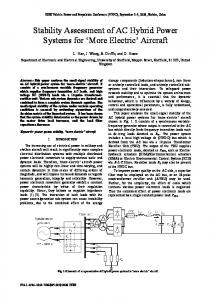
The equation (15) showed that the measured voltage Vm is the voltage V g times the capacitive divider composed by the capacitance C and the capacitance of the antenna with respect to the ground C g . B. Measuring System In the experiments, the parallel plate antenna was used to measure the E-field of lightning phenomena. The antenna composed by two (2) metallic and parallel plates. It was separated by a certain distance and the bottom plate is connected to the ground. Under this condition, the height d in equation (15) has to be modified to effective height. Fig.6 has shown the equivalent of the parallel plate antenna to measure the voltage. C c Is the capacitance of the coaxial cable to link the antenna and equipment. Hence, the measured voltage is;
Vm = E n d eff
Cg C g + Cc + C
(16) Figure 7. Parallel plate antenna to measure the E-field.
Figure 6. Equivalent circuit of the parallel plate antenna
III.
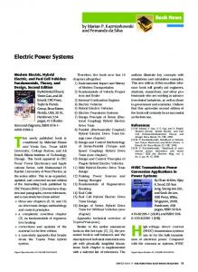
EXPERIMENT Figure 8. Parallel plate antenna at the top of IVAT building.
The experiment was conducted and the lightning data has successfully captured during the thunderstorm days. Fig.7 showed the arrangement of the experiment setup consists of
Fig.8 showed the parallel plate antenna that has been used to measure the E-field. The antenna was placed at the top of
469
Institute of High Voltage & High Current (IVAT), UTM. The application of the antenna has been explained in [10] - [13] .The antenna has been used to determine the distance [10], [11] of the lightning from the point where the strike occurred. In [12], the signatures of the electric pulses generated from cloud flash have been analyzed for different parameter. IV.
RESULT AND DISCUSSION
The lightning data was captured during January 2010 to March 2010 using the parallel plate antenna. Fig. 9 showed one of the E-field signals has successfully captured by the system. The measured voltage Vm , had a peak magnitude of 0.12V. Figure 11. Measurement Snapshot DSO TDS 5104B
Electric Field Signal
Voltage (V)
Fig.10 showed the highest E- Field Signal captured by the digital signal oscilloscope (DSO) and Fig.11 showed the data measurement from that signal. The max Vm is 1.44 and 12.535 MHz frequency has been recorded. It proved that parallel plate antenna was used to capture VHF signal during the thunderstorm days. Table1 below showed the total of lightning strokes that successfully captured by the parallel plate antenna by online system monitoring. TABLE1. THE QUANTITY OF STROKES Time (s) Figure 9. Electric Field Transducer Voltage Signal (15 March 2010, 15:19)
Obviously, the magnitude of the signal is dependent on the lightning strike intensity, and the lightning strike distance from the measuring antenna. On average, most of the captured electric field signals had a peak magnitude of 0.14V or greater.
Voltage (V)
Electric Field Signal
Date
Time
E = Vm / m
1615-1650
Quantity strokes 7
2 January 2010 3 January 2010
1650-1725
6
0.08
5 January 2010
1720-1800
8
0.12
6 January 2010
1615-1635
9
1.44
26 February 2010
1740-1750
4
0.5
28 February 2010
1720-1830
15
0.22
2 March
1700-1720
4
0.2
3 March
1810-1830
5
0.21
15 March
1455-1530
4
0.15
16 March
1350-1420
2
0.2
21 March
1545-1650
10
0.12
24 March
1700-1745
8
0.15
25 March
1600-1650
9
0.14
26 March
1500-1550
15
0.36
29 March
1600-1850
23
0.51
V.
Time (uS)
0.16
CONCLUSION
Figure 10. Ref1, Electric Field Transducer Voltage Signal (6 Jan 2010, 17:05)
The parallel plate antenna has been used to detect the electric field signal during the thunderstorm days. The most important aspects in the lightning electric field intensity measurement are the operation of the measuring system. The
470
operative characteristic of the parallel plate antenna has been derived and reviewed. It shows that, the characteristics of the antenna are most important as the first step in designing the measuring system for the E-field.
[5]
[6]
ACKNOWLEDGMENT
[7]
The Authors wish to thank for the support of this research to the Institute of High Voltage & High Current (IVAT), Universiti Teknologi Malaysia that made this collaborative work possible.
[8] [9]
REFERENCES [10] [1]
[2]
[3]
[4]
Kenneth L. Cummins ,History, Martin J. Murphy Techniques, and Data Uses, With an In-Depth Look at the U.S. NLDN. IEEE Transaction on Electromagnetic Compatibility, Vol. 51, August 2009. Krider, E.P.; Noggle, R.C.; Uman, M.A. A gated wideband magnetic direction-finder for lightning return strokes. J. Appl. Meteor. 1976, 15, 301-306 Lee, A.C.L. Ground truth confirmation and theoretical limits of an experimental VLF arrival time difference lightning flash locating system. Quart. J. Roy. Meteor. Soc. 1989, 115, 1147-1166 Cummings, K.L.; Murph, M.J.; Bardo, E.A.; Hiscox, W.L.; Pyle, R.B.; Pifer, A.E. A combined TOA/MDF technology upgrade of the US
[11]
[12]
[13]
471
National Lightning Detection Network. J. Geophys. Res. 1998, 103 D8, 9035-9044. Hayenga, C.O.; Warwick, J.W. Two-dimensional interferometric positions of VHF lightning sources. J. Geophys. Res. 1981, 86, 74517462. Vernon Cooray, The Lightning Flash, IEE Power & Energy Series 34, 2003. John N. Chubb, Two New Designs of “Field Mill” Type Fieldmeters not Requiring Earthing of Rotating Chopper, IEEE Transaction on Industry Application Vol. 26, Nov 1990. David A. Hill, Motohisa kanda ,Electric Field Strength ,CRC Press LLC ,2000. Artura Galvan, Mahendra Fernando, Operative characteristic of a parallel plate antenna to measure vertical electric field from lightning flashes,Uppsala 2000 Zulkurnain Abdul Malek, W.I.Ibrahim, Lightning Distance Determination based on Single station observation using VHF Electric Field, Asia Pacific Symposium on Applied Electromagnetics and Mechanics, July 2010. W.I. Ibrahim, Zulkurnain Abdul Malek, Time to thunder Method of lightning Distance Determination, IEEE International Conference on Power & Energy, Dec. 2010 S.R. Sharma, M. Fernando,C. Gomes, Signatures of electric field pulses generated by cloud flashes, Journal of Atmospheric and Solar-Terrestrial Physics 67 (2005) 413–422 RedyMardiana,Eprido Meiladi, A technique for lightning reconstructions using short-baseline broadband time of arrival, 14th Asian Conference on electrical discharge, Nov. 2008.