C. Adolphsen, K. Bane, G. Loew, R. Ruth, K. Thompson, J. Wang. Stanford Linear Accelerator Center, Stanford University, Stanford California 94309.
SLAC-PUB-594 1 October 1 9 9 2 (A>
-
-s-C
M e a s u r e m e n t o f W a k e fields G e n e rate d in A ccelerator T e s t S tru c tures U s i n g th e S L C * C . A d o l p h s e n , K . B a n e , G . L o e w , R . R u th , K . T h o m p s o n , J. W a n g S ta n fo r d L i n e a r Accelerator C e n te r , S ta n fo r d University, S ta n fo r d California 9 4 3 0 9
ABSTRACT R e s e a r c h is u n d e r w a y at S L A C to d e v e l o p accelerator structures for the next generation linear collider. A n important feature of the design is a detuning of the dipole m o d d e s-of the cells to suppress the l o n g - r a n g e transverse wakefield b p t w o orders of magnitude. This p a p e r describes a facility, called A S S E T , that will b e incorporated into the S L A C L i n e a r Collider ( S L C ) to test the l o n g - r a n g e wakefield suppression a n d also to m e a s u r e the other c o m p o n e n t s of the wakefields g e n e r a t e d in accelerator test structures. _1 INTRGDUCTION The-designs b e i n g considered at S L A C for the Next L i n e a r Collider ( N L C ) e m p l o y multi-bunch operation in a h i g h acceleration -gradient X - b a n d linac. T h e limitations in this _ __ a p p r o a c h c o m e in part from the transverse a n d longitudinal wakefields g e n e r a t e d in the accelerator structures of the linac. A particularly troublesome p r o b l e m is the l o n g - r a n g e transverse wakefield, -which if not controlled, will p r o d u c e a large growth in the transverse m o tion of the bunches. T h e .currently favored cure for this p r o b l e m is to d e t u n e the dipole m o d e frequencies of the cells of the structures so the s u m of the wakefields g e n e r a t e d in e a c h structure d e c o h e r e [l]. S i n c e a two orders of m a g n i t u d e reduction is required, a n d the theoretical calculations of the suppression [2] h a v e s o m e uncertainty, it is important that the p e r f o r m a n c e of the structures b e verified before they a r e p r o d u c e d for u s e in a n accelerator. T h u s far, m e a s u r e m e n t s of the wakefield suppression h a v e b e e n m a d e o n short-length d e t u n e d structures at A r g o n n e ’s A d v a n c e d Accelerator Test Facility [3]. A l t h o u g h the results look promising, this facility currently d o e s not h a v e the m e a s u r e m e n t precision required for the N L C structures b e i n g developed, n o r the capability of m e a s u r i n g the wakefields b e y o n d a few ns c o m p a r e d to the few h u n d r e d ns n e e d e d . In the future, the p l a n is to d o the m e a s u r e m e n t s at S L A C with a dedicated facility called the Accelerator S tructure S E T u p or A S S E T [4]. It exploits the “asset” of t h e - S L C in its capability to independently inject two low emittance b u n c h e s (electrons a n d positrons) into the linac with individual control of the b u n c h tim i n g a n d intensity. The into 3 m The will and l
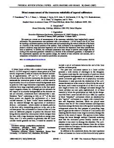
layout for. A S S E T . is s h o w n in figure 1. It is divided two sect*3 that.will take the place of the first two l o n g S - b a n d accelerator structures in the S L C linac. first section will contain the structure to b e tested. It b e installed just prior to the wakefield m e a s u r e m e n t s will b e ’r e m o v e d thereafter. In the s e c o n d section, a
Work supporud
by D e p a r t m e n t
o fE n e r g y
contract D E - A C 0 3 - 7 6 S F O O S I S .
combination chicane a n d b e a m d u m p will b e installed that will serve to d u m p the positron b u n c h while rerouting the electron b u n c h back into the linac. T h e v a c u u m c h a m b e r in this system will b e large e n o u g h to permit n o r m a l operation of both b u n c h e s in the linac w h e n the chicane m a g n e ts a r e turned off. T h e chicane will also contain a wire scanner a n d profile monitor that will b e u s e d for b e a m loading a n d single b u n c h transverse wakefield measurements. T h e details of these m e a s u r e m e n t s c a n b e f o u n d in reference 4. 2 BUNCH-TO-BUNCH
COUPLING MEASUREMENT
T h e key requirement of A S S E T is that its sensitivity to l o n g - r a n g e transverse wakefields b e such that the m e a s u r e m e n ts will yield a meaningful prediction of the p e r f o r m a n c e of a n N L C linac m a d e from the type of structure tested. T h u s the sensitivity should b e b e l o w the tolerances o n the wakefield strength in the NLC. T h e s e tolerances h a v e b e e n investigated by simulating multibunch transport for various N L C linac designs. In e a c h case, the increase in the betatron amplitudes of the b u n c h e s that occur from the w a k e field coupling a r e c o m p u t e d [l]. S i n c e this growth is a complicated function of the wakefield strength ( = W t) at the locations of the bunches, it is difficult to simply characterize the limits o n W t. However, the g e n e r a l criterion that e m e r g e s from these studies is that the condition W t < 1.0 M e V l m 2 /1 0 1 0 e at e a c h b u n c h location should b e adequate, but that a simulation of the multibunch transport using m e a s u r e m e n t s that a r e sensitive to at least a third of this strength should b e m a d e as a further check. Achieving this level of sensitivity using the S L C is n o n trivial a n d requires m a n y of the control a n d analysis techniques that h a v e b e e n d e v e l o p e d for colliding b e a m o p e r a tion. In the m e thod proposed, the positron b e a m will serve as a drive b u n c h a n d will b e injected into the linac from the transport line ( S R T L ) connecting it to the S o u th D a m p i n g Ring. T h e b u n c h will then pass through the test structure a n d enter the A S S E T b e a m d u m p . T h e electron b e a m from the North D a m p i n g Ring, which will b e injected into the linac via the N R T L at a controlled tim e after the positrons, will serve as a witness b u n c h a n d b e transported through the chicane a n d back into the linac w h e r e its betatron m o tion will b e analyzed using B e a m Position Monitors (BPMs). In preparation for the measurements, the witness a n d drive b u n c h e s will b e established with a n intensity of 5 . 1 0 9 a n d 3*1010, respectively, a n d with the m i n i m u m possible b u n c h lengths (- 0.5 m m ) . T h e wimess b u n c h will b e injected a l o n g the axis of the accelerator structure to b e tested, a n d will not b e t u n e d d u r i n g the measurements. T h e injection of the drive bunch, however, will b e varied in a step wise
P r e s e n t e d at the Xvlh International C o n f e r e n c e o n H i g h E n e r g y Accelerators ( H E A C C ’9 2 ) H a m b u r g , G e r m a n y , July 20-24, 1 9 9 2
QUADRUPOLE + BPM
/
-3mm Figure 1. Layout of the Accelerator
Structure SETup (ASSET)
manner in the vertical plane using corrector magnets in the SRTL. The betatron injection phase will remain fixed but the amplkude will be varied over the maximum range permitted by the apertures of the test structure. For each setting of the drive bunch amplitude, the BPM readings of the witness bunch downstream of the chicane will be recorded. The slope of the vertical BPM position versus -drive amplitude will be computed for each monitor and these data will then be fit to determine the betatron amplitude of the witness bunch per unit amplitude of the drive bunch, a quantity that is proportional to Wt. This procedure will then be repeated for different bunch separations- to determine the temporal dependence of the transverse wakefield.
in the SLC.
the NRTL BPM data indicates that the noise is dominated by injection jitter. Thus correcting for this jitter using the NRTL trajectory data should further reduce the noise. The choice of the number of structures to use and the drive bunch parameters was based on optimizing the signal. This was complicated by the fact that the strong short-range wakefields in the structures increase the transverse size of the drive bunch and hence limit the gain in signal that would normally be achieved by increasing the drive intensity or amplitude. To study the tradeoffs, simulations of the measurements were done for the proposed SLAC Xband structures. Six structures of 1.8 m length were assumed to be centered within 3 m spacings between quadrupoles but not powered. A lattice similar to that in the linac with a 90” phase advance and an average beta, (gmax + /3min)/2, of 6 m was used. The two possible configurations, one with a focusing quadrupole before the first structure, and one with a defocusing quadrupole before it, were each simulated. The short-range wakefields assumed were those computed for these structures, and Wt was set to 1 .O MeVlm2/1010e.
3 DESIGN CONSIDERATIONS To reduce systematic errors in the measurement of longrange wakefields with the SLC, we wanted a signal that depended only on Wt. The choice of varying the drive bunch amplitude to generate a signal is preferred in this regard to varying the transverse position of the test structures or the drive bunch intensity, for example. This choice requires that no S-band structure precede the apparatus as the wakefields generated in it would also affect the witness bunch motion. Hence the test structures need to be located at the beginning of the linac. At this location, the bunch energy is smallest, 1.15 GeV, which is an advantage from the signal-to-noise point of view but a disadvantage from the strong effect of the short-range transverse wakefields on the witness bunch motion. To minimize this effect, the witness bunch intensity and length will be made as small as possible.
Different drive bunch intensities were simulated with bunch length profiles corresponding to those obtained from full compression in the SRTL. In the simulation, the bunches were represented by a series of 41 transverse slices at uniformly spaced longitudinal positions in the range of +3 times the rms bunch length. The bunch energies were assumed to be those at the beginning of the linac but no initial energy spread within the bunch was simulated as it has little effect on the drive bunch trajectories for the cases considered. The witness bunch intensity, which one wants to be small as possible, was assumed to be 5.109 since the linac BPM resolution degrades rapidly below this intensity.
The vertical plane was chosen to do the measurements because the jitter in the transverse position and angle of the bunches at injection into the linac is generally smaller in this plane, probably as the result of the fewer bends in the transport line preceding it. This injection jitter contributes to the error on the signal measurement as does the linac BPM resolution. To measure the total noise level, data were taken in a manner similar to that described above for the -wakefield measurements but with no drive bunch or test structure. H&&e the fit values of the bctatron amplitudes reflect the noise spectrum that will be encountered when the actual measurements are made. The typical amplitude observed was -5 urn when data were taken over 20 pulses from the 30 BPMs immediately downstream of the proposed chicane location. The goodness of the fits and their match to
For each choice of drive bunch intensity, the injection amplitude was fixed and a simulation done for a full range of injection phases. At every phase, the amplitude of the witness bunch trajectory was computed at the exit of each of the six structures. These signals were then normalized to the injection amplitudes that would correspond to the onset of drive bunch loss on the structure irises upstream of the point where each signal was evaluated. As an example of the results from the simulation, figure 2 shows some of the drive bunch slice trajectories with both quadrupole configurations for I = 3*1O*O and zero injection phase. The rapid growth of the beam tail illustrates the limitation that occurs in trying in increase the signal by
2
increasing the number of structures. In fact, when the normalized witness bunch amp&tudes are computed, one sees that the signal does not grow much after the first structure. Also, the effect of the beta function is observed in that the signal is generally larger for an even number of structures when the initial quadrupole is focusing, and for an odd number of structures when it is defocusing. An example of the dependence on the number of structures is shown in figure 3 where the normalized amplitude after each structure is plotted as a function of injection phase for I = 3*1010 I I I , and the quadrupole configuration 0 3 6 9 12 15 18 giving the largest signal on averZ(m) age. The lack of a strong depenFigure 2. Vertical trajectories of seven transverse slices of a 2 lOlo particle bunch dence on the number of structhrough six unpowered X-band structures in two FODO lattices (gmax = 10.2 m) tures is also seen when such which differ by only the initial quadrupole polarity. The longitudinal slice positions comparisons are made for other are-spaced in increments of the bunch length (03, and range from +3& to -30~. drive bunch intensities in the range of 1*1010 to 4*1010. In general, for I > 2*101° and two to four structures, the limitation from the beam tail size cancels all or more of the 80 gain from an increase in intensity or in the number of structures. For a single structure, this saturation occurs at a higher intensity (= 3*1010), while for five or six structures, it occurs at a lower intensity (= l.lO*O). .a
l
. 0
30
60
90
120
150
From these results, it was decided to use only one test structure in ASSET as it will yield most of the signal achievable with more structures. Running with a drive achievable for intensity of 3*1010, which is routinely colliding beam operation, a wakefield strength of 1.0 MeVtm 2/1010e will produce a betatron amplitude of 70 pm compared to an expected noise level of c 5 pm. Thus the minimum design requirements for the structures should be easily verifiable. Also, wakefield strengths at least a factor of five times smaller should be measurable so accurate simulations of the performance of an NLC linae can be made.
180
Injection Phase (degrees) -
Structure4
Structure5 Structure6
References
0
--.w.50 -.:
- ; 60 90 120 Injection Phase (degrees)
150
[l]
K. Thompson et. al., “Wake Field Suppression Future Linear Colliders”, to be published.
[2]
K. Bane and R. Gluckstern, “The Transverse Wakefield of a Detuned X-band Accelerator Structure,” SLAC-PUB-5783 (March 1992).
[3]
Measurements of SLAC J. Wang et. al., “Wakefield Linac Structures at the Argonne AATF,” SLAC-PUB5498 (May 1991).
[4]
C. Adolphsen et. al., “Proposal for an Accelerator Structure Setup in the SLC”, to be published.
180
Figure 3. Normalized betatron amplitude of the witness bunch as a function of the drive bunch injection phase. In the top (bottom) plot, the amplitudes at the end of the first (last) three structures are shown. 3
in