MEASURING MOTOR PARAMETERS - Control Technology Corp
Recommend Documents
With a dc motor, use a dc voltmeter to measure the armature voltage. The Ke is then the voltage you read divided by the speed in rad/sec. Convert rpm to rad/sec ...
To measure the Ke of the motor, put the motor shaft in a lathe and rotate the shaft at some ... Equate Electrical Power to Mechanical Power converted to Watts.
To understand how your motor will perform with a given propeller and/or battery
pack, you need to know how to measure voltage and current in your airplane's ...
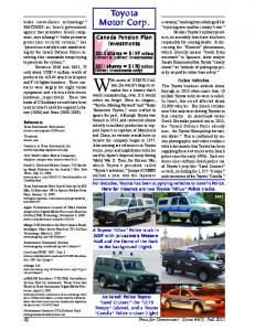
of Toyota's jeep-like “Land Cruisers” as well, including the LC75 ... e), and a
Toyota. “Corolla” Police cruiser (right) olice cruiser (right). 2001. With assets of ...
Oct 12, 2008 ... Stihl FS 40 y eléctrica. 73-01-BVM .... 3/8 x 24 FRH. 73-01-071. 73-01-031. 73-01
-111. 200. 10 x 1.50 FLH. 73-01-075 .... Stihl FS 160 / 220 / 280 / 353 / 360. 73-20
-069 ..... 405 / 415 / 450 / F 20 XE 405AT / E305 AV. ENGINE - ...
In 2016 and beyond, infrastructure reliability is more essential than ever for business continuity. The overall health o
affordable control devices that enable non-technical personnel to monitor cooking and preparation time, temperature ...
Model 2200/2200XM Controllers. TechNote ... 4300 Series ... All programs and plugin modules from the 2200/2200XM modules
file:///E|/moe/HTML/Freedman/Freedman_contents.html (1 of 2) [10/24/2003 ...
isotropy, the dynamical evolution of the Universe is specified by the .... Page 9 ...
Jun 16, 2015 - equivalent to attendance in person under ISS policy on attendance. ..... Holders have the right to receiv
Boumediène ALLAOUA, Abdellah LAOUFI, Brahim GASBAOUI, Abdessalam ABDERRAHMANI. 22 r w. Rotational speed of the DC Motor. [Rad/Sec] ex.
collaboration, and safety in human-robot interaction scenar- ios. So far, robotic research has used human motion data .... tion practices. Flash et al.
16 Jun 2015 - Toyota Motor Corp. seeks to amend its articles to create a new class of shares named "Model AA Class Share
Oct 26, 2010 - The thesis investigates on the efficiency improvement of squirrel cage ... Fuzzy Logic Controller improves the motor speed performance when ...
Feb 22, 2005 - Sea (Ostsee) or the Franconian Alp (Fränkische Schweiz) region. The rest of the regions, as well as all metropolitan areas in the study, show a ...
Feb 22, 2005 - Oliver BENDER, Kim Philip SCHUMACHER & David STEIN. Dr. Oliver Bender, Austrian Academy of Sciences, Institute for Urban and Regional ...
2University of Oviedo, Campus de Viesques, Edif. departamental 4, 33204 Gijón, Spain, ... capacity of the radio channel for wideband communications.
Speed control is the process of changing the electric power delivered to ..... controller is in general better than the PI speed controller. A future ... 2.ge-4 kg/m2.
e (V. ) Phase A. Phase B. Phase C. Voltage frequency. 49.75. 49.8. 49.85. 49.9. 49.95. 50. 50.05. 50.1. 50.15. 50.2. 12:00:00 AM 2:24:00 AM 4:48:00 AM 7:12:00 ...
3-Day Course on Brushless Motor Design, Technology, Control and Application Pune 2018.pdf. 3-Day Course on Brushless Mot
polarity change. A 2-phase motor with 12 pole pairs per stator-coil section would
thus move 48 steps per revolution or 7.5° per step. Stepper Motor Technology.
Nov 24, 2003 - they provide an accurate measurement at a low cost. Hall effect ..... used in a motor application to reduce noise. ... A more detailed analysis or.
Sep 10, 2014 - Member FINRA/SIPC. REGISTRATION FORM. Company Name: ... Please print your name and sign below if you plan
MEASURING MOTOR PARAMETERS - Control Technology Corp
1 MEASURING MOTOR PARAMETERS File: Motor parameters These are the motor parameters that are needed: Motor voltage constant Ke (volts-sec/rad)
MEASURING MOTOR PARAMETERS
File: Motor parameters
These are the motor parameters that are needed: Motor voltage constant Ke (volts-sec/rad) Motor torque constant KT (lb-in/amp) Motor resistance Ra (ohms) Motor inductance La (Henries) Motor inertia Jm (lb-in-sec^2) Load inertia reflected to the motor armature shaft Jload (lb-in-sec^2) Total inertia=Jm+Jload Jtotal(lb-in-sec^2) Note that the above values are stated for a single winding with dc motors, and are the phase values for a BLDC motor. Brushless dc motors (BLDC) are 3 phase synchronous motors used in a configuration to be treated as dc drives. MOTOR RESISTANCE For the winding resistance use an ohmmeter. For a dc motor measure the resistance between the 2 armature wires. If it is a WYE connected BLDC motor, the resistance is the line-to-line resistance. Thus divide the resistance(l-l) by 2 to get the phase resistance. MOTOR VOLTAGE CONSTANT Ke To measure the Ke of the motor, put the motor shaft in a lathe and rotate the shaft at some speed [rpm] such as 1000rpm. With a dc motor, use a dc voltmeter to measure the armature voltage. The Ke is then the voltage you read divided by the speed in rad/sec. Convert rpm to rad/sec asrev 2π radians min rad x x = rev min 60 sec sec Volts [v] Volts[v ] Ke = or speed [rad / sec] speed [rpm]
With a BLDC motor use an ac voltmeter to measure the voltage between any 2 wires of the 3 motor wires and then convert the line-to-line voltage to the phase voltage value by dividing the line-to-line voltage by 3 =1.73.
K e ( phase) =
K e (line − to − line) 1.73
MOTOR TORQUE CONSTANT KT (for a BLDC MOTOR)
The motor torque constant (KT) can be computed from the voltage constant (Ke) as-
1
lb − in K e volts( l −l ) KT = amp 0.00684 rpm
The derivation for the above equation isEquate Electrical Power to Mechanical Power converted to Watts 2π T x N x x1.356 60 12 where: T= lb-in I= Amps E= Voltsrms(line-to-line) N= rpm Rearranging terms and simplifying: 3 x E xI =
Ke =
E T = 0.00684 N I
Volts rms (l −l ) E = K e = Back emf cons tan t , N rpm T lb − in = K T = Torque cons tan t , I A
Where :
Converting rpm to rad/sec v ( l −l ) v x rev x 60 sec v x 60 Ke = = 9.554 = rad rev rad x 2π 2π x min sec min sec
Thus KT =
K e [v − sec/ rad ] 0.00684 x 9.554
v lb − in KT = 15.3 K e ( l −l ) rad amp sec
2
MOTOR TORQUE CONSTANT Kt (for a DC MOTOR)
EI =
2π T N x1.356 60 12
E I = 0.011827 N T Ke =
E T = 0.011827 N I
Ke lb − in = Therefore : K T amp 0.011827
V RPM
MOTOR INERTIA Jm
Motor rotor inertia can be measured by making an experiment. The inertia can be calculated from the equation rad Acceleration torque[lb − in] = Inertia[lb − in − sec^ 2] x acceleration sec^ 2 Also (rearranging terms) accel torque [lb − in − sec^ 2] Inertia = acceleration DC MOTORS To do this test it is necessary to measure the acceleration of the motor rotor and the acceleration torque of the motor rotor. These two parameters are described as follows: ACCELERATION – This parameter is determined by putting a step in current into the motor winding to bring the motor up to rated speed. The motor will accelerate exponentially. The acceleration is a measure of the rate of change of velocity over a period of time. To make this test, a dc tachometer should be connected to the motor shaft. The output of the tachometer should be connected to a stripchart recorder. When a step input in current is applied to the motor winding, the chart recorder will plot the rate of change of the motor shaft velocity as a function of the tachometer output voltage. The tachometer calibration can be used to convert volts to rpm. The acceleration is therefore the change in velocity for the linear part of the exponential curve divided by the time elapsed for the detected rate of change in velocity. The resulting calculation of the acceleration must have the dimensions changed to be in units of rad/sec^2. TORQUE- An ammeter must be inserted in series with the motor input winding. When the step in input current is applied to the motor input, the maximum value of current
3
should be noted. This current must be converted to torque. The torque is equal to the maximum value of current observed multiplied by the motor torque constant. Torque [lbin]= amps[a] x KT [lb-in/a]. The inertia is then the acceleration torque divided by the acceleration as stated above.
BLDC MOTORS- The tests described thus far must be modified for a bldc motor. A bldc motor must be tested with its servo amplifier. The step input will be a step in dc voltage to the servo amplifier input. The voltage step should be large enough to cause the motor to reach rated speed. With bldc motors it is not possible to measure the high frequency phase current in a WYE connected motor. Thus some other procedure must be used to measure the current or torque and velocity. Commercial bldc servo amplifiers have two dc output test points. One output is a dc voltage proportional to velocity with a given calibration. The voltage can be directly connected to a strip chart as described previously to measure the motor acceleration, A second test output provides a dc voltage proportional to torque or a percentage of rated torque. This calibrated voltage can also be recorded with a stripchart recorder to observe its maximum value for a step voltage input to the servo amplifier. The inertia can thus be calculated as done previously. MOTOR INDUCTANCE L To measure the motor inductance use a low voltage ac source to the motor winding. For a dc motor, apply the ac voltage to the armature winding. For a BLDC motor apply the ac voltage to one pair of the three wires. In both cases measure the voltage and the current. Remember that the BLDC motor is usually connected in WYE. Thus the readings will be line-to-line. You want the phase values for the voltage, so divide the voltage by 2. The impedance of the BLDC motor phase winding is thenIm pedance =
phase voltage[volts ] = [ohms ] line current[amps ]
The impedance = reacc tan ce 2 + resis tan ce 2 = [ohms]
Re ac tan ce[var s ] = impedance 2 − resis tan ce 2 Solve for the reactance from this equation. Note that the phase resistance was measured previously. The inductance can than be calculated from-
The reac tan ce [var s] = 2π x frequency x induc tan ce The frequency is probably going to be from the ac source at 60 Hz. ThusInduc tan ce[henries] =
reac tan ce[var s ] 2π x frequency[hZ ]
4
METRIC CONVERSIONS
If metric values are used, units conversions are included The equation to calculate inertia for round objects (such as the motor shaft) is-
SHAFTS,PULLEYS,GEARS ENGLISH
J = D[in]4 x LGTH[in] x 7.2 x 10-5 = [lb-in-s2] D=Diameter METRIC J = D[cm]4 x LGTH[cm] x 0.077 x 10-6 = [Kg-M2]
The equation to calculate the inertia of round hollow shafts is-
HOLLOW SHAFT-GEAR OR PULLEY ENGLISH
J = [D14 – D24] x LGTH [in] x 7.2 x 10-5 = [lb-in-sec2] D = [in] METRIC
J = [D14 – D24 ] x LGTH [cm] x 0.077 x 10-6 = [KG-M2] D= [cm] MECHANICAL TIME CONSTANT tm
With the motor constants known, you can then calculate the mechanical time constant-
tm =
∑
RL − L 2
K e( L − L ) 1.73
* KT
[sec] =
0.86
Rl − l * J total at motor K e( L − L ) * K T
5
Note that we use the phase values instead of line-to-line values. Use half the resistance line-to-line and add some resistance for the wiring from the amplifier to the motor. Usually a factor of 1.35 times the phase value of the resistance is a good approximation.
The equation to calculate the reflected inertia of a lead screw is-
LEAD SCREW METRIC
J ref =
D[cm]4 xL[cm]x0.00788[ Kg / cm3 ] = [ Kg − M 2 ] 2 16 x6366 xN
J ref =
D[cm]4 x L[cm] x 0.077 x10− 6 = [ Kg − M 2 ] 2 N
ENGLISH
J ref
D[in]4 x L[in] x 0.284[lb/in 3 ] = = [lb − in − sec2 ] 2 2 N x 16 x 246 x in
J ref =
D[in]4 x L[in] x 7.21 x 10-5 = [Lb - in - sec2 ] 2 N
The equation to calculate the reflected inertia of a rack drive is-