For implementing TOM, we use the MadWifi driver [5]. Mad-. Wifi is an open source Linux driver for wireless network devices with Atheros chipsets. The reasons ...
Measuring One-Way Delay in Wireless Mesh Networks An Experimental Investigation Barbara Staehle, Dirk Staehle Rastin Pries, Matthias Hirth∗ University of Würzburg, Germany Institute of Computer Science
{dstaehle,bstaehle,pries,hirth}@ informatik.uni-wuerzburg.de ABSTRACT Wireless Mesh networks are multi-hop networks mostly based on IEEE 802.11 technology and are considered as a viable alternative for providing broadband wireless Internet access. As a consequence, they require support for Quality of Service or advanced mechanisms for selecting Internet gateways. One important required information is the one-way delay between different nodes. In this paper, we have developed, implemented, and evaluated an one-way delay estimation technique for wireless mesh networks which is based on estimating intra node queuing an inter node forwarding delay. An IP-header option field is used to accumulate the per hop delay estimate to provide an end-to-end estimate. We also outline problems with the implementation and compare results with real one-way delays obtained from a 20 node mesh testbed. We show how estimation accuracy depends on network load and provide insights into further improvements.
1.
INTRODUCTION
Wireless Mesh Networks (WMNs) are an interesting option for extending Internet access to areas where the deployment of wireline Internet access is either impossible, more costly, or simply more cumbersome and less comfortable. The principle of WMNs is to establish access to the Internet over multiple wireless hops. A mesh client connects to a mesh router and the mesh routers form a mesh backbone consisting of wireless links which may operate on different channels. Some mesh routers are attached to the Internet via wire-line connections and are hence called mesh portals or mesh gateways. One of the key features of WMNs is self-organization in the sense that mesh clients autonomously connect to mesh routers and the mesh backbone has to adapt to mesh routers being arbitrarily switched on and off. As a consequence, routing and channel allocation should not be static but adaptive to the current environment and load situation in a much stronger way than in the wired Internet. Even in a situation when the topology in terms of mesh routers and clients remains stable, the networks load and also the ∗
this work emerged from the COST-STSM-IC0703-3940
Peter Dely, Andreas Kassler Karlstad University, Sweden Computer Science Department
{peter.dely,andreas.kassler}@kau.se
channel conditions may change on short time scales. For an optimal performance, routing protocols and resource management algorithms need to follow these changes. A key requirement for a self-optimizing mesh network is to monitor the performance of the network. Important performance parameters are packet loss, oneway delay, and available bandwidth which are interrelated in the context of WMNs. In this paper, we focus on the estimation of the one-way delay which we define as the time between entering the mesh backbone and the time when leaving it again at the mesh gateway or the last mesh router in the case of intra-mesh traffic. One obvious way to profit from one-way delay measurements would be to utilize it as a routing metric as e.g. proposed by Draves [10]. However, the performance was quite unsatisfying due to bad hop-to-hop delay measurements based on active probing, where probing packets are smaller than the normal traffic packets, for more details, see Section 2.2. Furthermore, one-way delay measurements could be used for selecting the optimal gateway for real-time applications or simply for monitoring the WMN performance. Estimating and using one-way delay measurements was proposed by Li et al. [15]. The basic idea of their Adaptive per Hop Differentiation (APHD) mechanism is to augment every packet with the delay requirement and the time spent since entering the mesh network. Every mesh router updates the already consumed time and compares it with the requirement in order to adapt the packet priority. A more elaborate description of APHD is given in Section 2.3. The main contribution of this paper are a practical implementation of one-way delay estimation in multi-hop mesh networks using an IP options field. We also demonstrate how estimation accuracy depends on network load. This is to the best of our knowledge the first implementation and experimental evaluation in a real testbed taking into account multi-hop contention. The rest of the paper is structured as follows: Section 2 gives an overview of related work by emphasizing the practical usage of one-way delay measurements, by reporting on other approaches for one-way delay measurements and the associated problems in WMNs, and finally by giving a detailed overview of APHD. Section 3 provides a description of our Tool for One-way delay Measurements (TOM) with the difficulties when actually implementing APHD and the workaround used for solving the problems. Section 4 presents a study on the accuracy of the one-way delay measurements achieved in spite of the required modifications. Finally, Section 5 summarizes the key findings of this paper.
2.
PROBLEM DESCRIPTION
The goal of this paper is that all mesh node within a WMN can estimate the one-way delay each packet experienced so far. To-
gether with a target deadline or a remaining delay budget, this information can be used to improve the performance of the WMN. In Section 2.1 we highlight why this problem is of major interest for practical mesh networking. Existing approaches of measuring the one-way delay are presented in Section 2.2, before we give an short overview of APHD which strongly inspired our work in Section 2.3.
2.1
On the Importance of One-Way Delay Measurements
Information about packet delays is vital in WMNs and can serve different purposes. As an example, having one-way delay information within Route Request messages, the receiver would have a better knowledge of path qualities and could select a path with the lowest delay. In a similar way, such information could be used by gateway selection protocols or mechanisms trying to guarantee Quality of Service (QoS). Finally, it has to be ensured that the delay requirements of real-time applications like VoIP or video streaming are met, while best effort traffic is also forwarded within acceptable time bounds. A proactive delay assurance approach has e.g. been presented by Cordeiro et al. [9]. In a simulation study, the authors used the methodology of AdHoc Probe [17] to obtain the one-way delay on each link. This information was used as a link metric for Optimized Link State Routing (OLSR). The proposed protocol OLSR Minimum Delay (OLSR-MD) was compared against OLSR with the standard hop count and a minimum loss metric. The results demonstrate that the minimum delay metric performs best in terms of average packet loss probability. An analysis of the throughput and per-flow delay reveals however that OLSR-MD results in low throughput and high delay for nearly half of all flows. This is simply due to the fact that the one-way delays which are the base for the MD routing metric are determined with small probe packets before setting up the routing topology and do not take traffic characteristics into account. It may thus happen that, if no other traffic is present in the network, the probes sent on a link experience a very small delay, but larger data packets sent on this link may experience higher delay or retransmission due to congestion. OLSR-MD is an interesting approach towards mesh routing with delay assurance, but the computation and maintenance of the link metrics have to be improved for implementing OLSR-MD in a real-world environment. etwas sehr lang das eine Paper diskutiert APHD which was introduced by Li et al. [15] is an example for a reactive delay assurance solution. As the idea for obtaining the endto-end delay is the base of our implementation efforts, we introduce the APHD in detail in Section 2.3.
2.2
Measuring the One-Way Delay
For measuring a wireless path’s delay, two simple ideas which are also widely spread in the wired world seem reasonable. One could either add Timestamps (TS) to each packet and subtract the reception from the transmission time or use a probe packet’s Round Trip Time (RTT) divided by two as the one-way delay. A more sophisticated concept called Packet Pair (PP) was proposed by Keshav [14]. The basic idea is that if two packets are sent directly after each other, they are also queued one after the other and the time which lies between the end of the reception of the first packet and the start of the reception of the second packet, the dispersion, is the transmission time. If timestamps can be added to a packet directly before it is transmitted, the TS method allows to determine the packet delay very easily and accurately without generating additional measurement overhead. The downside of this method is that the clocks of the
stations have to be synchronized which is a challenge for any realworld implementation, as hardware clocks are in general neither synchronized nor equally fast. Clocks can be synchronized via the Network Time Protocol (NTP) or GPS, but both methods are more suitable for test bed setups than in a productive indoor environment. The RTT method does not need synchronized clocks, as the sender of a probe does only need to record the time until the packet returns and obtains a one-way delay of OWD = RTT/2. Especially in a wireless environment, this method has several disadvantages: it first assumes that the receiver of the probe can immediately answer and that the links are symmetric. Thus, it is not appropriate for an exact measurement of one-way delay in wireless networks with asymmetric links and interfering traffic. Especially in multichannel networks like the KAUMesh test bed [4], where channel switches are needed in order to send packets to different neighbors, the delays on forward and backward path can be very different. Secondly, significant additional measurement traffic has to be generated for up to date measurements. Probing packets are thirdly rather small, such that the measurements may underestimate the delay of larger payload packets. Fourthly, the delay information is only available at the node which triggers the measurement, i.e. the measurement packets are of no use for forwarding or destination nodes. In general, delay measurement in wireless networks with RTTs is more challenging than in wired networks, as the unpredictable behavior of the MAC layer heavily disturbs transmission times. Malone et al. [16] showed for instance that it is not possible to directly infer the queue length from the RTT. Several experiments demonstrated that due to the random nature of the WiFi MAC protocol, the RTT is correlated with the buffer occupancy, but there is significant noise which increases with the queue length. The packet pair concept has been widely applied in wired and wireless networks. Kapoor et al. [13] used e.g. the dispersion between packet pairs of equal length for implementing CapProbe, a tool which estimates the link bandwidth. While the idea worked well in simulations, experimental studies showed that the estimator is only good in lightly loaded networks with wired and last-hop wireless links. As soon as the network suffers congestion, the estimator does not produce reasonable results. Sun et al. [17] used CapProbe as an inspiration for AdHoc Probe, a path capacity estimation tool specially designed for the multi-hop ad-hoc wireless environment. In contrast to CapProbe, which attempts to estimate the bottleneck link capacity, AdHoc Probe aims at estimating the end-to-end path rate based on one-way delay measurements. The authors propose to obtain the one-way delay of a link by sending a number of packet pairs. The delay of the link is obtained as the dispersion between the packet pair with the smallest oneway delay sum, as this pair is assumed to have suffered the least amount of congestion. AdHoc Probe has been implemented in a 802.11b testbed and problems concerning auto rate adaptation schemes, clock drifts, and clock skewness had to be handled. All in all, the authors conclude that AdHoc Probe is suitable for bandwidth estimation in ad hoc networks. No results are given on the accuracy of the one-way delay measurements alone. Note moreover that this idea is not suitable if one aims at estimating the current network performance using one-way delays. An experimental study using both RTT and PP for estimating the link quality has been presented by Draves et al. [10]. The authors used a wireless testbed in order to compare the performance of RTT and PP when used as link quality routing metrics against the performance of the link metrics Expected Transmission Count (ETX) and hop count. The results showed that only ETX was able to outperform the hop count metric, whereas the two delay based metrics performed poorly. In this study each node periodically sends probes
to each of its neighbors which in turn immediately acknowledges the probes to the original node that is now able to compute the RTT metric. For obtaining the second delay metric, PP, each node periodically sends two probe packets to each neighbor. The neighbor sends the packet dispersion back to the sender. In both cases, the measured durations are used to calculate the metric of this link as exponential weighted moving average and reported to the routing layer. No results on the accuracy of the measurements were published, but both techniques tend to be inaccurate due to queuing delays, congestion or retransmissions. Moreover, both methods introduce a significant overhead and suffer from self-interference. In a follow-up study [11] the authors therefore proposed to use the Expected Transmission Time (ETT) as routing metric instead. ETT is not obtained by delay measurements, but estimated as a product of the ETX and the fraction of packet length and link data rate. All solutions summarized in this section suffer from one or several of the following draw backs: Probe packets cause additional overhead, are smaller than normal payload packets, and are sent at intervals not correlated to the payload traffic on the channel. This makes them unsuitable for a real-time measurement of the delay experienced by the payload packets. Methods using timestamps suffer from problems with clock drifts or clock skewness. Approaches using the round trip time fail to give good one-way delay estimations in networks with asymmetric links. In the next section we will therefore introduce an algorithm which promises to solve many of those problems. in dieser related work section kann auch noch gekuerzt werden, wenn noetig
2.3
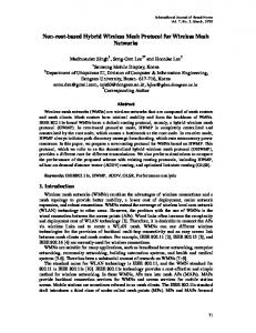
where pl is the packet length and r the used data rate which is assumed to be known when the transmission starts. As depicted in Figure 1, B updates the delay so far (dsf) field of p to dsf = dsf + tB + tBC
(3)
before sending the packet to C. Additionally, the hops so far field is increased. A requirement for the approach is to set the dsf field in the packet as late as possible since otherwise the transmission delay is not exactly known. In fact, the dsf field should be set just before the node is actually accessing the channel which means after the backoff phase. We will later see that modifying a packet at that instant of time is hardly possible in praxis.
figures/delayestimation.pdf
APHD
IEEE 802.11e is an approved amendment to the IEEE 802.11 standard and has been incorporated in the IEEE 802.11-2007 standard [12]. 802.11e defines a set of MAC layer QoS enhancements for supporting delay-sensitive applications, such as VoIP or Multimedia Streaming. This is achieved by the Enhanced Distributed Channel Access (EDCA) mechanism which enables service differentiation by introducing four different priority queues with different backoff parameters. APHD, which was proposed by Li et al. [15] uses 802.11e based channel access to assure end-to-end delay requirements in wireless multi hop networks. The basic idea of APHD is to estimate the delay that each packet has experienced so far on a multi-hop path at each intermediate link, depending on the target delay, and the delay experienced so far in the mesh, temporarily adapt the priority of the packet. As an example, if the delay experienced so far is very close to the target delay and still some hops to be forwarded, the priority can be increased for the next hop. Each packet is extended by four MAC layer header fields. The fields "e2e delay requirement" and "e2e hops" are set by the sender of a packet and specify the time and the hops within which the packet shall be delivered. The "delay so far" and "hops so far" fields are updated by every forwarding node. To update a packet’s delay so far field, a combination of measurements and estimation is used which we visualize in Figure 1. If, at time ti (B) packet p is received by the MAC layer of node B, a node internal timestamp is recorded. Another local timestamp is generated, when B accesses the channel to transmit the packet, i.e. at time to (B). The intra node delay can be computed as tB = to (B) − ti (B).
(1)
To avoid problems with drifting clocks, the inter node delay required for a transmission between B and its next hop C, tBC , is not measured by node C, but estimated by node B as tBC = pl /r
(2)
Figure 1: APHD: Intra and inter node delay Each forwarding node running APHD compares the information on delay requirements with the already accumulated value. Based on this analysis and the channel contention state, the node dynamically adjusts the packet’s priority level in order to send already delayed packets faster than not-delayed packets. In a simulation study, the authors demonstrated that APHD is suitable for guaranteeing end-to-end delay requirements and increasing the network capacity. APHD has however never been implemented on real hardware and the authors could thus not indicate how well the delay estimation approach matches reality. In the following, we describe our contributions for realizing this task and elaborate the difficulties that occur when implementing the concept on real nodes.
3.
IMPLEMENTING TOM
In order to find out which accuracy is achievable for APHD like one-way delay measurements when introducing only a small overhead, we implemented a tool for one-way-delay measurements, TOM for short. dieser satz ist kaum zu verstehen Our goal is to find out whether we obtain a precision and timeliness which is suitable for packet scheduling decisions like in APHD or rather for routing or resource management decisions which take place on larger time scales and require less timeliness. Results of our inquiry can be found in Section 4. In the following we describe how we use two APHD ideas for implementing TOM. Firstly, we estimate the one-way delay of a packet as the sum of intra and inter node delay. Secondly, each data packet carries delay information in its IP
option fields for making it immediately available and avoid additional measurement overhead through e.g. active probing. In fact, the overhead induced by a larger packet is much less than the one induced by an additional packet since no additional MAC headers and no additional channel access is required which are more critical in 802.11 networks than the pure data transmission. Finally, we have implemented a flexible mechanism which allows to specify which flows should carry such one-way delay estimates (such as just routing packets, VoIP packets, or TCP packets). In the following we describe how we implemented TOM on the nodes of the KAUMesh, a multi-radio multi-channel mesh testbed at the Karlstad University [4]. kann bei Bedarf gekuerzt werden In theory, the first task, i.e. estimating a packet’s transmission delay as the sum of intra and inter node delays, like shown in Figure 1, is simple. In practice, this task is non-trivial, as the in- and out-time of a packet at a node have to be recorded. Retrieving the time ti (B) when a packet is received by node B at MAC layer is not a problem, as this information can be retrieved from the MadWifi driver [5]. Getting the time when a packet is sent out, to (B), is more challenging. In Section 3.1 we describe how we solved this issue. The second task, embedding the delay information into packets has to be transparent to the application generating the packet and to other nodes which do not run TOM. Furthermore, it has to minimize the overhead. The method used for APHD, adding four additional fields to an existing packet header [15], fails to meet both requirements: all machines not running APHD are not able to interpret the additional header fields and are thus not able to process the modified packets payload. Moreover, the four header fields carry information which are not required for one-way delay measurements and are quite large. In Section 3.2 we describe our lightweight approach which is also tolerated by machines not running TOM.
cise prediction of the delay we furthermore decided to make some very small modifications to the open source network card driver MadWifi which we describe in Section 3.1.3.
3.1.1
Linux Netfilter
Netfilter is a framework for packet filtering inside the Linux 2.4.x and 2.6.x kernel series. In depth details can be found on the project’s homepage [7], we only summarize some ideas. The netfilter features which we use in our work, the so called "hooks" are well-defined points a packet traversing a networking protocol stack will pass. IPv4 for instance defines 5 hooks which are shown in Figure 2. If a packet passes a hook, the protocol calls netfilter using both the packet and the hook number. Kernel functions can register to listen to different hooks. When a packet is passed to the netfilter framework, any function which has registered for that protocol and hook gets the chance to perform tasks like examining, modifying, or discarding the packet.
figures/netfilter.pdf
Figure 2: Linux netfilter IPv4 hooks
3.1
Estimating the Transmission Delay
An ideal one-way delay measurement tool should run on all hardand software and should guarantee a precise delay estimation. For an implementation of the delay estimation as depicted in Figure 1 these two goals are conflicting. Information on when a packet is sent and at which transmission rate can only be gathered within the network card driver. Major modifications of an existing driver or implementing an own network card driver would provide those information, but also limit the tool portability. Even if possible from an implementation point of view, there is still the question whether adding a timestamp to a packet just in the moment when the access to the wireless channel is granted would be possible from a technical point of view since even a small additional delay for setting the timestamp might cause synchronization problems in the physical layer. Implementing TOM in the user space would make the tool hardware independent, but not give the possibility to monitor packets which do not pass the user space but are only forwarded by the IP layer. Moreover, a user space program has no access to the used data rate and can record the last timestamp only after having passed the packet to the kernel. We decided to cope with this trade-off between portability and precision by slightly modifying the algorithm how inter and intra node delay are obtained. We describe our estimation algorithm in Section 3.1.4. The measurement and packet modification routines are realized as hard- and software independent Linux kernel modules, the measurement and shared module. The measurement module relies strongly on the Linux netfilter IPv4 hooks whereof we summarize the key properties in Section 3.1.1 before we describe the modules more closely in Section 3.1.2. To achieve a more pre-
The five available hooks for IPv4 which we used for TOM are located at different positions within the network stack, as it can be seen in Figure 2. The NF_IP_PREROUTING hook is passed by all packets delivered by the network device driver, before any further routing decisions are done. After an analysis of the packets destination address, the routing algorithm decides, whether the packet has to be sent to a local process or to an outgoing interface. Every packet going to the user space passes the NF_IP_LOCAL_IN hook, and the NF_IP_FORWARDING hook is passed by every packet forwarded to another node. Locally generated packets pass the NF_IP_LOCAL_OUT hook. Afterwards, those packets join the forwarded packets for passing the NF_IP_POSTROUTING hook, before they are handed over to the network card driver. Not all packets pass all hooks. Observe however that each packet traversing the IPv4 stack will pass one hook at the connection to the user space and at the border to the link layer. These are the points where the measurement module registers with suitable callback functions.
3.1.2
The TOM Kernel Modules
Linux kernel modules can be easily integrated into a running system, as they can be loaded into the kernel on demand and provide their functionality without the need of rebooting or recompiling. Our modules have this flexibility and are moreover completely independent from the underlying hard- and software. The shared module is a function library which is the heart of TOM. It provides all functions which are needed for recording and storing timestamps, computing the delays and estimators, and modifying the delay information carried by each packet. The measure-
ment module uses the callback functions provided by the netfilter hooks to call the appropriate functions from the shared module. In the case of the NF_IP_PREROUTING or the NF_IP_LOCAL_OUT hook, the shared module is responsible for recording a timestamp. If a packet passes the NF_IP_POSTROUTING hook, a shared module function updates the delay information carried by the packet.
figures/delayestimationTOM.pdf
3.1.3
Modifications of the MadWifi Driver
For implementing TOM, we use the MadWifi driver [5]. MadWifi is an open source Linux driver for wireless network devices with Atheros chipsets. The reasons for choosing MadWifi are that it allows us to make more precise measurements by adding two calls for shared module functions which record timestamps and update the packet information. Moreover, the internal data structure was extended to save timestamps. TOM will thus not run with the unmodified MadWifi driver, but it is easy to port these small modifications to any other system. MadWifi is open source, but one key component, the Hardware Abstraction Layer (HAL) was available in binary only at the time of the implementation and could thus not be changed. The HAL can be imagined as a black box, where all direct access to the Atheros hardware is routed through. It can be seen as wrapper around the hardware registers and prevents the user from tuning the card to frequencies or transmission powers which violate regulatory restrictions.
3.1.4
Intra and Inter Node Delay Derivation
For our implementation, the lack of HAL source is an additional challenge: packets can only be accessed as long as they have not been handed over to the HAL methods. As discussed, it is doubtful whether this would be a valid approach even when possible from a pure implementation point of view. Hence, exactly implementing the ideas proposed for APHD is not suitable, as it is not possible to exactly determine the time to (B) when the card of node B captures the channel to transmit the packet. To solve this problem, we slightly modify the definitions of intra and inter node delay as depicted in Figure 3. As we can access the packet the last time before it is handed over to the HAL, i.e at time
tm (B) = to (B) − δ.
(4)
Figure 3: TOM: Intra and inter node delay δ denotes the queuing and random access delay which occurs on the networking and MAC layer and which is unknown at time tm (B). We therefore alter the definition of the inter node delay t0BC = δ + ttx ,
(6)
where ttx denotes the time which is required for transmitting the packet to the next hop C. Recall that in APHD ttx is estimated as the fraction of packet length and link data rate. To make our estimation of one-way delays more exact and to incorporate the queuing delay while still avoiding clock drift problems, we use a different approach. The HAL does not notify the MadWifi driver when the packet is sent, but only when the acknowledgment for the transmitted packet is received. We thus obtain an estimate for t0BC as the time between tm (B) and the time when the acknowledgment for the packet returns. As acknowledgments are small, this is an insignificant measurement error.weshalb zieht man die Zeit denn nicht ab, da die Ack Groesse doch konstant ist und deren uebertragungsgeschwindigkeit ebenso The problem is of course that when packet p enters the queue, no estimation for t0BC which will actually be experienced by p is available. We assume that the delay which will be experienced by packet p will be similar to the delay experienced by its predecessors. Therefore, an exponentially weighted moving average of the previous packets accumulated inter node delays, tˆ0 BC , is used to estimate the transmission delay. When receiving an ACK, the estimator of the inter node delay is updated to tˆ0 BC = w · tˆ0 BC + (1 − w) · t0BC
(7)
where the smoothing factor w is set to 0.5 in the measurement studies. Before forwarding a packet to the HAL, the end-to-end delay requirement (edr) field is set to edr = edr − [tˆ0 BC + (ti (B) − tm (B))]. We derive the intra node delay of packet p at node B as
t0B = tm (B) − ti (B).
(5)
(8)
What makes the estimation of one-way delay even more complicated is the fact that if packets p, q, r are passed directly after another to MadWifi, the delay information of packet q is presumably not available if packet r is passed to the HAL as it is still in the hardware queue. This means that the one-way delay estimation which is embedded into packet r does not incorporate the transmission
delay experienced by packet q, but only the delay experienced by packet p and its predecessors. We would like to point out that the sources of error we listed in this section are the price we pay for the flexibility and ease of transportation of TOM. Using the freely available open source MadWifi driver makes our tool portable to a large number of systems, but restricts the points where the packets can be modified due to the black box HAL. Recently, the HAL source code has been published [5]. Future implementation work will thus be dedicated to making the one-way delay estimations more precise by using HAL methods.
3.2
Embedding Delay Information
To avoid additional probe packets or signaling traffic, every payload packet has to carry its own delay information. The most trivial solution for this problem is to add an extra header between the IP header and the header of the next higher layer which contains the required information, as it is done for example in the AODVUU implementation [1]. The next obvious method is adding extra fields to an already existing protocol header, as e.g. proposed for APHD [15]. The major drawbacks of both solutions is that they are not transparent to nodes not running the measurement tool. That means, if node A runs the tool and B does not, these nodes cannot communicate, because each packet sent by A is encapsulated with a new header or carries additional header fields which can not be understood by B. To overcome this problem, TOM uses IP option fields to store the delay information. If a node receives a packet with an unknown IP option, the option data will be ignored but the packet data is processed normally [3]. Using IP options thus facilitates integrating TOM in an existing network. It is possible that only some of the nodes are equipped with the measuring software, but are still able to communicate with the rest of the test bed. If a packet is sent along a path where some nodes run TOM and some do not, the delay information will not be updated and is consequently wrong. For a setup with a purely wireless testbed where all nodes are remotely administrated via the same wireless LAN interface which is also used for the delay measurements, this is however advantageous. A measurement tool adding a supplementary header to all payload traffic sent by the nodes would make remote administration impossible without installing the measurement tool also on the management server. In contrast to the original APHD design, our proposal adds moreover only one supplementary header (which is coded as an IP option) to the packets. This allows to minimize the additional overhead while we are still capable of measuring the one-way delay. Out of the fields proposed by [15], we only use the edr field. As depicted in Figure 3, each node which forwards the packet updates this field by subtracting the measured intra node delay and the estimated inter node delay. If delay measurements are required, the field is initialized with a constant value c which allows to obtain the estimated delay at each time as c − edr. In Figure 3, edr is initialized to c = 100 ms. If a functionality similar to APHD is required, the the edr field is initially set to the target delay which should not be violated. weshalb haben wir den delay auf 100 ms gesetzt? Welche Vorgaben (ITU,...) haben wir dabei betrachtet?
4.
802.11 b/g access network of the university.
EXPERIMENTAL EVALUATION
figures/topology_grosse_nummern-4.pdf
Figure 4: KAUMesh topology To determine the quality of the one-way delay estimations obtained by TOM, we considered scenarios with varying number of hops and traffic intensities. Both the measured and the interfering traffic are generated using the Multi-Generator (MGEN) [6]. MGEN is an open source toolset which generates real-time traffic patterns for IP performance tests and generates packets with timestamps. We use those timestamps as a simple method for obtaining reference one-way delay measurements. Drifting and asynchronous clocks are the major danger for this method, therefore continuous NTP updates using the wired administration backbone of the KAUMesh are performed. The MGEN traces are analyzed with the open source tool TRPR[8] to gain reference values for the packet one-way delays. During all tests, the packet size is set to 1000 Bytes. Due to the different methodology, the one-way delays obtained by MGEN and TOM vary in several aspects. For a better understanding, we introduce some terms used during the discussion of the measurement results. The term offset refers to the difference between the packet delay measured by MGEN and the delay measured by TOM. The term spike is used for delays noticeably higher than the average delay, whereas peak is used for extremely high delays of single packets, which are several times larger than the spikes. If the delay curve of TOM shows the same trend as the delay curve of MGEN but both curves are out of sync, we refer to the difference as shift. For obtaining numerical results, we consider three increasingly complex test setups: firstly, we analyze the single hop case without interfering cross traffic. Afterwards, we consider delay estimations obtained in a single hop setting with cross traffic of varying intensity. Finally, we examine the quality of delay estimations in the multi-hop case.
4.1
Single Hop, no Cross Traffic
For a first investigation of the one-way delay estimation accuracy we use a simple setup. During 100 seconds, node 7 generAs already mentioned earlier, we implemented and evaluated ates 50, 100, and 200 packets per second and sends them to node TOM in the KAUMesh [4] testbed, whereof a network map is depicted in Figure 4. The testbed includes fourteen Cambria GW2358-4 [2] 10. No other nodes are interfering. Figure 5 shows all packet delays obtained from the experiments with 100 packets per second. nodes running Linux with a customized kernel version 2.6.22.2 deWe show results for all considered 10000 packets, but for sakes of ployed within the lecture building. The mesh backbone is built readability limit the y-axis to 15 ms, as the MGEN traces contained using IEEE 802.11a to avoid disturbances from the wireless IEEE
some peaks over 100 ms which were not observed by TOM. In the following we discuss this issue and the offset between MGEN and TOM delays.
figures/sHopNoJam_new.pdf
the one-way delay in kernel space, while MGEN measures the delay in user space, we assume that this method includes the transition times from the user space to the network interface. Our kernel modules operate below the user space and enable thus a more accurate characterization of the networking layer. In order to make the offset better visible, Figure 5(b) shows histograms of the oneway delays obtained by MGEN and TOM. TOM produces a peak at about 1.75 ms and MGEN at about 2.25 ms. The peak of TOM is concentrated on one 50 µs bin with around 80% of the packet, while the peak of MGEN is a little more dispersed and two 50 µs bins cover a little more 80% of the values. The distribution of the values above the peaks looks also a little different. While the frequency of packets is roughly geometrically decreasing with an increasing delay for TOM, there is a smaller peak around 2.4 ms for MGEN. Values above 2 ms for TOM or 2.5 ms for MGEN do not occur with significant frequency.
(a) all packets
figures/sHopNoJamMagbs.pdf
figures/sHopNoJam_hist.pdf
(a) zoom level 1
(b) histogram of one-way delays Figure 5: Single hop one-way delays, no cross traffic The height of the peaks which could not be fully shown is between 48ms and 140 ms. They were found in every measurement performed during the evaluation, independent of the used sending packet rate and the receiving node. Furthermore, a certain pattern can be observed. In all experiments, the first peak can be found about 30 s after the measurement starts which corresponds to 3000 packets in Figure 5(a). After a short period without peaks, peaks of lower height, but still far above the mean delay appear periodically. A clock synchronization problem can be excluded, because the synchronization period is smaller than the period of the peaks. Noticeable is also the fact that TOM does not show the peaks. As TOM is located in the kernel space, whereas MGEN is a user space program, it might be connected to the programs schedule, but we were not able to find a final explanation. Debugging MGEN is not our goal, we therefore ignore the peaks in the further discussion and deal with them as measurement errors. The second point which is noticeable concerning the results is a constant offset of roughly 0.5 ms between the delays measured by MGEN and the delays measured by TOM. This offset is the same for all runs we executed for the one hop experiment and independent of the number of packets sent per second. As TOM measures
figures/sHopNoJamzoom_max.pdf
(b) zoom level 2 Figure 6: Single hop one-way delays, no cross traffic (zoom) Figure 6(a) shows the delays measured for the packets number 750 to 1350 of the experiment already visualized in Figure 5(a). We added a correction term of 0.5 ms to each measured by TOM to discuss two aspects which were less clear in Figure 5. Observe that the mean MGEN and the mean corrected TOM delay are approximately the same. This allows to see that firstly, the MGEN delays are suffering from clock drifts and that secondly, the spikes in the MGEN measurements are larger than in the TOM measurements.
A closer look at the curve depicting the one-way delays obtained from the MGEN traces illustrates the inherent problem of measurements using timestamps. The delays are slightly increasing for about 300 packets, then suddenly decrease by roughly 0.06 ms and start increasing again. This pattern repeats throughout the experiment and is simply related to the NTP updates which are performed every three seconds, or every 300 packets in this case respectively. This sub structure could be observed in every run and independent of the number of packets sent per second. In contrast, the measured TOM delays do not suffer from such synchronization problems. An NTP update every 3 seconds is not imaginable in a purely wireless environment and also the accuracy of the NTP update would suffer from the variability in the delay of multi-hop wireless transmissions. Figure 6(a) gives thus only a weak impression on the errors due to clock drift which would sum up in a less frequently synchronized setting. The reason why the spikes reported by TOM are only half the height of the MGEN spikes and shifted by one packet is due to the exponential moving average which is used for estimating the inter node delay. Furthermore, the delay estimation is used for the next packet, which results in the fact that the curve of TOM is shifted by one packet to MGEN.This can be best observed in Figure 6(b) that shows two peaks on a per packet level. The two peaks are seen by TOM with a shift of one packet and only one half. Since after the peaks the following one-way delays are constant again, the peak flattens geometrically. Here, the 0.5 ms offset is also nicely visible when comparing the minimum one-way delays.
4.2
MGEN and the TOM delays is also one packet and again the delay spikes have only the half height due the moving average approximation. As before, the effect of resynchronizing the clocks is visible at packet number 1150. Figure 7 visualizes however also a downside of our approach which has not been discussed earlier. As we use an exponential weighted moving average for the inter node delay estimation, a spike affects the immediate delay estimation to a smaller degree, but in turn heavily impacts the delay estimations of the succeeding packets. This is a problem if accurate delay information for each packet are required. If however, the one-way delays are needed for routing or QoE ensuring mechanisms, than a less oscillating measurement as it is obtained by TOM is more advantageous.
4.3
Multi-Hop
Finally, the performance of TOM is investigated in a multi-hop environment. The measurement traffic is again generated at node 7 with a fixed packet size of 1000 Bytes at rates of 50, 100, and 200 packets per second. The destination varies between node 10, 11, and 14 to examine the delay estimations for one, two, or three hops. The disturbing flow between node 15 and node 21 is sent at rates between 0 and 140 packets per second.
Single Hop and Cross Traffic
To evaluate TOM in a more realistic scenario, we use the test setup as described above, but add an interfering traffic flow between node 15 and node 21. The size of the packets in this cross traffic flow is also set to 1000 Bytes and its rate is set to 140 packets per second.
figures/mHopJamMag_v03_bs.pdf
Figure 8: Three hop one-way delays and cross traffic figures/sHopJamMag_v03_bs.pdf
Figure 7: Single hop one-way delays and cross traffic Figure 7 shows the packet delays obtained for the packets 1050 to 1250 from a measurement with node 7 sending 200 packets per second and node 15 sending 140 interfering packets per second. Observe first that the one-way delays obtained from both methods are varying more strongly than for the setting where no interfering traffic. This is an indicator for the congestion on the channel and is captured to a similar degree by both TOM and MGEN. As in the simpler experiment visualized in Figure 5 and Figure 6, the offset between both tools is about 0.5 ms. The shift between the
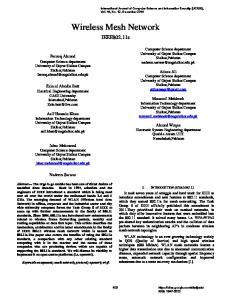
Figure 8 shows a part of a measurement run where node 7 is sending 200 packets per second to node 14, i.e. over 3 hops with a cross traffic intensity of 80 packets of 1 kB per second. Again, the delay estimation of TOM is shifted in time compared to the shown MGEN delays. This time, the shift is however larger than one packet. This is caused by several facts. Due to the increased channel contention, queuing delays and MAC layer retransmissions accumulate. This has the effect that the acknowledgment of the immediately preceding packet is frequently not yet received when a packet’s inter node delay is estimated. Consequently, this estimation has to work with the information of the older packets. We identified the same problem in the single hop case, but this time the problem is more severe. In the single hop scenario, node 7 competed only with node 23 for the wireless medium. Now, node 7 has to share the channel access time with node 23 and node 10. Another effect of an increasing degree of channel contention are higher and more variant queuing delays and MAC layer retransmissions which can not be measured exactly by TOM but have to be estimated. If the contention delay is highly variant, the assumption that a packet suffers the same queuing delays as its predecessors and successors does not always hold, which introduces an error in
comparison to the MGEN method. The higher variance of the contention delay has also a negative influence on the offset of the moving average estimation. As the delay values are oscillating faster than in the previous experiments, the spike flattening effect of the moving average method increases the offset between the MGEN and TOM estimations. Next, a packet traveling from node 7 to node 14 is queued at the source and at each intermediate hop, i.e. three times instead of one time in the single hop case. Consequently, the shift between the measured delay using MGEN and the estimated delays using TOM is increasing. However, one of the key conclusions from Figure 8 is that TOM is able to follow the larger scale variations in the one-way delay. Consequently, making scheduling decision based on the one-way delays stored in a packet does not seem feasible with the TOM implementation. However, using one-way delay measurements obtained by TOM e.g. in routing metric or for selecting optimal gateways seems to be possible.kann gekuerzt werden, ziemlich viel bla bla The latter way of utilizing one-way delay measurements requires a good estimation of the one-way delay average of medium time scales in the order of hundreds of milliseconds. Therefore, we now investigate the capability of TOM to correctly measure the average one-way delay in a series of packets by comparing it with the average one-way delay measurements observed by MGEN. Figure 9 visualizes the average differences between the one-way delays measured by MGEN and the one-way delays estimated by TOM. The results were obtained from experiments with different hop counts and varying cross traffic intensities. For each experiment, the mean value of all offsets obtained during the experiment is recorded. The bars of each group show the mean offset averaged over five runs for one specific cross traffic intensity. The average delay differences vary only weakly among the experiments, confidence intervals are therefore omitted. The mapping between colors and cross traffic intensity is shown on the right. Each subfigure shows a different amount of measurement traffic. Within one subfigure we show results for a varying number of hops and a cross traffic strength between 0 and 140 packets per second. Observe that the difference between TOM estimations and MGEN measurements is always above 0.5 ms, which we identified as delay between user space and kernel space. TOM additionally underestimates the average delay measured by MGEN, as this method shows peaks which are not shown by TOM. These peaks increase the delay measured by MGEN by a non negligible amount, as they are up to 90 times bigger than the average delay. Further, the delay spikes measured by the tool are flattened due to averaging the values. This also leads to an underestimation of the delay which is especially severe for highly varying delays. Interestingly, for medium traffic intensities depicted in Figure 9(a) and Figure 9(b), the delay variation is almost independent of the hop count and the disturbing traffic. As a result, the offset between the delays estimated by TOM and the delays measured by MGEN is nearly constant for every hop count and disturbing traffic. Consequently, the difference of the mean delays is also constant. At a measurement traffic of 200 packets per second, the variation of the delays increases with the amount of cross traffic if all packets have to traverse three hops. In this case the delay estimation of TOM looses accuracy as the queuing delay is increasing and highly variant. Consequently, the difference between the mean delays of the tool and MGEN increases as illustrated by Figure 9(c). We would like to point out that the results of the error analysis shown in Figure 9 are conform to results known from literature. With an increasing degree of channel contention and hop count, delay estimations become more challenging. For TOM this is the price of flexibility we pay, as we decided for portability reasons to
use MadWifi with the HAL as built-in black box.
5.
CONCLUSION
In this paper, we presented a robust and lightweight approach for measuring the one-way delay in wireless networks, which we called TOM. In contrast to other approaches in this field, neither clock synchronization nor additional measurement traffic is required and the delay estimation also works for asymmetric links. Using a number of open source building blocks, we implemented TOM in an IEEE 802.11-based wireless mesh network. Experimental results demonstrated that the one-way delay estimations provided by TOM are pretty accurate in normal load scenarios and still capture the path delay behavior in highly loaded multi-hop environments. We found that TOM may deliver valuable information for routing, admission control, or gateway selection algorithms. However, TOM is currently not able to provide measurements of a precision and timeliness to be useful for an APHD like packet scheduling. From the experiments we conclude that the principle idea of measuring the one-way delay by embedding the accumulated per hop delay into the data packets using IP header option is very promising. The estimation of the inter-node delays, however, should be improved (a) by moving the time when updating the delay information in the packet closer to the time when it is actually scheduled or (b) by a more sophisticed estimation algorithm. Also, the goal of the current implementation was on reproducing the idea of APHD. The future development of TOM will shift towards improving the one-way delay estimates on a medium time scale which was not the primary goal so far.
6.
REFERENCES
[1] AODV-UU. http://core.it.uu.se/core/index.php/AODV-UU. [2] Gateworks, Cambria GW2358-4. http://www.gateworks.com/products/cambria/datasheets/ gw2358-4ds.pdf. [3] Internet Protocol Specifications, RFC 791. [4] KAUmesh. http://www.cs.kau.se/cs/prtp/pmwiki/pmwiki.php? n=Resources.MeshTestbed. [5] Madwifi Project. http://madwifi-project.org. [6] Multi-Generator. http://cs.itd.nrl.navy.mil/work/mgen/. [7] The netfilter.org project. http://www.netfilter.org/. [8] TRace Plot Real-time. http://pf.itd.nrl.navy.mil/protools/trpr.html. [9] W. Cordeiro, E. Aguiar, W. Moreira, A. Abelem, and M. Stanton. Providing Quality of Service for Mesh Networks Using Link Delay Measurements. In ICCCN’07, Honolulu, HI, USA, August 2007. [10] R. Draves, J. Padhye, and B. Zill. Comparison of Routing Metrics for Static Multi-Hop Wireless Networks. In SIGCOMM ’04, Portland, Oregon, USA, September 2004. [11] R. Draves, J. Padhye, and B. Zill. Routing in Multi-Radio, Multi-Hop Wireless Mesh Networks. In MobiCom’04, Philadelphia, PA, USA, September 2004. [12] IEEE Computer Society. IEEE Standard for Information technology –Telecommunications and information exchange between systems – Local and metropolitan area networks – Specific requirements. Part 11: Wireless LAN MAC and PHY Specifications, June 2007. [13] R. Kapoor, L. Chen, L. Lao, M. Gerla, and M. Sanadidi. CapProbe: A Simple and Accurate Capacity Estimation Technique. ACM SIGCOMM Computer Communication Review, 34(4), October 2004.
[14] S. Keshav. A control-theoretic approach to flow control. ACM SIGCOMM Computer Communication Review, 21(4), 1991. [15] J. Li, Z. Li, and P. Mohapatra. Adaptive per hop differentiation for end-to-end delay assurance in multihop wireless networks. Ad Hoc Networks, 7(6), May 2008. [16] D. Malone, D. J. Leith, and I. Dangerfield. Inferring Queue State by Measuring Delay in a WiFi Network. In TMA’09, Aachen, Germany, May 2009. [17] T. Sun, G. Yang, L. Chen, M. Sanadidi, and M. Gerla. A Measurement Study of Path Capacity in 802.11b based Wireless Networks. In WitMeMo’05, Seattle, WA, USA, June 2005.
figures/50_absdiff_low.pdf
(a) measurement traffic: 50 packets per second
figures/100_absdiff_low.pdf
(b) measurement traffic: 100 packets per second
figures/200_absdiff_low.pdf
(c) measurement traffic: 200 packets per second Figure 9: Mean offset between MGEN and TOM